Page 1240 of 2453
EN(H6DO)(diag)-79
Diagnostic Procedure with Diagnostic Trouble Code (DTC)
ENGINE (DIAGNOSTICS)
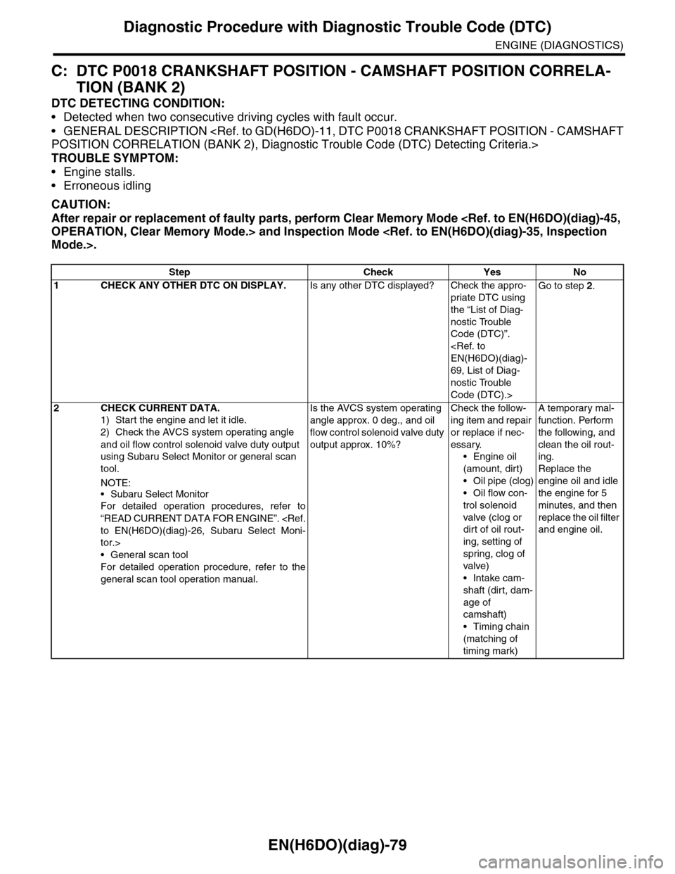
C: DTC P0018 CRANKSHAFT POSITION - CAMSHAFT POSITION CORRELA-
TION (BANK 2)
DTC DETECTING CONDITION:
•Detected when two consecutive driving cycles with fault occur.
•GENERAL DESCRIPTION
POSITION CORRELATION (BANK 2), Diagnostic Trouble Code (DTC) Detecting Criteria.>
TROUBLE SYMPTOM:
•Engine stalls.
•Erroneous idling
CAUTION:
After repair or replacement of faulty parts, perform Clear Memory Mode
OPERATION, Clear Memory Mode.> and Inspection Mode
Mode.>.
Step Check Yes No
1CHECK ANY OTHER DTC ON DISPLAY.Is any other DTC displayed? Check the appro-
priate DTC using
the “List of Diag-
nostic Trouble
Code (DTC)”.
EN(H6DO)(diag)-
69, List of Diag-
nostic Trouble
Code (DTC).>
Go to step 2.
2CHECK CURRENT DATA.
1) Start the engine and let it idle.
2) Check the AVCS system operating angle
and oil flow control solenoid valve duty output
using Subaru Select Monitor or general scan
tool.
NOTE:
•Subaru Select Monitor
For detailed operation procedures, refer to
“READ CURRENT DATA FOR ENGINE”.
to EN(H6DO)(diag)-26, Subaru Select Moni-
tor.>
•General scan tool
For detailed operation procedure, refer to the
general scan tool operation manual.
Is the AVCS system operating
angle approx. 0 deg., and oil
flow control solenoid valve duty
output approx. 10%?
Check the follow-
ing item and repair
or replace if nec-
essary.
•Engine oil
(amount, dirt)
•Oil pipe (clog)
•Oil flow con-
trol solenoid
valve (clog or
dirt of oil rout-
ing, setting of
spring, clog of
valve)
•Intake cam-
shaft (dirt, dam-
age of
camshaft)
•Timing chain
(matching of
timing mark)
A temporary mal-
function. Perform
the following, and
clean the oil rout-
ing.
Replace the
engine oil and idle
the engine for 5
minutes, and then
replace the oil filter
and engine oil.
Page 1241 of 2453
EN(H6DO)(diag)-80
Diagnostic Procedure with Diagnostic Trouble Code (DTC)
ENGINE (DIAGNOSTICS)
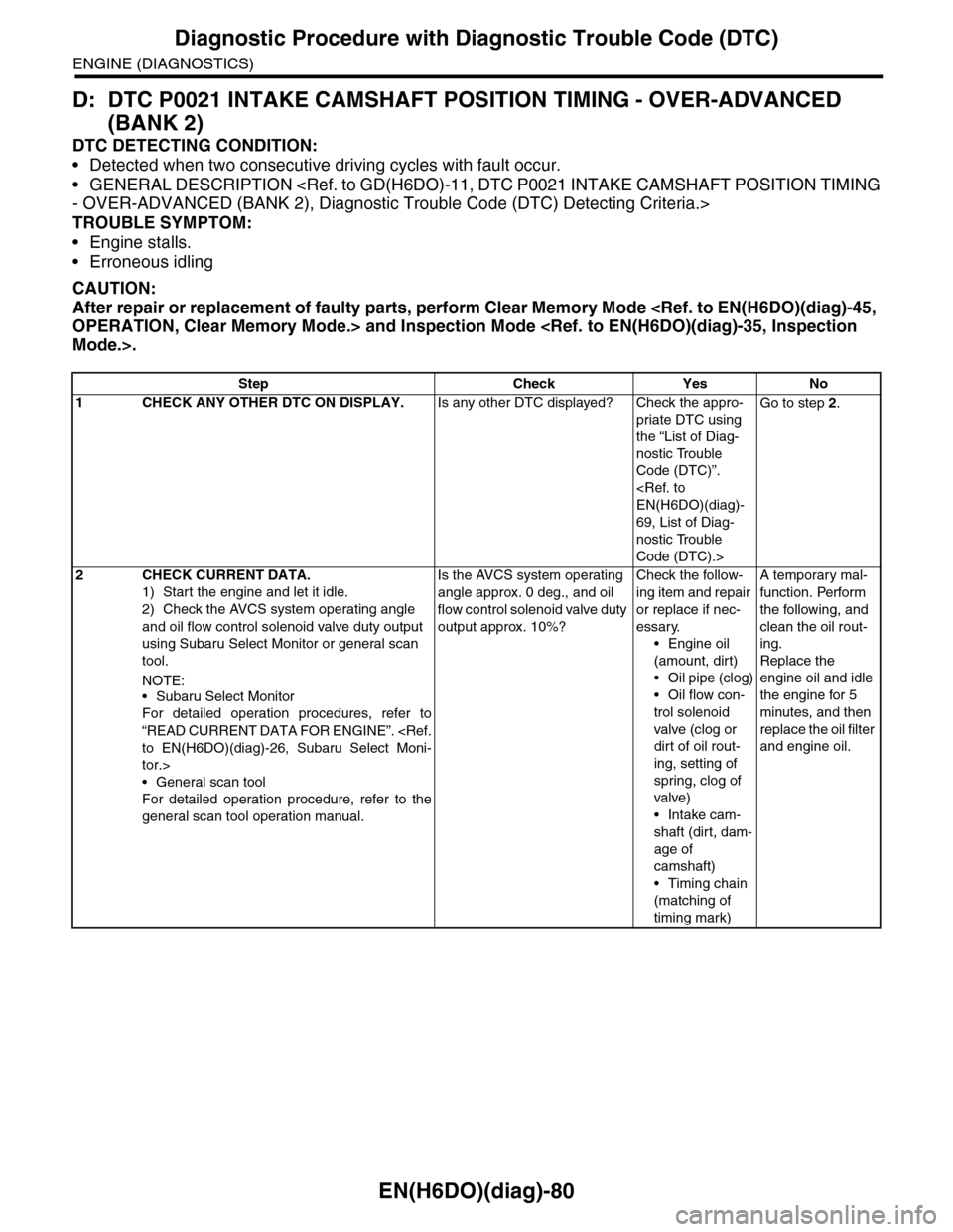
D: DTC P0021 INTAKE CAMSHAFT POSITION TIMING - OVER-ADVANCED
(BANK 2)
DTC DETECTING CONDITION:
•Detected when two consecutive driving cycles with fault occur.
•GENERAL DESCRIPTION
- OVER-ADVANCED (BANK 2), Diagnostic Trouble Code (DTC) Detecting Criteria.>
TROUBLE SYMPTOM:
•Engine stalls.
•Erroneous idling
CAUTION:
After repair or replacement of faulty parts, perform Clear Memory Mode
OPERATION, Clear Memory Mode.> and Inspection Mode
Mode.>.
Step Check Yes No
1CHECK ANY OTHER DTC ON DISPLAY.Is any other DTC displayed? Check the appro-
priate DTC using
the “List of Diag-
nostic Trouble
Code (DTC)”.
EN(H6DO)(diag)-
69, List of Diag-
nostic Trouble
Code (DTC).>
Go to step 2.
2CHECK CURRENT DATA.
1) Start the engine and let it idle.
2) Check the AVCS system operating angle
and oil flow control solenoid valve duty output
using Subaru Select Monitor or general scan
tool.
NOTE:
•Subaru Select Monitor
For detailed operation procedures, refer to
“READ CURRENT DATA FOR ENGINE”.
to EN(H6DO)(diag)-26, Subaru Select Moni-
tor.>
•General scan tool
For detailed operation procedure, refer to the
general scan tool operation manual.
Is the AVCS system operating
angle approx. 0 deg., and oil
flow control solenoid valve duty
output approx. 10%?
Check the follow-
ing item and repair
or replace if nec-
essary.
•Engine oil
(amount, dirt)
•Oil pipe (clog)
•Oil flow con-
trol solenoid
valve (clog or
dirt of oil rout-
ing, setting of
spring, clog of
valve)
•Intake cam-
shaft (dirt, dam-
age of
camshaft)
•Timing chain
(matching of
timing mark)
A temporary mal-
function. Perform
the following, and
clean the oil rout-
ing.
Replace the
engine oil and idle
the engine for 5
minutes, and then
replace the oil filter
and engine oil.
Page 1242 of 2453
EN(H6DO)(diag)-81
Diagnostic Procedure with Diagnostic Trouble Code (DTC)
ENGINE (DIAGNOSTICS)
E: DTC P0026 INTAKE VALVE CONTROL SOLENOID CIRCUIT RANGE/PER-
FORMANCE (BANK 1)
DTC DETECTING CONDITION:
•Immediately at fault recognition
•GENERAL DESCRIPTION
CIRCUIT RANGE/PERFORMANCE (BANK 1), Diagnostic Trouble Code (DTC) Detecting Criteria.>
TROUBLE SYMPTOM:
Erroneous idling
CAUTION:
After repair or replacement of faulty parts, perform Clear Memory Mode
OPERATION, Clear Memory Mode.> and Inspection Mode
Inspection Mode.>.
WIRING DIAGRAM:
EN-03655
B134
31
B20
E19
ECM
B20
1234567891011 121314 15 16
1
VARIABLE VALVE LIFT DIAGNOSIS OIL PRESSURE SWITCH RH
E71
B134
85610 11 12 13 14 157213416
3019 20 2228 29
91718252123 24323126 2733 34
Page 1243 of 2453
EN(H6DO)(diag)-82
Diagnostic Procedure with Diagnostic Trouble Code (DTC)
ENGINE (DIAGNOSTICS)
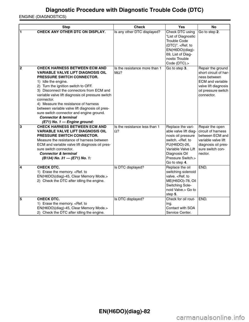
Step Check Yes No
1CHECK ANY OTHER DTC ON DISPLAY.Is any other DTC displayed? Check DTC using
“List of Diagnostic
Tr o u b l e C o d e
(DTC)”.
EN(H6DO)(diag)-
69, List of Diag-
nostic Trouble
Code (DTC).>
Go to step 2.
2CHECK HARNESS BETWEEN ECM AND
VARIABLE VALVE LIFT DIAGNOSIS OIL
PRESSURE SWITCH CONNECTOR.
1) Idle the engine.
2) Turn the ignition switch to OFF.
3) Disconnect the connectors from ECM and
variable valve lift diagnosis oil pressure switch
connector.
4) Measure the resistance of harness
between variable valve lift diagnosis oil pres-
sure switch connector and engine ground.
Connector & terminal
(E71) No. 1 — Engine ground:
Is the resistance more than 1
MΩ?
Go to step 3.Repair the ground
short circuit of har-
ness between
ECM and variable
valve lift diagnosis
oil pressure switch
connector.
3CHECK HARNESS BETWEEN ECM AND
VARIABLE VALVE LIFT DIAGNOSIS OIL
PRESSURE SWITCH CONNECTOR.
Measure the resistance of harness between
ECM and variable valve lift diagnosis oil pres-
sure switch connector.
Connector & terminal
(B134) No. 31 — (E71) No. 1:
Is the resistance less than 1
Ω?
Replace the vari-
able valve lift diag-
nosis oil pressure
switch.
FU(H6DO)-26,
Va r i a bl e Va l ve L i f t
Diagnosis Oil
Pressure Switch.>
Go to step 4.
Repair the open
circuit of harness
between ECM and
variable valve lift
diagnosis oil pres-
sure switch con-
nector.
4CHECK DTC.
1) Erase the memory.
EN(H6DO)(diag)-45, Clear Memory Mode.>
2) Check the DTC after idling the engine.
Is DTC displayed? Replace the oil
switching solenoid
valve.
ME(H6DO)-78, Oil
Switching Sole-
noid Valve.> Go to
step 5.
END.
5CHECK DTC.
1) Erase the memory.
EN(H6DO)(diag)-45, Clear Memory Mode.>
2) Check the DTC after idling the engine.
Is DTC displayed? Check for oil rout-
ing.
Contact with SOA
Service Center.
END.
Page 1244 of 2453
EN(H6DO)(diag)-83
Diagnostic Procedure with Diagnostic Trouble Code (DTC)
ENGINE (DIAGNOSTICS)
F: DTC P0028 INTAKE VALVE CONTROL SOLENOID CIRCUIT RANGE/PER-
FORMANCE (BANK 2)
DTC DETECTING CONDITION:
•Immediately at fault recognition
•GENERAL DESCRIPTION
CIRCUIT RANGE/PERFORMANCE (BANK 2), Diagnostic Trouble Code (DTC) Detecting Criteria.>
TROUBLE SYMPTOM:
Erroneous idling
CAUTION:
After repair or replacement of faulty parts, perform Clear Memory Mode
OPERATION, Clear Memory Mode.> and Inspection Mode
Inspection Mode.>.
WIRING DIAGRAM:
EN-03656
B134
32
B20
E110
ECM
B20
1234567891011 121314 15 16
VARIABLE VALVE LIFT DIAGNOSISOIL PRESSURE SWITCH LH
E72
B134
85610 11 12 13 14 157213416
3019 20 2228 29
91718252123 24323126 2733 34
Page 1245 of 2453
EN(H6DO)(diag)-84
Diagnostic Procedure with Diagnostic Trouble Code (DTC)
ENGINE (DIAGNOSTICS)
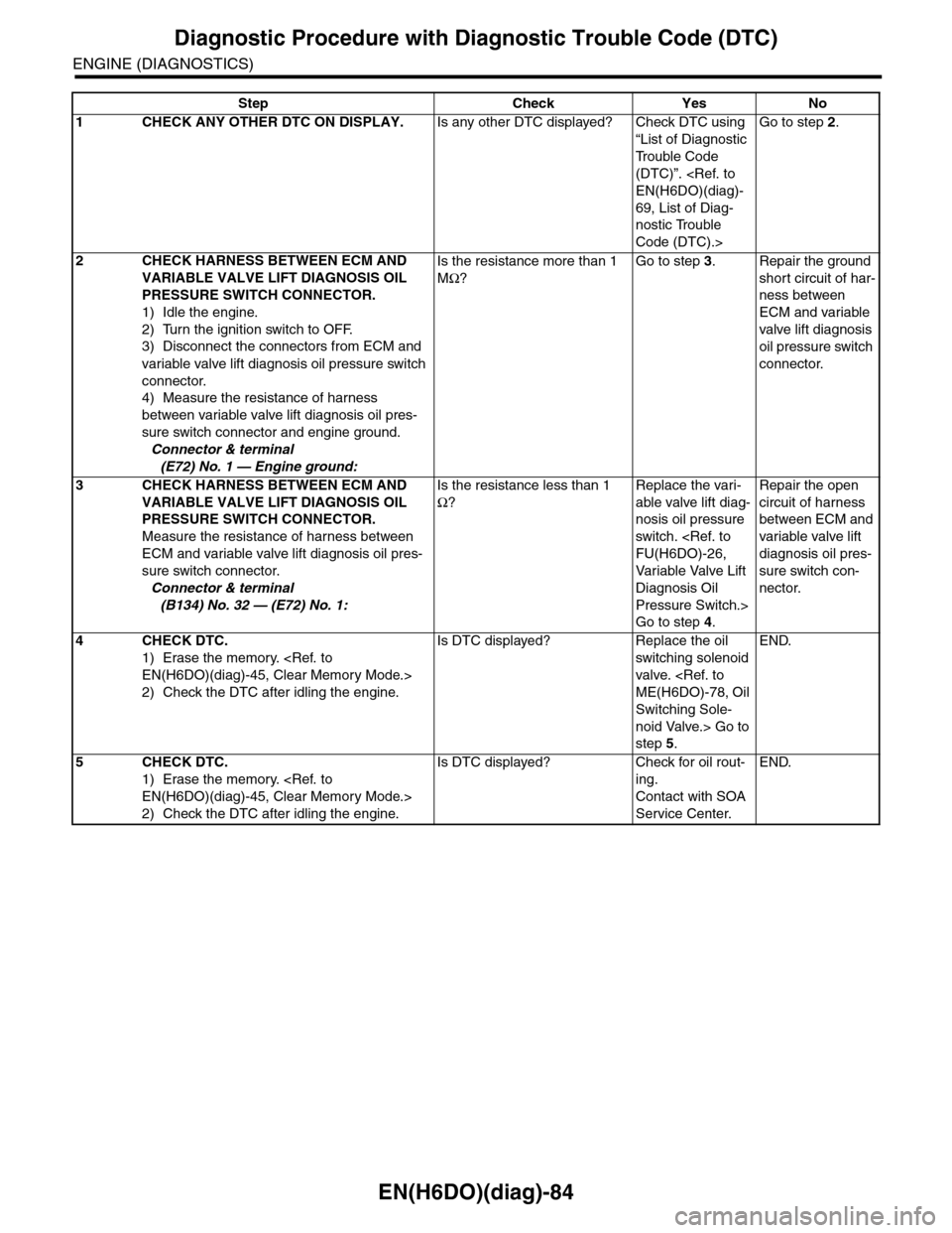
Step Check Yes No
1CHECK ANY OTHER DTC ON DISPLAY.Is any other DTC displayed? Check DTC using
“List of Diagnostic
Tr o u b l e C o d e
(DTC)”.
EN(H6DO)(diag)-
69, List of Diag-
nostic Trouble
Code (DTC).>
Go to step 2.
2CHECK HARNESS BETWEEN ECM AND
VARIABLE VALVE LIFT DIAGNOSIS OIL
PRESSURE SWITCH CONNECTOR.
1) Idle the engine.
2) Turn the ignition switch to OFF.
3) Disconnect the connectors from ECM and
variable valve lift diagnosis oil pressure switch
connector.
4) Measure the resistance of harness
between variable valve lift diagnosis oil pres-
sure switch connector and engine ground.
Connector & terminal
(E72) No. 1 — Engine ground:
Is the resistance more than 1
MΩ?
Go to step 3.Repair the ground
short circuit of har-
ness between
ECM and variable
valve lift diagnosis
oil pressure switch
connector.
3CHECK HARNESS BETWEEN ECM AND
VARIABLE VALVE LIFT DIAGNOSIS OIL
PRESSURE SWITCH CONNECTOR.
Measure the resistance of harness between
ECM and variable valve lift diagnosis oil pres-
sure switch connector.
Connector & terminal
(B134) No. 32 — (E72) No. 1:
Is the resistance less than 1
Ω?
Replace the vari-
able valve lift diag-
nosis oil pressure
switch.
FU(H6DO)-26,
Va r i a bl e Va l ve L i f t
Diagnosis Oil
Pressure Switch.>
Go to step 4.
Repair the open
circuit of harness
between ECM and
variable valve lift
diagnosis oil pres-
sure switch con-
nector.
4CHECK DTC.
1) Erase the memory.
EN(H6DO)(diag)-45, Clear Memory Mode.>
2) Check the DTC after idling the engine.
Is DTC displayed? Replace the oil
switching solenoid
valve.
ME(H6DO)-78, Oil
Switching Sole-
noid Valve.> Go to
step 5.
END.
5CHECK DTC.
1) Erase the memory.
EN(H6DO)(diag)-45, Clear Memory Mode.>
2) Check the DTC after idling the engine.
Is DTC displayed? Check for oil rout-
ing.
Contact with SOA
Service Center.
END.
Page 1282 of 2453
EN(H6DO)(diag)-121
Diagnostic Procedure with Diagnostic Trouble Code (DTC)
ENGINE (DIAGNOSTICS)
R: DTC P0076 INTAKE VALVE CONTROL CIRCUIT LOW (BANK 1)
DTC DETECTING CONDITION:
•Immediately at fault recognition
•GENERAL DESCRIPTION
LOW (BANK 1), Diagnostic Trouble Code (DTC) Detecting Criteria.>
TROUBLE SYMPTOM:
Erroneous idling
CAUTION:
After repair or replacement of faulty parts, perform Clear Memory Mode
OPERATION, Clear Memory Mode.> and Inspection Mode
Inspection Mode.>.
WIRING DIAGRAM:
EN-03658
B21
E2
B137
E69
24
21
2625
E69
12
25
ECM
OIL SWITCHING SOLENOID VALVE RH
B21
123412131415567816171819910 1120212223 24 25 2627 28 29 3031 32 33
3534 37363938 41404342 4445 47464948 51505352 54
B137
85610 11 12 13 14 157213416
3019 20 2228 29
91718 2521 23 243126 27
Page 1283 of 2453
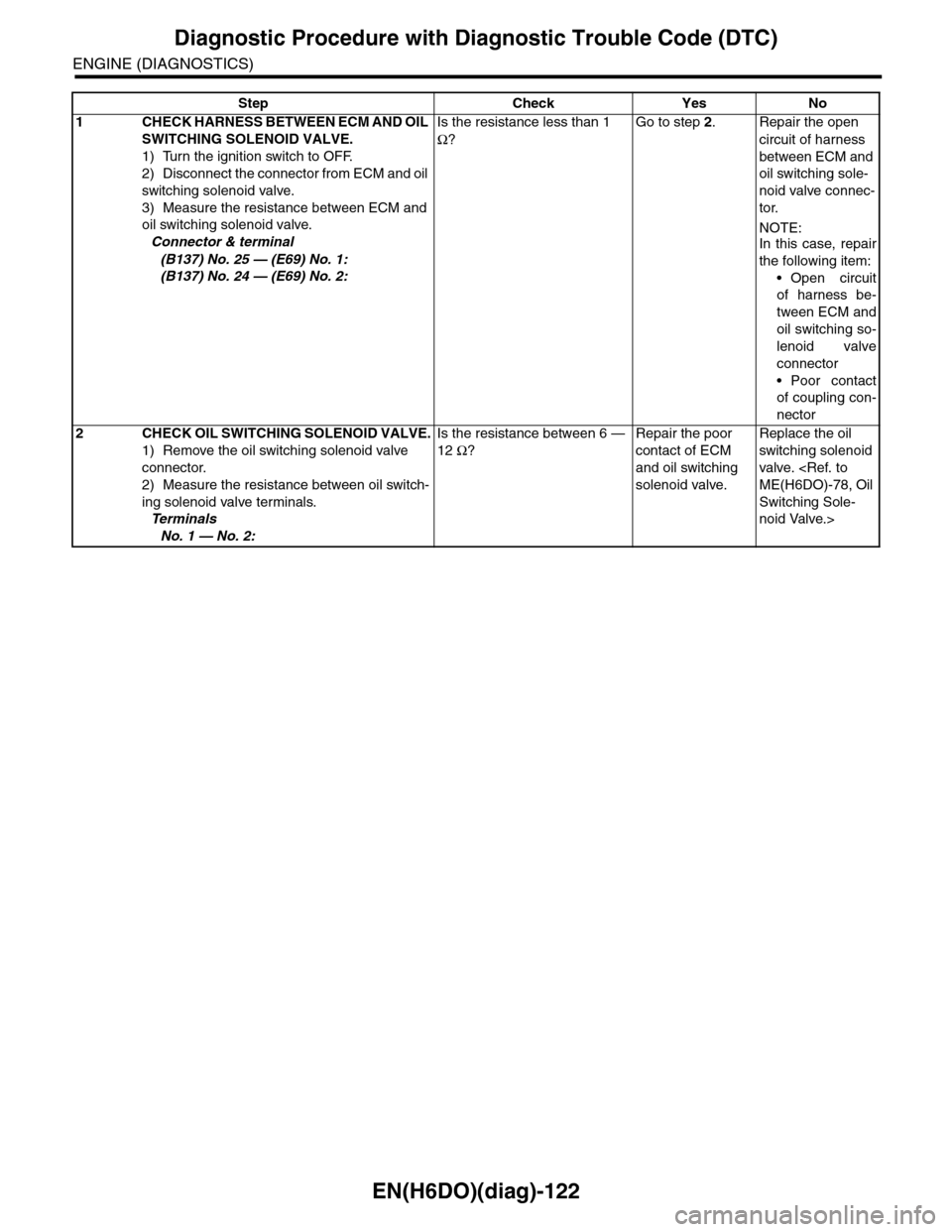
EN(H6DO)(diag)-122
Diagnostic Procedure with Diagnostic Trouble Code (DTC)
ENGINE (DIAGNOSTICS)
Step Check Yes No
1CHECK HARNESS BETWEEN ECM AND OIL
SWITCHING SOLENOID VALVE.
1) Turn the ignition switch to OFF.
2) Disconnect the connector from ECM and oil
switching solenoid valve.
3) Measure the resistance between ECM and
oil switching solenoid valve.
Connector & terminal
(B137) No. 25 — (E69) No. 1:
(B137) No. 24 — (E69) No. 2:
Is the resistance less than 1
Ω?
Go to step 2.Repair the open
circuit of harness
between ECM and
oil switching sole-
noid valve connec-
tor.
NOTE:In this case, repair
the following item:
•Open circuit
of harness be-
tween ECM and
oil switching so-
lenoid valve
connector
•Poor contact
of coupling con-
nector
2CHECK OIL SWITCHING SOLENOID VALVE.
1) Remove the oil switching solenoid valve
connector.
2) Measure the resistance between oil switch-
ing solenoid valve terminals.
Te r m i n a l s
No. 1 — No. 2:
Is the resistance between 6 —
12 Ω?
Repair the poor
contact of ECM
and oil switching
solenoid valve.
Replace the oil
switching solenoid
valve.
ME(H6DO)-78, Oil
Switching Sole-
noid Valve.>