2009 SUBARU TRIBECA engine oil
[x] Cancel search: engine oilPage 1553 of 2453
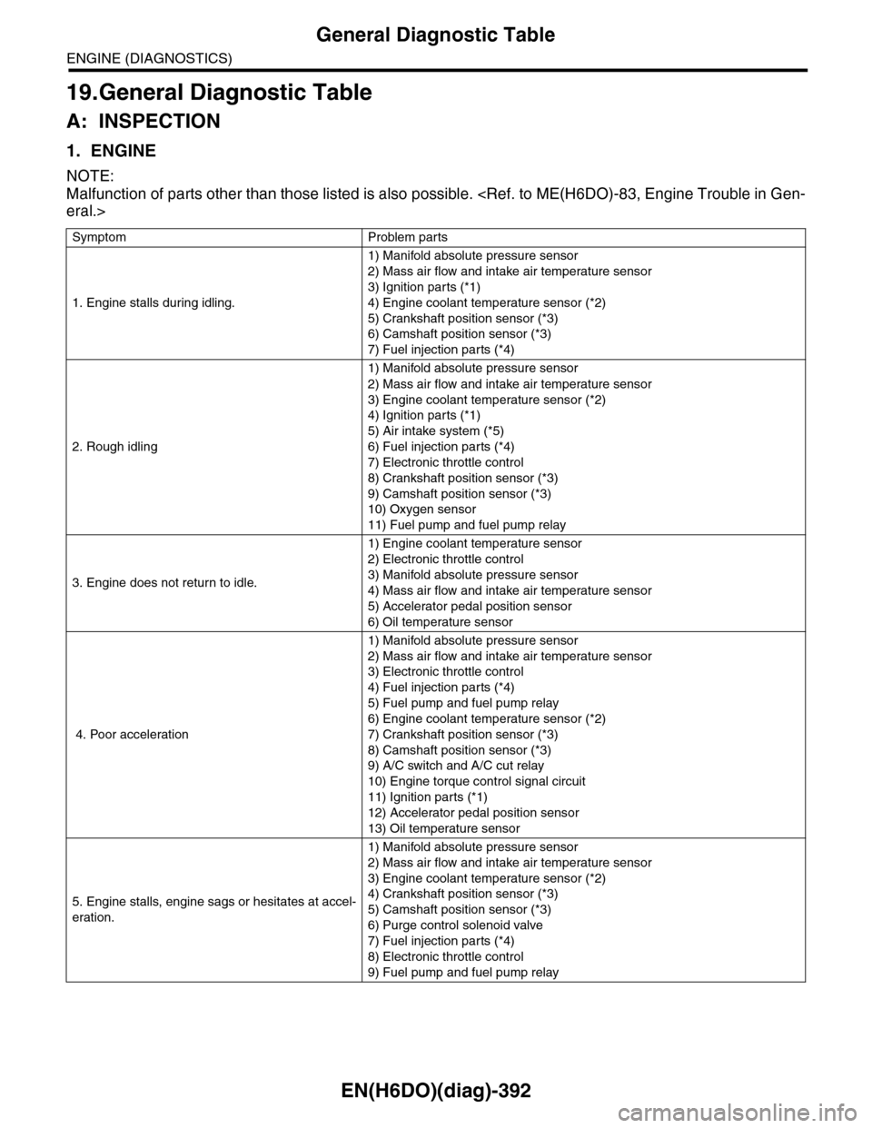
EN(H6DO)(diag)-392
General Diagnostic Table
ENGINE (DIAGNOSTICS)
19.General Diagnostic Table
A: INSPECTION
1. ENGINE
NOTE:
Malfunction of parts other than those listed is also possible.
Symptom Problem parts
1. Engine stalls during idling.
1) Manifold absolute pressure sensor
2) Mass air flow and intake air temperature sensor
3) Ignition parts (*1)
4) Engine coolant temperature sensor (*2)
5) Crankshaft position sensor (*3)
6) Camshaft position sensor (*3)
7) Fuel injection parts (*4)
2. Rough idling
1) Manifold absolute pressure sensor
2) Mass air flow and intake air temperature sensor
3) Engine coolant temperature sensor (*2)
4) Ignition parts (*1)
5) Air intake system (*5)
6) Fuel injection parts (*4)
7) Electronic throttle control
8) Crankshaft position sensor (*3)
9) Camshaft position sensor (*3)
10) Oxygen sensor
11) Fuel pump and fuel pump relay
3. Engine does not return to idle.
1) Engine coolant temperature sensor
2) Electronic throttle control
3) Manifold absolute pressure sensor
4) Mass air flow and intake air temperature sensor
5) Accelerator pedal position sensor
6) Oil temperature sensor
4. Poor acceleration
1) Manifold absolute pressure sensor
2) Mass air flow and intake air temperature sensor
3) Electronic throttle control
4) Fuel injection parts (*4)
5) Fuel pump and fuel pump relay
6) Engine coolant temperature sensor (*2)
7) Crankshaft position sensor (*3)
8) Camshaft position sensor (*3)
9) A/C switch and A/C cut relay
10) Engine torque control signal circuit
11) Ignition parts (*1)
12) Accelerator pedal position sensor
13) Oil temperature sensor
5. Engine stalls, engine sags or hesitates at accel-
eration.
1) Manifold absolute pressure sensor
2) Mass air flow and intake air temperature sensor
3) Engine coolant temperature sensor (*2)
4) Crankshaft position sensor (*3)
5) Camshaft position sensor (*3)
6) Purge control solenoid valve
7) Fuel injection parts (*4)
8) Electronic throttle control
9) Fuel pump and fuel pump relay
Page 1554 of 2453
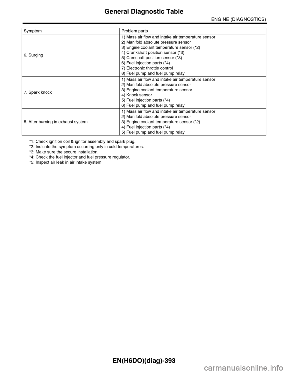
EN(H6DO)(diag)-393
General Diagnostic Table
ENGINE (DIAGNOSTICS)
*1: Check ignition coil & ignitor assembly and spark plug.
*2: Indicate the symptom occurring only in cold temperatures.
*3: Make sure the secure installation.
*4: Check the fuel injector and fuel pressure regulator.
*5: Inspect air leak in air intake system.
6. Surging
1) Mass air flow and intake air temperature sensor
2) Manifold absolute pressure sensor
3) Engine coolant temperature sensor (*2)
4) Crankshaft position sensor (*3)
5) Camshaft position sensor (*3)
6) Fuel injection parts (*4)
7) Electronic throttle control
8) Fuel pump and fuel pump relay
7. Spark knock
1) Mass air flow and intake air temperature sensor
2) Manifold absolute pressure sensor
3) Engine coolant temperature sensor
4) Knock sensor
5) Fuel injection parts (*4)
6) Fuel pump and fuel pump relay
8. After burning in exhaust system
1) Mass air flow and intake air temperature sensor
2) Manifold absolute pressure sensor
3) Engine coolant temperature sensor (*2)
4) Fuel injection parts (*4)
5) Fuel pump and fuel pump relay
Symptom Problem parts
Page 1616 of 2453
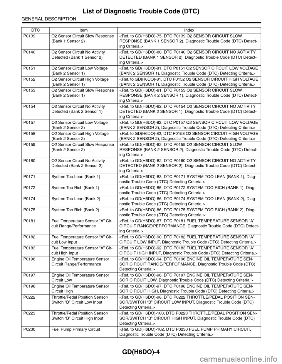
GD(H6DO)-4
List of Diagnostic Trouble Code (DTC)
GENERAL DESCRIPTION
P0139 O2 Sensor Circuit Slow Response
(Bank 1 Sensor 2)
ing Criteria.>
P0140 O2 Sensor Circuit No Activity
Detected (Bank 1 Sensor 2)
ing Criteria.>
P0151 O2 Sensor Circuit Low Voltage
(Bank 2 Sensor 1)
P0152 O2 Sensor Circuit High Voltage
(Bank 2 Sensor 1)
P0153 O2 Sensor Circuit Slow Response
(Bank 2 Sensor 1)
ing Criteria.>
P0154 O2 Sensor Circuit No Activity
Detected (Bank 2 Sensor 1)
ing Criteria.>
P0157 O2 Sensor Circuit Low Voltage
(Bank 2 Sensor 2)
P0158 O2 Sensor Circuit High Voltage
(Bank 2 Sensor 2)
P0159 O2 Sensor Circuit Slow Response
(Bank 2 Sensor 2)
ing Criteria.>
P0160 O2 Sensor Circuit No Activity
Detected (Bank 2 Sensor 2)
ing Criteria.>
P0171 System Too Lean (Bank 1)
P0172 System Too Rich (Bank 1)
P0174 System Too Lean (Bank 2)
P0175 System Too Rich (Bank 2)
P0181 Fuel Temperature Sensor “A” Cir-
cuit Range/Performance
ing Criteria.>
P0182 Fuel Temperature Sensor “A” Cir-
cuit Low Input
P0183 Fuel Temperature Sensor “A” Cir-
cuit High Input
P0196 Engine Oil Temperature Sensor
Circuit Range/Performance
Detecting Criteria.>
P0197 Engine Oil Temperature Sensor
Circuit Low
P0198 Engine Oil Temperature Sensor
Circuit High
P0222 Throttle/Pedal Position Sensor/
Switch “B” Circuit Low Input
Detecting Criteria.>
P0223 Throttle/Pedal Position Sensor/
Switch “B” Circuit High Input
Detecting Criteria.>
P0230 Fuel Pump Primary Circuit
DTC Item Index
Page 1621 of 2453
GD(H6DO)-9
Diagnostic Trouble Code (DTC) Detecting Criteria
GENERAL DESCRIPTION
2. Diagnostic Trouble Code (DTC) Detecting Criteria
A: DTC P0011 INTAKE CAMSHAFT POSITION TIMING - OVER-ADVANCED
(BANK 1)
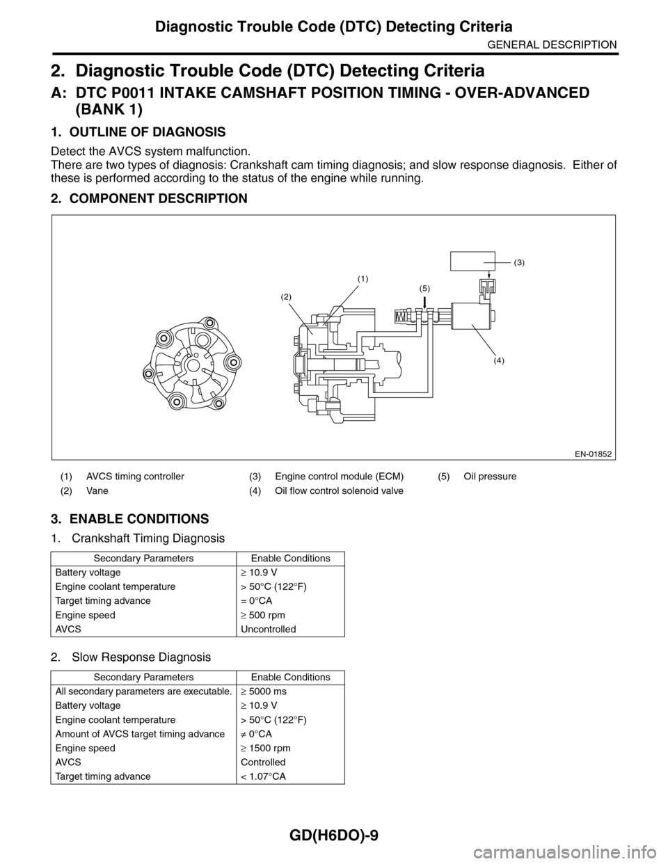
1. OUTLINE OF DIAGNOSIS
Detect the AVCS system malfunction.
There are two types of diagnosis: Crankshaft cam timing diagnosis; and slow response diagnosis. Either of
these is performed according to the status of the engine while running.
2. COMPONENT DESCRIPTION
3. ENABLE CONDITIONS
1. Crankshaft Timing Diagnosis
2. Slow Response Diagnosis
(1) AVCS timing controller (3) Engine control module (ECM) (5) Oil pressure
(2) Vane (4) Oil flow control solenoid valve
Secondary Parameters Enable Conditions
Battery voltage≥ 10.9 V
Engine coolant temperature > 50°C (122°F)
Ta r g e t t i m i n g a d v a n c e = 0 ° C A
Engine speed≥ 500 rpm
AV C S U n c o n t r o l l e d
Secondary Parameters Enable Conditions
All secondary parameters are executable.≥ 5000 ms
Battery voltage≥ 10.9 V
Engine coolant temperature > 50°C (122°F)
Amount of AVCS target timing advance≠ 0°CA
Engine speed≥ 1500 rpm
AV C S C o n t r o l l e d
Ta r g e t t i m i n g a d v a n c e < 1 . 0 7 ° C A
EN-01852
(3)
(4)
(1)(5)(2)
Page 1625 of 2453
GD(H6DO)-13
Diagnostic Trouble Code (DTC) Detecting Criteria
GENERAL DESCRIPTION
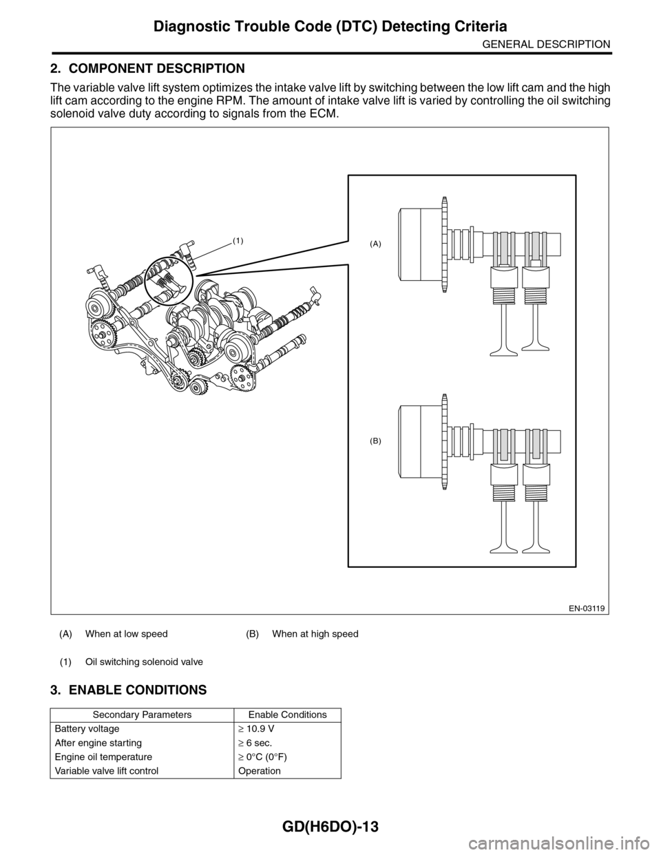
2. COMPONENT DESCRIPTION
The variable valve lift system optimizes the intake valve lift by switching between the low lift cam and the high
lift cam according to the engine RPM. The amount of intake valve lift is varied by controlling the oil switching
solenoid valve duty according to signals from the ECM.
3. ENABLE CONDITIONS
(A) When at low speed (B) When at high speed
(1) Oil switching solenoid valve
Secondary Parameters Enable Conditions
Battery voltage≥ 10.9 V
After engine starting≥ 6 sec.
Engine oil temperature≥ 0°C (0°F)
Va r i a b l e va l v e l i f t c o n t r o l O p e r a t i o n
EN-03119
(1)
(B)
(A)
Page 1706 of 2453
GD(H6DO)-94
Diagnostic Trouble Code (DTC) Detecting Criteria
GENERAL DESCRIPTION
BH:DTC P0196 ENGINE OIL TEMPERATURE SENSOR CIRCUIT RANGE/PER-
FORMANCE
1. OUTLINE OF DIAGNOSIS
Detect for abnormal values in the oil temperature sensor output properties.
Judge as NG when the oil temperature does not rise even though the engine is running under a condition
where it should rise.
2. ENABLE CONDITIONS
3. GENERAL DRIVING CYCLE
Perform the diagnosis continuously after starting the engine.
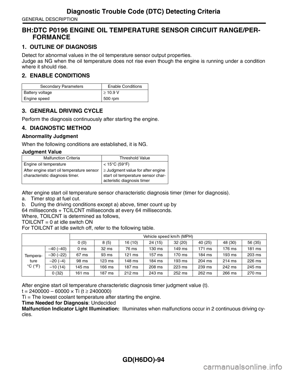
4. DIAGNOSTIC METHOD
Abnormality Judgment
When the following conditions are established, it is NG.
After engine start oil temperature sensor characteristic diagnosis timer (timer for diagnosis).
a. Timer stop at fuel cut.
b. During the driving conditions except a) above, timer count up by
64 milliseconds + TCILCNT milliseconds at every 64 milliseconds.
Where, TOILCNT is determined as follows,
TOILCNT = 0 at idle switch ON
For TOILCNT at Idle switch off, refer to the following table.
After engine start oil temperature characteristic diagnosis timer judgment value (t).
t = 2400000 – 60000 × Ti (t ≥ 2400000)
Ti = The lowest coolant temperature after starting the engine.
Time Needed for Diagnosis: Undecided
Malfunction Indicator Light Illumination: Illuminates when malfunctions occur in 2 continuous driving cy-
cles.
Secondary Parameters Enable Conditions
Battery voltage≥ 10.9 V
Engine speed 500 rpm
Judgment Value
Malfunction Criteria Threshold Value
Engine oil temperature < 15°C (59°F)
After engine start oil temperature sensor
characteristic diagnosis timer.
≥ Judgment value for after engine
start oil temperature sensor char-
acteristic diagnosis timer
Vehicle speed km/h (MPH)
0 (0) 8 (5) 16 (10) 24 (15) 32 (20) 40 (25) 48 (30) 56 (35)
Te m p e r a -
ture
°C (°F)
–40 (–40) 0 ms 32 ms 76 ms 130 ms 149 ms 171 ms 176 ms 181 ms
–30 (–22) 67 ms 93 ms 121 ms 157 ms 170 ms 184 ms 193 ms 203 ms
–20 (–4) 98 ms 123 ms 148 ms 184 ms 193 ms 204 ms 214 ms 226 ms
–10 (14) 145 ms 166 ms 187 ms 208 ms 223 ms 239 ms 242 ms 245 ms
0 (32) 161 ms 187 ms 212 ms 243 ms 252 ms 262 ms 266 ms 270 ms
Page 1707 of 2453
GD(H6DO)-95
Diagnostic Trouble Code (DTC) Detecting Criteria
GENERAL DESCRIPTION
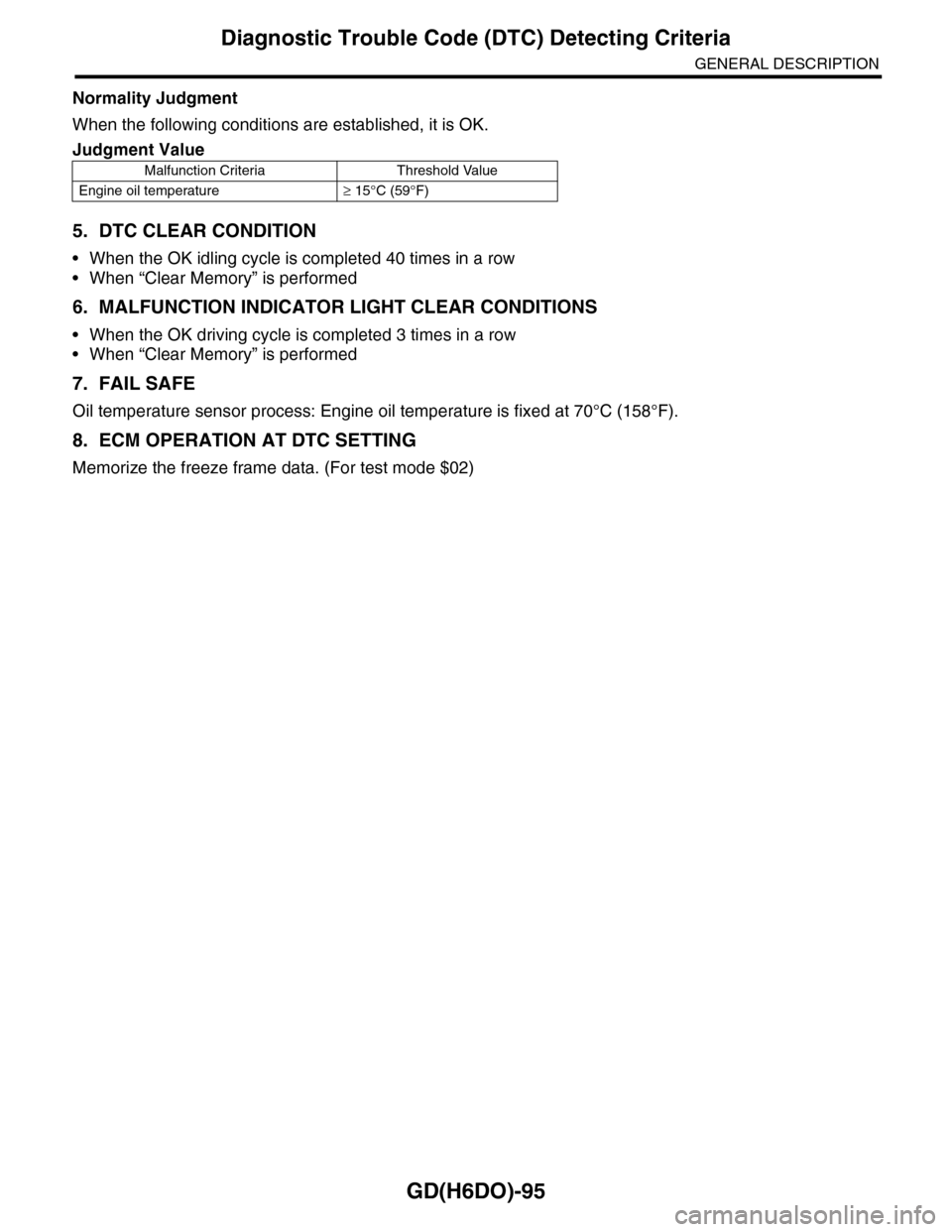
Normality Judgment
When the following conditions are established, it is OK.
5. DTC CLEAR CONDITION
•When the OK idling cycle is completed 40 times in a row
•When “Clear Memory” is performed
6. MALFUNCTION INDICATOR LIGHT CLEAR CONDITIONS
•When the OK driving cycle is completed 3 times in a row
•When “Clear Memory” is performed
7. FAIL SAFE
Oil temperature sensor process: Engine oil temperature is fixed at 70°C (158°F).
8. ECM OPERATION AT DTC SETTING
Memorize the freeze frame data. (For test mode $02)
Judgment Value
Malfunction Criteria Threshold Value
Engine oil temperature≥ 15°C (59°F)
Page 1708 of 2453
GD(H6DO)-96
Diagnostic Trouble Code (DTC) Detecting Criteria
GENERAL DESCRIPTION
BI: DTC P0197 ENGINE OIL TEMPERATURE SENSOR CIRCUIT LOW
1. OUTLINE OF DIAGNOSIS
Detect the open or short circuit of the oil temperature sensor.
Judge as NG when outside of the possible range.
2. ENABLE CONDITIONS
3. GENERAL DRIVING CYCLE
Always perform the diagnosis continuously.
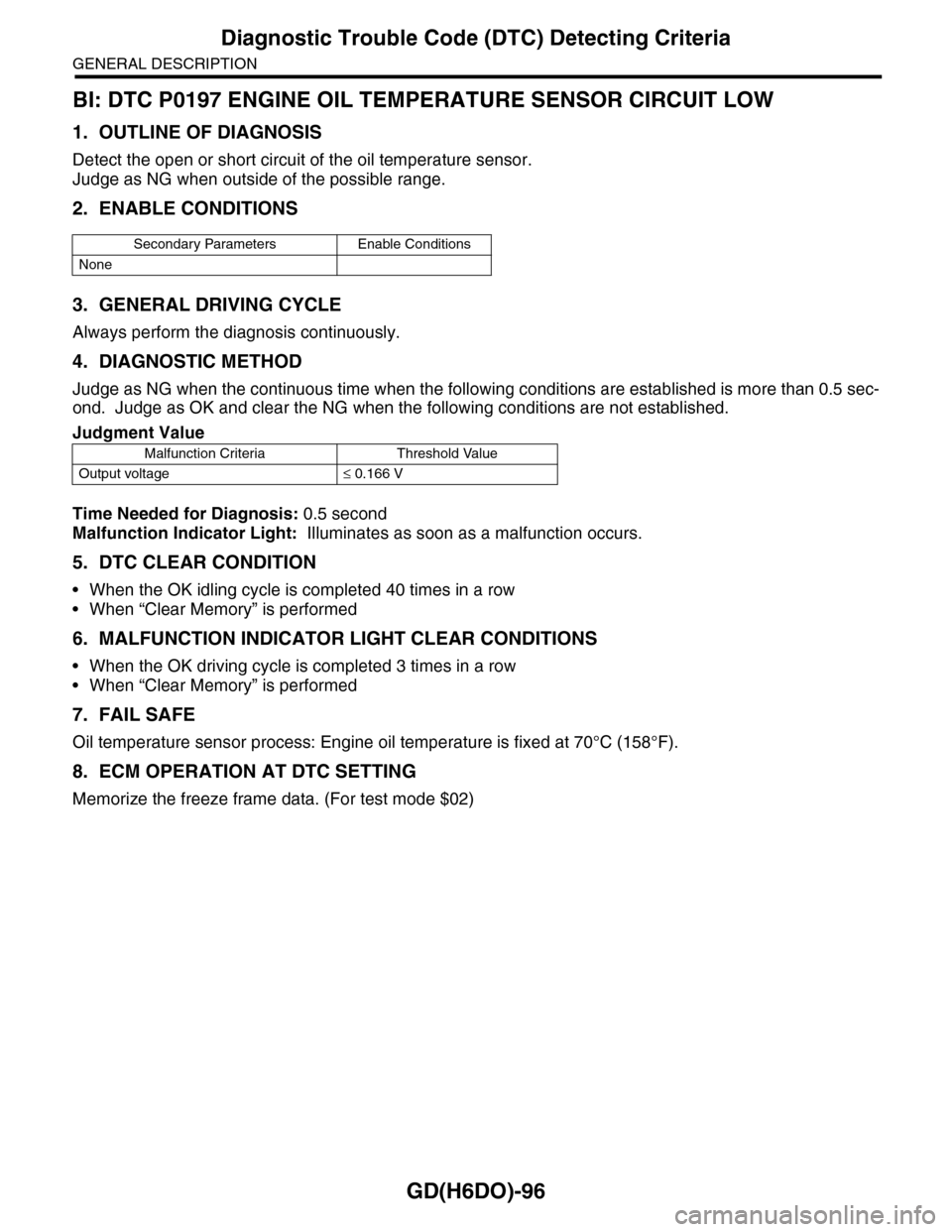
4. DIAGNOSTIC METHOD
Judge as NG when the continuous time when the following conditions are established is more than 0.5 sec-
ond. Judge as OK and clear the NG when the following conditions are not established.
Time Needed for Diagnosis: 0.5 second
Malfunction Indicator Light: Illuminates as soon as a malfunction occurs.
5. DTC CLEAR CONDITION
•When the OK idling cycle is completed 40 times in a row
•When “Clear Memory” is performed
6. MALFUNCTION INDICATOR LIGHT CLEAR CONDITIONS
•When the OK driving cycle is completed 3 times in a row
•When “Clear Memory” is performed
7. FAIL SAFE
Oil temperature sensor process: Engine oil temperature is fixed at 70°C (158°F).
8. ECM OPERATION AT DTC SETTING
Memorize the freeze frame data. (For test mode $02)
Secondary Parameters Enable Conditions
None
Judgment Value
Malfunction Criteria Threshold Value
Output voltage≤ 0.166 V