Page 1390 of 2453
EN(H6DO)(diag)-229
Diagnostic Procedure with Diagnostic Trouble Code (DTC)
ENGINE (DIAGNOSTICS)
BI: DTC P0197 ENGINE OIL TEMPERATURE SENSOR CIRCUIT LOW
DTC DETECTING CONDITION:
•Immediately at fault recognition
•GENERAL DESCRIPTION
CIRCUIT LOW, Diagnostic Trouble Code (DTC) Detecting Criteria.>
TROUBLE SYMPTOM:
•Hard to start
•Erroneous idling
•Poor driving performance
CAUTION:
After repair or replacement of faulty parts, perform Clear Memory Mode
OPERATION, Clear Memory Mode.> and Inspection Mode
Inspection Mode.>.
WIRING DIAGRAM:
EN-03662
E75
E2
B21
B134 ECM
1
19
29
E1
B20
2
3
23
E75
12
B20
1234567891011 121314 15 16
B21
123412131415567816171819910 1120212223 24 25 2627 28 29 3031 32 33
3534 37363938 41404342 4445 47464948 51505352 54
OILTEMPERATURESENSOR
B134
85610 11 12 13 14 157213416
3019 20 2228 29
91718252123 24323126 2733 34
Page 1391 of 2453
EN(H6DO)(diag)-230
Diagnostic Procedure with Diagnostic Trouble Code (DTC)
ENGINE (DIAGNOSTICS)
Step Check Yes No
1CHECK HARNESS BETWEEN OIL TEMPER-
ATURE SENSOR AND ECM CONNECTOR.
1) Disconnect the ECM connector and oil tem-
perature sensor connector.
2) Measure the resistance of harness
between oil temperature sensor connector and
engine ground.
Connector & terminal
(B134) No. 23 — Engine ground:
(B134) No. 29 — Engine ground:
Is the resistance more than 1
MΩ?
Go to step 2.Repair the ground
short circuit
between ECM and
oil temperature
sensor connector.
2CHECK POOR CONTACT.
Check poor contact of oil temperature sensor
connector.
Is there poor contact in oil tem-
perature sensor connector?
Repair the poor
contact.
Replace the oil
temperature sen-
sor.
FU(H6DO)-27, Oil
Te m p e r a t u r e S e n -
sor.>
Page 1392 of 2453
EN(H6DO)(diag)-231
Diagnostic Procedure with Diagnostic Trouble Code (DTC)
ENGINE (DIAGNOSTICS)
BJ:DTC P0198 ENGINE OIL TEMPERATURE SENSOR CIRCUIT HIGH
DTC DETECTING CONDITION:
•Immediately at fault recognition
•GENERAL DESCRIPTION
CIRCUIT HIGH, Diagnostic Trouble Code (DTC) Detecting Criteria.>
TROUBLE SYMPTOM:
•Hard to start
•Erroneous idling
•Poor driving performance
CAUTION:
After repair or replacement of faulty parts, perform Clear Memory Mode
OPERATION, Clear Memory Mode.> and Inspection Mode
Inspection Mode.>.
WIRING DIAGRAM:
EN-03662
E75
E2
B21
B134 ECM
1
19
29
E1
B20
2
3
23
E75
12
B20
1234567891011 121314 15 16
B21
123412131415567816171819910 1120212223 24 25 2627 28 29 3031 32 33
3534 37363938 41404342 4445 47464948 51505352 54
OILTEMPERATURESENSOR
B134
85610 11 12 13 14 157213416
3019 20 2228 29
91718252123 24323126 2733 34
Page 1393 of 2453

EN(H6DO)(diag)-232
Diagnostic Procedure with Diagnostic Trouble Code (DTC)
ENGINE (DIAGNOSTICS)
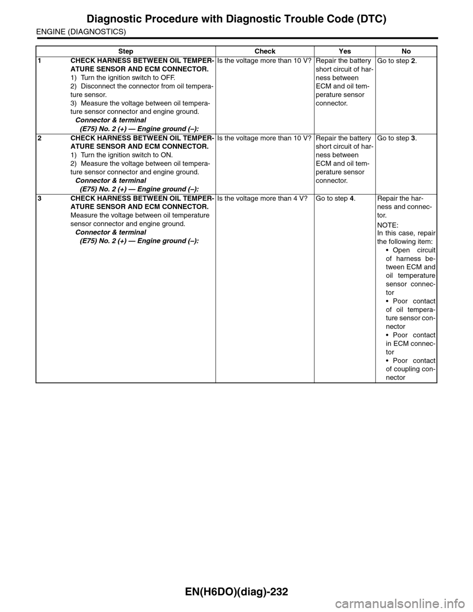
Step Check Yes No
1CHECK HARNESS BETWEEN OIL TEMPER-
ATURE SENSOR AND ECM CONNECTOR.
1) Turn the ignition switch to OFF.
2) Disconnect the connector from oil tempera-
ture sensor.
3) Measure the voltage between oil tempera-
ture sensor connector and engine ground.
Connector & terminal
(E75) No. 2 (+) — Engine ground (–):
Is the voltage more than 10 V? Repair the battery
short circuit of har-
ness between
ECM and oil tem-
perature sensor
connector.
Go to step 2.
2CHECK HARNESS BETWEEN OIL TEMPER-
ATURE SENSOR AND ECM CONNECTOR.
1) Turn the ignition switch to ON.
2) Measure the voltage between oil tempera-
ture sensor connector and engine ground.
Connector & terminal
(E75) No. 2 (+) — Engine ground (–):
Is the voltage more than 10 V? Repair the battery
short circuit of har-
ness between
ECM and oil tem-
perature sensor
connector.
Go to step 3.
3CHECK HARNESS BETWEEN OIL TEMPER-
ATURE SENSOR AND ECM CONNECTOR.
Measure the voltage between oil temperature
sensor connector and engine ground.
Connector & terminal
(E75) No. 2 (+) — Engine ground (–):
Is the voltage more than 4 V? Go to step 4.Repair the har-
ness and connec-
tor.
NOTE:
In this case, repair
the following item:
•Open circuit
of harness be-
tween ECM and
oil temperature
sensor connec-
tor
•Poor contact
of oil tempera-
ture sensor con-
nector
•Poor contact
in ECM connec-
tor
•Poor contact
of coupling con-
nector
Page 1394 of 2453
EN(H6DO)(diag)-233
Diagnostic Procedure with Diagnostic Trouble Code (DTC)
ENGINE (DIAGNOSTICS)
4CHECK HARNESS BETWEEN OIL TEMPER-
ATURE SENSOR AND ECM CONNECTOR.
1) Turn the ignition switch to OFF.
2) Measure the resistance of harness
between oil temperature sensor connector and
engine ground.
Connector & terminal
(E75) No. 1 — Engine ground:
Is the resistance less than 5
Ω?
Replace the oil
temperature sen-
sor.
FU(H6DO)-27, Oil
Te m p e r a t u r e S e n -
sor.>
Repair the har-
ness and connec-
tor.
NOTE:In this case, repair
the following item:
•Open circuit
of harness be-
tween ECM and
oil temperature
sensor connec-
tor
•Poor contact
of oil tempera-
ture sensor con-
nector
•Poor contact
in ECM connec-
tor
•Poor contact
of coupling con-
nector
•Poor contact
of joint connec-
tor
Step Check Yes No
Page 1408 of 2453

EN(H6DO)(diag)-247
Diagnostic Procedure with Diagnostic Trouble Code (DTC)
ENGINE (DIAGNOSTICS)
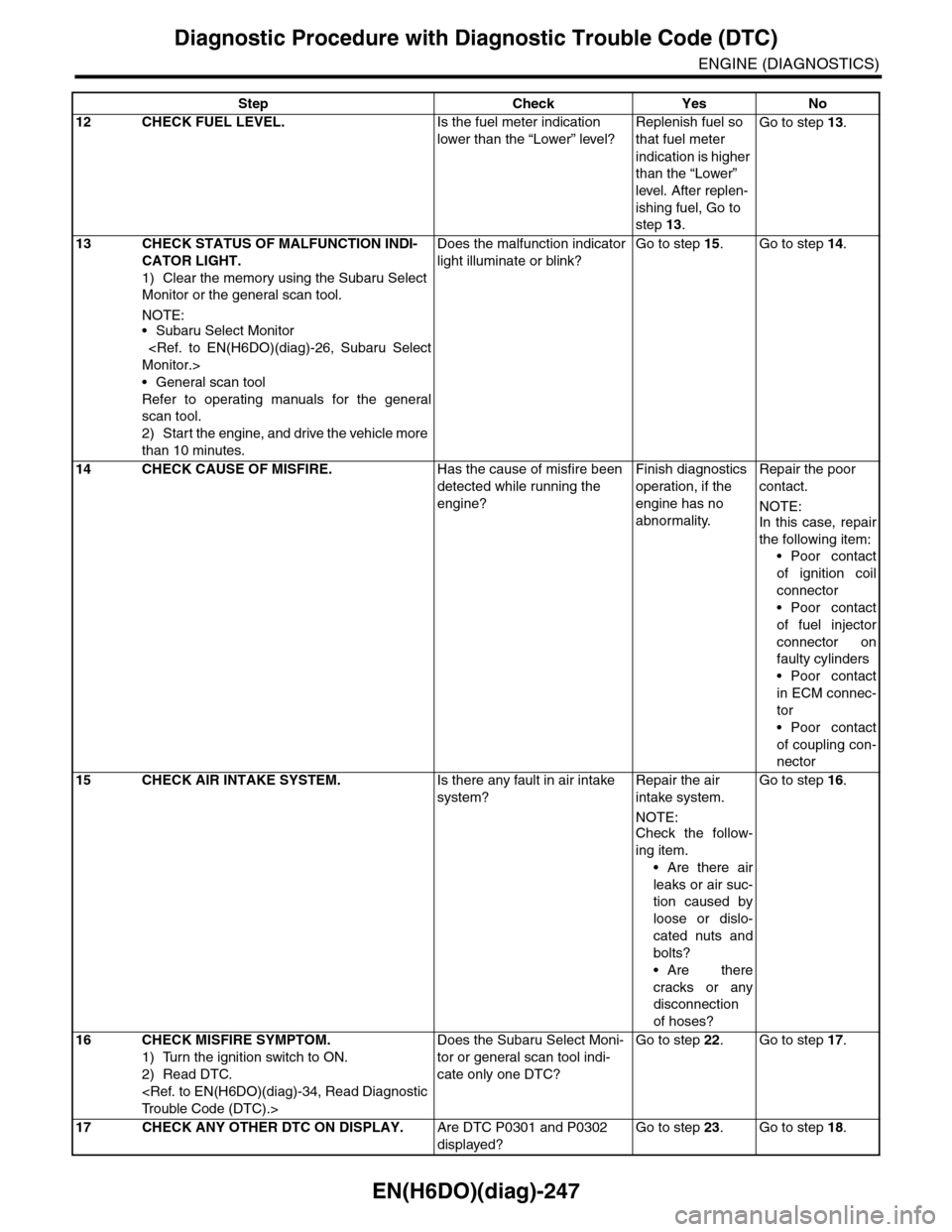
12 CHECK FUEL LEVEL.Is the fuel meter indication
lower than the “Lower” level?
Replenish fuel so
that fuel meter
indication is higher
than the “Lower”
level. After replen-
ishing fuel, Go to
step 13.
Go to step 13.
13 CHECK STATUS OF MALFUNCTION INDI-
CATOR LIGHT.
1) Clear the memory using the Subaru Select
Monitor or the general scan tool.
NOTE:•Subaru Select Monitor
Monitor.>
•General scan tool
Refer to operating manuals for the general
scan tool.
2) Start the engine, and drive the vehicle more
than 10 minutes.
Does the malfunction indicator
light illuminate or blink?
Go to step 15.Go to step 14.
14 CHECK CAUSE OF MISFIRE.Has the cause of misfire been
detected while running the
engine?
Finish diagnostics
operation, if the
engine has no
abnormality.
Repair the poor
contact.
NOTE:In this case, repair
the following item:
•Poor contact
of ignition coil
connector
•Poor contact
of fuel injector
connector on
faulty cylinders
•Poor contact
in ECM connec-
tor
•Poor contact
of coupling con-
nector
15 CHECK AIR INTAKE SYSTEM.Is there any fault in air intake
system?
Repair the air
intake system.
NOTE:
Check the follow-
ing item.
•Are there air
leaks or air suc-
tion caused by
loose or dislo-
cated nuts and
bolts?
•Are there
cracks or any
disconnection
of hoses?
Go to step 16.
16 CHECK MISFIRE SYMPTOM.
1) Turn the ignition switch to ON.
2) Read DTC.
Tr o u b l e C o d e ( D T C ) . >
Does the Subaru Select Moni-
tor or general scan tool indi-
cate only one DTC?
Go to step 22.Go to step 17.
17 CHECK ANY OTHER DTC ON DISPLAY.Are DTC P0301 and P0302
displayed?
Go to step 23.Go to step 18.
Step Check Yes No
Page 1409 of 2453

EN(H6DO)(diag)-248
Diagnostic Procedure with Diagnostic Trouble Code (DTC)
ENGINE (DIAGNOSTICS)
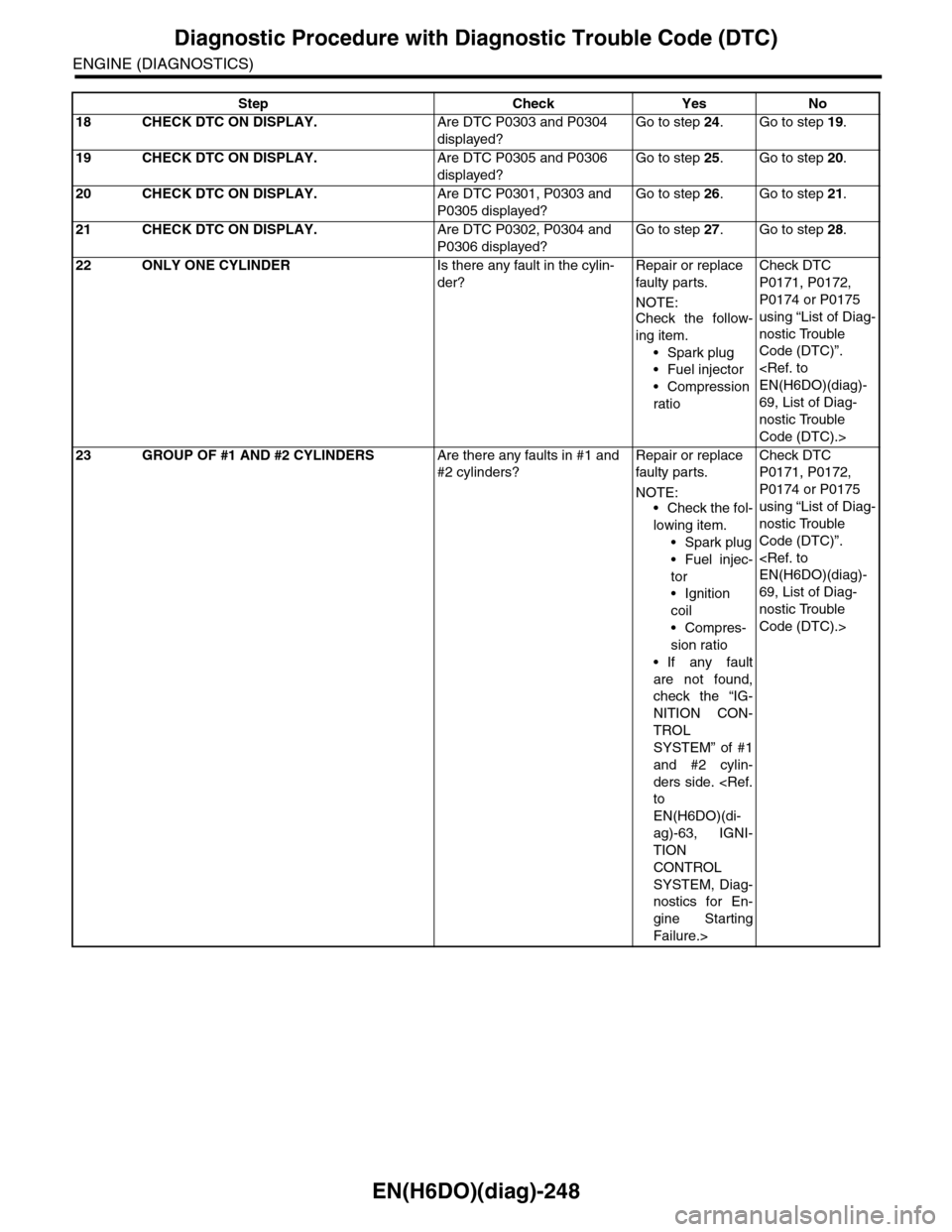
18 CHECK DTC ON DISPLAY.Are DTC P0303 and P0304
displayed?
Go to step 24.Go to step 19.
19 CHECK DTC ON DISPLAY.Are DTC P0305 and P0306
displayed?
Go to step 25.Go to step 20.
20 CHECK DTC ON DISPLAY.Are DTC P0301, P0303 and
P0305 displayed?
Go to step 26.Go to step 21.
21 CHECK DTC ON DISPLAY.Are DTC P0302, P0304 and
P0306 displayed?
Go to step 27.Go to step 28.
22 ONLY ONE CYLINDERIs there any fault in the cylin-
der?
Repair or replace
faulty par ts.
NOTE:Check the follow-
ing item.
•Spark plug
•Fuel injector
•Compression
ratio
Check DTC
P0171, P0172,
P0174 or P0175
using “List of Diag-
nostic Trouble
Code (DTC)”.
EN(H6DO)(diag)-
69, List of Diag-
nostic Trouble
Code (DTC).>
23 GROUP OF #1 AND #2 CYLINDERSAre there any faults in #1 and
#2 cylinders?
Repair or replace
faulty par ts.
NOTE:•Check the fol-
lowing item.
•Spark plug
•Fuel injec-
tor
•Ignition
coil
•Compres-
sion ratio
•If any fault
are not found,
check the “IG-
NITION CON-
TROL
SYSTEM” of #1
and #2 cylin-
ders side.
to
EN(H6DO)(di-
ag)-63, IGNI-
TION
CONTROL
SYSTEM, Diag-
nostics for En-
gine Starting
Failure.>
Check DTC
P0171, P0172,
P0174 or P0175
using “List of Diag-
nostic Trouble
Code (DTC)”.
EN(H6DO)(diag)-
69, List of Diag-
nostic Trouble
Code (DTC).>
Step Check Yes No
Page 1410 of 2453

EN(H6DO)(diag)-249
Diagnostic Procedure with Diagnostic Trouble Code (DTC)
ENGINE (DIAGNOSTICS)
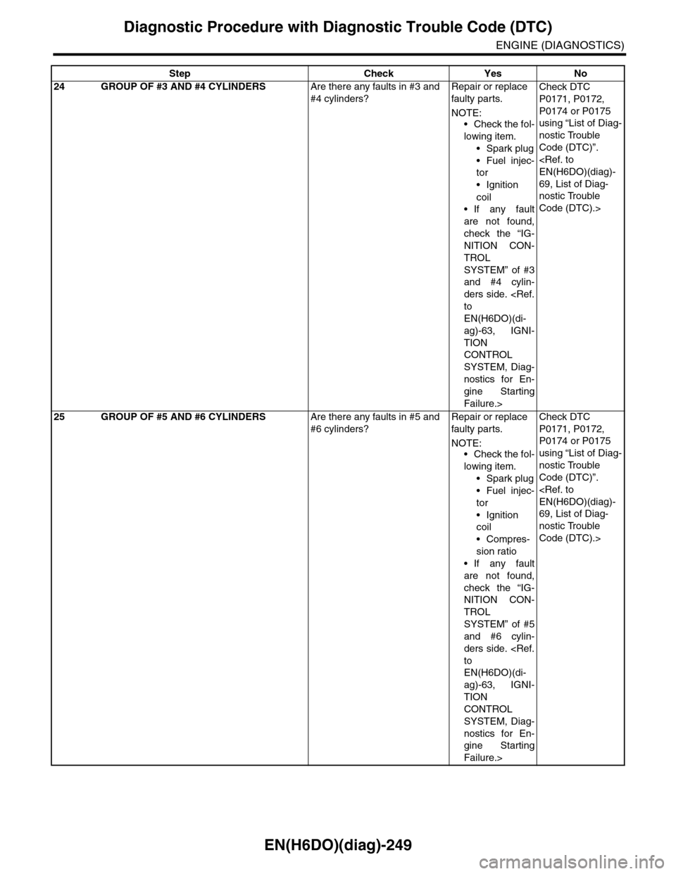
24 GROUP OF #3 AND #4 CYLINDERSAre there any faults in #3 and
#4 cylinders?
Repair or replace
faulty par ts.
NOTE:
•Check the fol-
lowing item.
•Spark plug
•Fuel injec-
tor
•Ignition
coil
•If any fault
are not found,
check the “IG-
NITION CON-
TROL
SYSTEM” of #3
and #4 cylin-
ders side.
to
EN(H6DO)(di-
ag)-63, IGNI-
TION
CONTROL
SYSTEM, Diag-
nostics for En-
gine Starting
Failure.>
Check DTC
P0171, P0172,
P0174 or P0175
using “List of Diag-
nostic Trouble
Code (DTC)”.
EN(H6DO)(diag)-
69, List of Diag-
nostic Trouble
Code (DTC).>
25 GROUP OF #5 AND #6 CYLINDERSAre there any faults in #5 and
#6 cylinders?
Repair or replace
faulty par ts.
NOTE:•Check the fol-
lowing item.
•Spark plug
•Fuel injec-
tor
•Ignition
coil
•Compres-
sion ratio
•If any fault
are not found,
check the “IG-
NITION CON-
TROL
SYSTEM” of #5
and #6 cylin-
ders side.
to
EN(H6DO)(di-
ag)-63, IGNI-
TION
CONTROL
SYSTEM, Diag-
nostics for En-
gine Starting
Failure.>
Check DTC
P0171, P0172,
P0174 or P0175
using “List of Diag-
nostic Trouble
Code (DTC)”.
EN(H6DO)(diag)-
69, List of Diag-
nostic Trouble
Code (DTC).>
Step Check Yes No