2009 SUBARU TRIBECA brake fluid
[x] Cancel search: brake fluidPage 2047 of 2453
5AT-31
Time Lag Test
AUTOMATIC TRANSMISSION
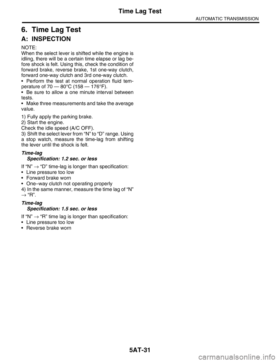
6. Time Lag Test
A: INSPECTION
NOTE:
When the select lever is shifted while the engine is
idling, there will be a certain time elapse or lag be-
fore shock is felt. Using this, check the condition of
forward brake, reverse brake, 1st one-way clutch,
forward one-way clutch and 3rd one-way clutch.
•Perform the test at normal operation fluid tem-
perature of 70 — 80°C (158 — 176°F).
•Be sure to allow a one minute interval between
tests.
•Make three measurements and take the average
value.
1) Fully apply the parking brake.
2) Start the engine.
Check the idle speed (A/C OFF).
3) Shift the select lever from “N” to “D” range. Using
a stop watch, measure the time-lag from shifting
the lever until the shock is felt.
Time-lag
Specification: 1.2 sec. or less
If “N” → “D” time-lag is longer than specification:
•Line pressure too low
•Forward brake worn
•One–way clutch not operating properly
4) In the same manner, measure the time lag of “N”
→ “R”.
Time-lag
Specification: 1.5 sec. or less
If “N” → “R” time lag is longer than specification:
•Line pressure too low
•Reverse brake worn
Page 2145 of 2453
5AT(diag)-28
List of Diagnostic Trouble Code (DTC)
AUTOMATIC TRANSMISSION (DIAGNOSTICS)
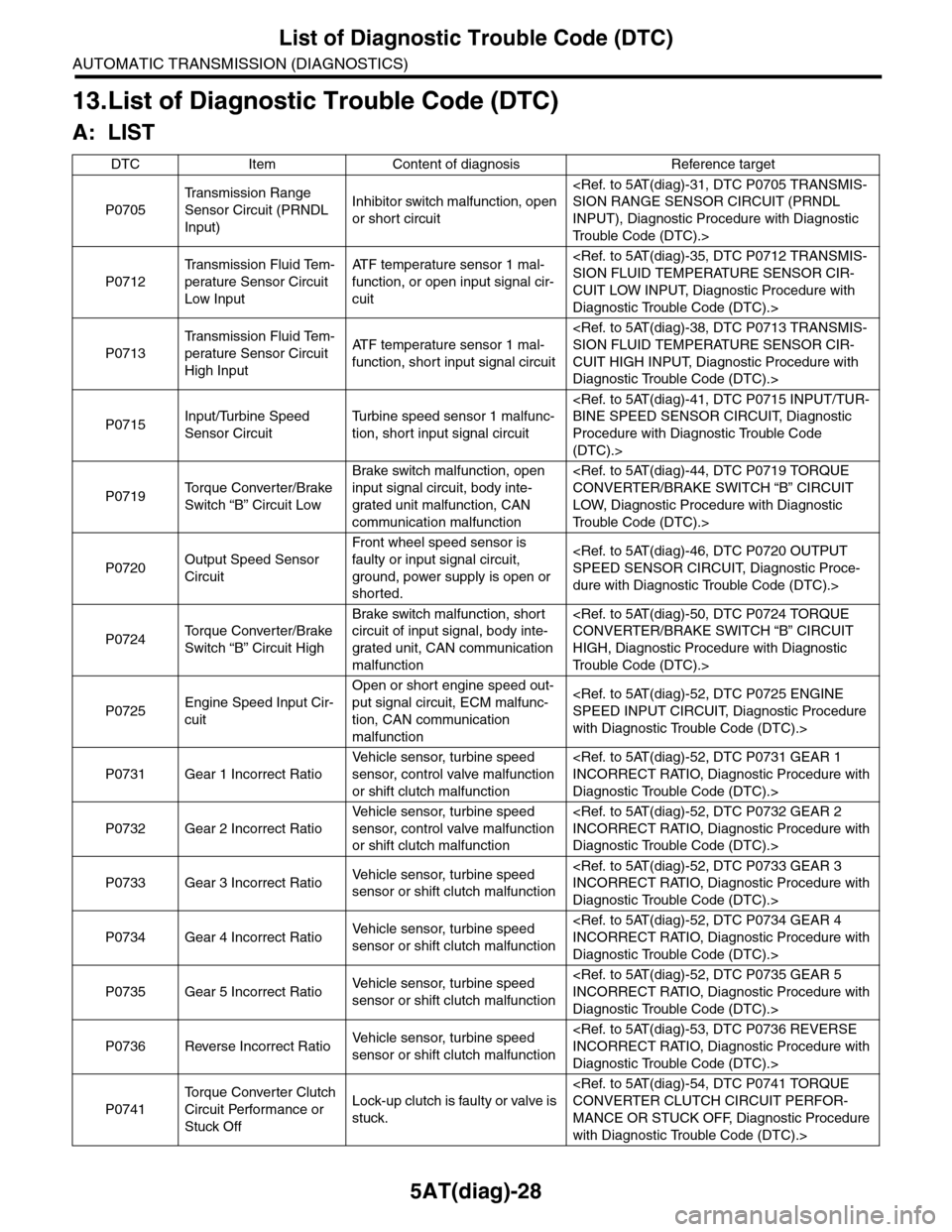
13.List of Diagnostic Trouble Code (DTC)
A: LIST
DTC Item Content of diagnosis Reference target
P0705
Tr a n s m i s s i o n R a n g e
Sensor Circuit (PRNDL
Input)
Inhibitor switch malfunction, open
or short circuit
INPUT), Diagnostic Procedure with Diagnostic
Tr o u b l e C o d e ( D T C ) . >
P0712
Tr a n s m i s s i o n F l u i d Te m -
perature Sensor Circuit
Low Input
AT F t e m p e r a t u r e s e n s o r 1 m a l -
function, or open input signal cir-
cuit
CUIT LOW INPUT, Diagnostic Procedure with
Diagnostic Trouble Code (DTC).>
P0713
Tr a n s m i s s i o n F l u i d Te m -
perature Sensor Circuit
High Input
AT F t e m p e r a t u r e s e n s o r 1 m a l -
function, short input signal circuit
CUIT HIGH INPUT, Diagnostic Procedure with
Diagnostic Trouble Code (DTC).>
P0715Input/Turbine Speed
Sensor Circuit
Tu r b i n e s p e e d s e n s o r 1 m a l f u n c -
tion, short input signal circuit
Procedure with Diagnostic Trouble Code
(DTC).>
P0719To r q u e C o n v e r t e r / B r a k e
Switch “B” Circuit Low
Brake switch malfunction, open
input signal circuit, body inte-
grated unit malfunction, CAN
communication malfunction
LOW, Diagnostic Procedure with Diagnostic
Tr o u b l e C o d e ( D T C ) . >
P0720Output Speed Sensor
Circuit
Front wheel speed sensor is
faulty or input signal circuit,
ground, power supply is open or
shorted.
dure with Diagnostic Trouble Code (DTC).>
P0724To r q u e C o n v e r t e r / B r a k e
Switch “B” Circuit High
Brake switch malfunction, short
circuit of input signal, body inte-
grated unit, CAN communication
malfunction
HIGH, Diagnostic Procedure with Diagnostic
Tr o u b l e C o d e ( D T C ) . >
P0725Engine Speed Input Cir-
cuit
Open or short engine speed out-
put signal circuit, ECM malfunc-
tion, CAN communication
malfunction
with Diagnostic Trouble Code (DTC).>
P0731 Gear 1 Incorrect Ratio
Ve h i c l e s e n s o r, t u r b i n e s p e e d
sensor, control valve malfunction
or shift clutch malfunction
Diagnostic Trouble Code (DTC).>
P0732 Gear 2 Incorrect Ratio
Ve h i c l e s e n s o r, t u r b i n e s p e e d
sensor, control valve malfunction
or shift clutch malfunction
Diagnostic Trouble Code (DTC).>
P0733 Gear 3 Incorrect RatioVe h i c l e s e n s o r, t u r b i n e s p e e d
sensor or shift clutch malfunction
Diagnostic Trouble Code (DTC).>
P0734 Gear 4 Incorrect RatioVe h i c l e s e n s o r, t u r b i n e s p e e d
sensor or shift clutch malfunction
Diagnostic Trouble Code (DTC).>
P0735 Gear 5 Incorrect RatioVe h i c l e s e n s o r, t u r b i n e s p e e d
sensor or shift clutch malfunction
Diagnostic Trouble Code (DTC).>
P0736 Reverse Incorrect RatioVe h i c l e s e n s o r, t u r b i n e s p e e d
sensor or shift clutch malfunction
Diagnostic Trouble Code (DTC).>
P0741
To r q u e C o n v e r t e r C l u t c h
Circuit Performance or
Stuck Off
Lock-up clutch is faulty or valve is
stuck.
MANCE OR STUCK OFF, Diagnostic Procedure
with Diagnostic Trouble Code (DTC).>
Page 2147 of 2453
5AT(diag)-30
List of Diagnostic Trouble Code (DTC)
AUTOMATIC TRANSMISSION (DIAGNOSTICS)
P0957Backup Light Relay Cir-
cuit Low
Back-up relay output circuit is
open, shorted or relay OFF mal-
function
dure with Diagnostic Trouble Code (DTC).>
P0958Backup Light Relay Out-
put Circuit High
Back-up relay output circuit is
open, shorted or relay ON mal-
function
cedure with Diagnostic Trouble Code (DTC).>
P1601TCM Data Communica-
tion Failure
Communication Failure between
TCM and Memory Box
dure with Diagnostic Trouble Code (DTC).>
P1706
AT Ve h i c l e S p e e d S e n -
sor Circuit Malfunction
(Rear Wheel)
Rear wheel speed sensor is faulty
or input circuit, ground, power
supply is open or shorted.
TION (REAR WHEEL), Diagnostic Procedure
with Diagnostic Trouble Code (DTC).>
P1707AT A W D S o l e n o i d V a l v e
Circuit Malfunction
AWD solenoid circuit malfunction
or AWD solenoid body malfunc-
tion
Diagnostic Procedure with Diagnostic Trouble
Code (DTC).>
P1710
To r q u e C o n v e r t e r Tu r -
bine 2 Speed Signal Cir-
cuit 2 Malfunction
To r q u e c o n v e r t e r s e n s o r 2 m a l -
function, input circuit, ground,
power open, short circuit
CIRCUIT 2 MALFUNCTION, Diagnostic Proce-
dure with Diagnostic Trouble Code (DTC).>
P1716AT F Te m p . S e n s o r 2 C i r -
cuit Low
AT F t e m p e r a t u r e s e n s o r 2 m a l -
function, or open input signal cir-
cuit
dure with Diagnostic Trouble Code (DTC).>
P1717AT F Te m p . S e n s o r 2 C i r -
cuit High
AT F t e m p e r a t u r e s e n s o r 2 m a l -
function, short input signal circuit
dure with Diagnostic Trouble Code (DTC).>
P1718AT C A N C o m m u n i c a t i o n
Circuit
CAN communication line bus off
is open, EUM short circuit, ABS/
VDCCM, integrated CU malfunc-
tion
dure with Diagnostic Trouble Code (DTC).>
P1798 Gear 1 Engine Brake
Malfunction of clutch oil pressure
related to 1st engine brake, sole-
noid current malfunction
Diagnostic Trouble Code (DTC).>
P1799 Interlock
Malfunction of clutch oil pressure
which emit interlock, solenoid
current malfunction
Tr o u b l e C o d e ( D T C ) . >
P1817SPORT Mode Switch
Circuit (Manual Switch)
Manual mode switch is open or
shorted, or switch malfunction
Diagnostic Procedure with Diagnostic Trouble
Code (DTC).>
P1840
Tr a n s m i s s i o n F l u i d P r e s -
sure Sensor/Switch A
Circuit
Fr/B oil pressure switch is open or
shorted, or switch malfunction
CIRCUIT, Diagnostic Procedure with Diagnostic
Tr o u b l e C o d e ( D T C ) . >
P1842
Tr a n s m i s s i o n F l u i d P r e s -
sure Sensor/Switch C
Circuit
I/C oil pressure switch is open or
shorted, or switch malfunction.
CIRCUIT, Diagnostic Procedure with Diagnostic
Tr o u b l e C o d e ( D T C ) . >
P1843
Tr a n s m i s s i o n F l u i d P r e s -
sure Sensor/Switch D
Circuit
D/C oil pressure switch is open or
shorted, or switch malfunction.
CIRCUIT, Diagnostic Procedure with Diagnostic
Tr o u b l e C o d e ( D T C ) . >
P1844
Tr a n s m i s s i o n F l u i d P r e s -
sure Sensor/Switch E
Circuit
H&LR/C oil pressure switch is
open or shorted, or switch mal-
function.
CIRCUIT, Diagnostic Procedure with Diagnostic
Tr o u b l e C o d e ( D T C ) . >
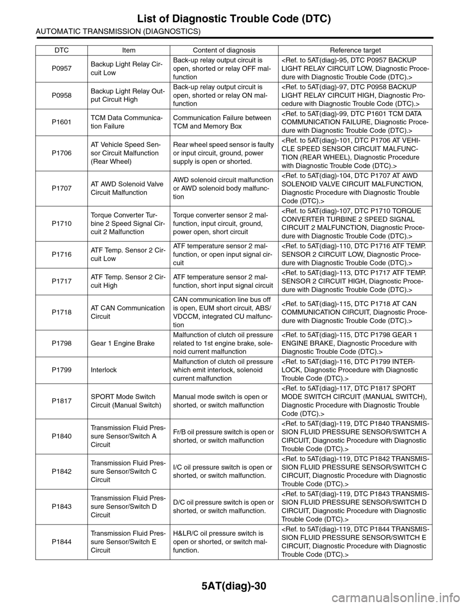
DTC Item Content of diagnosis Reference target
Page 2236 of 2453
5AT(diag)-119
Diagnostic Procedure with Diagnostic Trouble Code (DTC)
AUTOMATIC TRANSMISSION (DIAGNOSTICS)
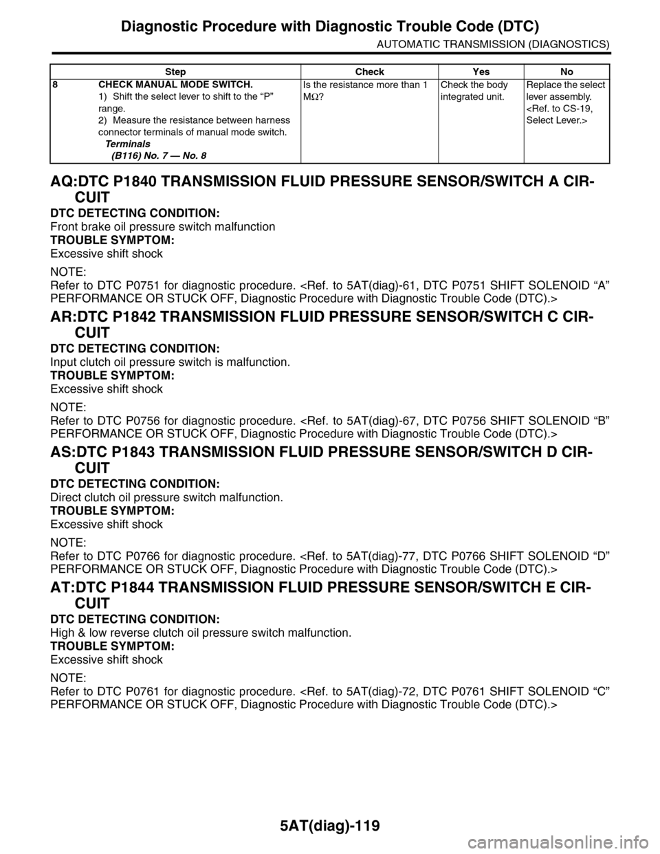
AQ:DTC P1840 TRANSMISSION FLUID PRESSURE SENSOR/SWITCH A CIR-
CUIT
DTC DETECTING CONDITION:
Front brake oil pressure switch malfunction
TROUBLE SYMPTOM:
Excessive shift shock
NOTE:
Refer to DTC P0751 for diagnostic procedure.
AR:DTC P1842 TRANSMISSION FLUID PRESSURE SENSOR/SWITCH C CIR-
CUIT
DTC DETECTING CONDITION:
Input clutch oil pressure switch is malfunction.
TROUBLE SYMPTOM:
Excessive shift shock
NOTE:
Refer to DTC P0756 for diagnostic procedure.
AS:DTC P1843 TRANSMISSION FLUID PRESSURE SENSOR/SWITCH D CIR-
CUIT
DTC DETECTING CONDITION:
Direct clutch oil pressure switch malfunction.
TROUBLE SYMPTOM:
Excessive shift shock
NOTE:
Refer to DTC P0766 for diagnostic procedure.
AT:DTC P1844 TRANSMISSION FLUID PRESSURE SENSOR/SWITCH E CIR-
CUIT
DTC DETECTING CONDITION:
High & low reverse clutch oil pressure switch malfunction.
TROUBLE SYMPTOM:
Excessive shift shock
NOTE:
Refer to DTC P0761 for diagnostic procedure.
8CHECK MANUAL MODE SWITCH.
1) Shift the select lever to shift to the “P”
range.
2) Measure the resistance between harness
connector terminals of manual mode switch.
Te r m i n a l s
(B116) No. 7 — No. 8
Is the resistance more than 1
MΩ?
Check the body
integrated unit.
Replace the select
lever assembly.
Step Check Yes No
Page 2245 of 2453
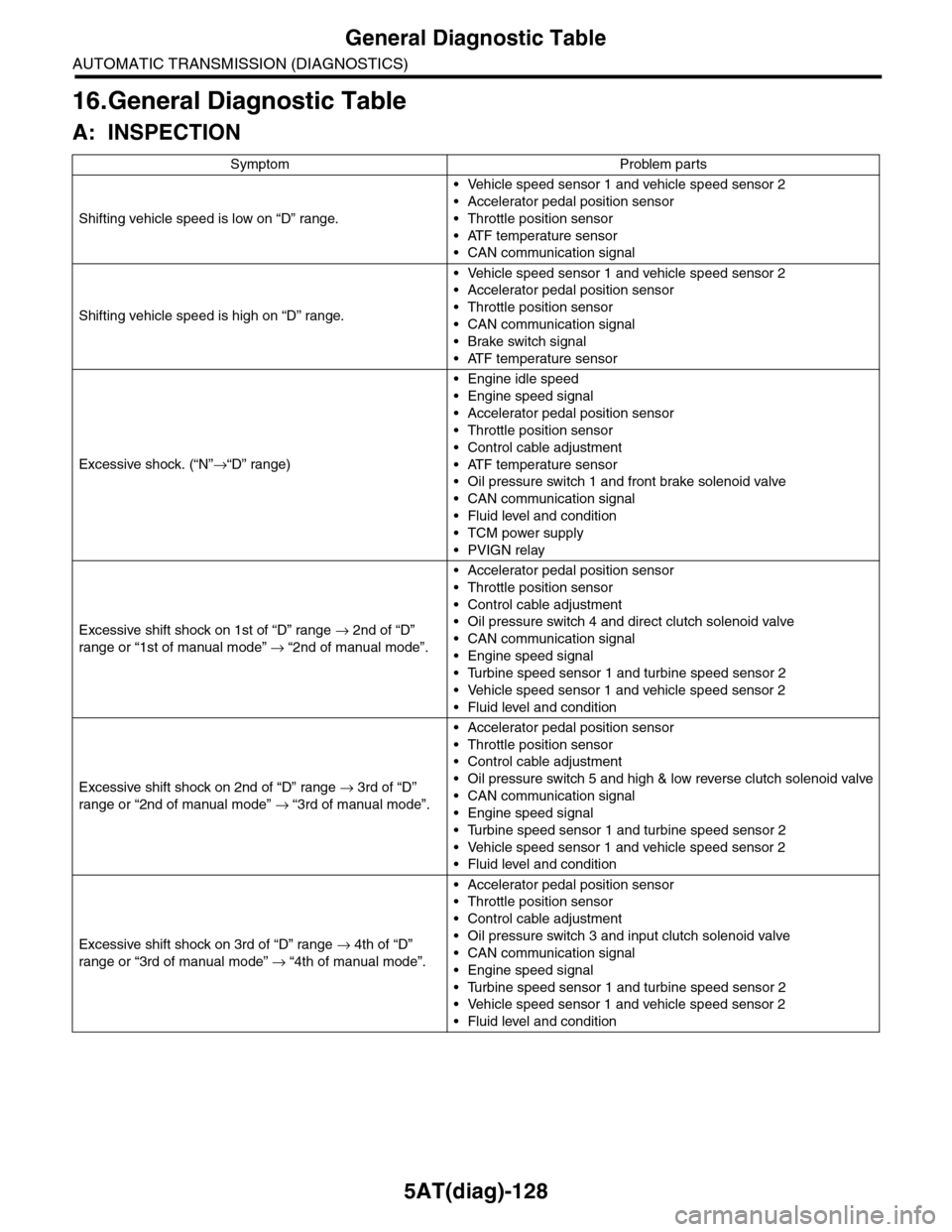
5AT(diag)-128
General Diagnostic Table
AUTOMATIC TRANSMISSION (DIAGNOSTICS)
16.General Diagnostic Table
A: INSPECTION
Symptom Problem parts
Shifting vehicle speed is low on “D” range.
•Vehicle speed sensor 1 and vehicle speed sensor 2
•Accelerator pedal position sensor
•Throttle position sensor
•ATF temperature sensor
•CAN communication signal
Shifting vehicle speed is high on “D” range.
•Vehicle speed sensor 1 and vehicle speed sensor 2
•Accelerator pedal position sensor
•Throttle position sensor
•CAN communication signal
•Brake switch signal
•ATF temperature sensor
Excessive shock. (“N”→“D” range)
•Engine idle speed
•Engine speed signal
•Accelerator pedal position sensor
•Throttle position sensor
•Control cable adjustment
•ATF temperature sensor
•Oil pressure switch 1 and front brake solenoid valve
•CAN communication signal
•Fluid level and condition
•TCM power supply
•PVIGN relay
Excessive shift shock on 1st of “D” range → 2nd of “D”
range or “1st of manual mode” → “2nd of manual mode”.
•Accelerator pedal position sensor
•Throttle position sensor
•Control cable adjustment
•Oil pressure switch 4 and direct clutch solenoid valve
•CAN communication signal
•Engine speed signal
•Turbine speed sensor 1 and turbine speed sensor 2
•Vehicle speed sensor 1 and vehicle speed sensor 2
•Fluid level and condition
Excessive shift shock on 2nd of “D” range → 3rd of “D”
range or “2nd of manual mode” → “3rd of manual mode”.
•Accelerator pedal position sensor
•Throttle position sensor
•Control cable adjustment
•Oil pressure switch 5 and high & low reverse clutch solenoid valve
•CAN communication signal
•Engine speed signal
•Turbine speed sensor 1 and turbine speed sensor 2
•Vehicle speed sensor 1 and vehicle speed sensor 2
•Fluid level and condition
Excessive shift shock on 3rd of “D” range → 4th of “D”
range or “3rd of manual mode” → “4th of manual mode”.
•Accelerator pedal position sensor
•Throttle position sensor
•Control cable adjustment
•Oil pressure switch 3 and input clutch solenoid valve
•CAN communication signal
•Engine speed signal
•Turbine speed sensor 1 and turbine speed sensor 2
•Vehicle speed sensor 1 and vehicle speed sensor 2
•Fluid level and condition
Page 2246 of 2453
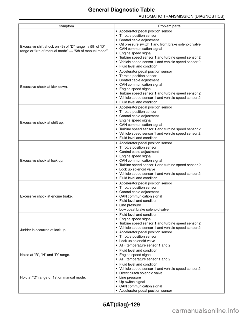
5AT(diag)-129
General Diagnostic Table
AUTOMATIC TRANSMISSION (DIAGNOSTICS)
Excessive shift shock on 4th of “D” range → 5th of “D”
range or “4th of manual mode” → “5th of manual mode”.
•Accelerator pedal position sensor
•Throttle position sensor
•Control cable adjustment
•Oil pressure switch 1 and front brake solenoid valve
•CAN communication signal
•Engine speed signal
•Turbine speed sensor 1 and turbine speed sensor 2
•Vehicle speed sensor 1 and vehicle speed sensor 2
•Fluid level and condition
Excessive shock at kick down.
•Accelerator pedal position sensor
•Throttle position sensor
•Control cable adjustment
•CAN communication signal
•Engine speed signal
•Turbine speed sensor 1 and turbine speed sensor 2
•Vehicle speed sensor 1 and vehicle speed sensor 2
•Fluid level and condition
Excessive shock at shift up.
•Accelerator pedal position sensor
•Throttle position sensor
•Control cable adjustment
•Engine speed signal
•CAN communication signal
•Turbine speed sensor 1 and turbine speed sensor 2
•Vehicle speed sensor 1 and vehicle speed sensor 2
•Fluid level and condition
Excessive shock at lock up.
•Accelerator pedal position sensor
•Throttle position sensor
•Control cable adjustment
•Engine speed signal
•CAN communication signal
•Turbine speed sensor 1 and turbine speed sensor 2
•Lock up solenoid valve
•Vehicle speed sensor 1 and vehicle speed sensor 2
•Fluid level and condition
Excessive shock at engine brake.
•Accelerator pedal position sensor
•Throttle position sensor
•Control cable adjustment
•CAN communication signal
•Fluid level and condition
•Line pressure
•Low coast brake solenoid valve
Judder is occurred at lock up.
•Fluid level and condition
•Engine speed signal
•Turbine speed sensor 1 and turbine speed sensor 2
•Vehicle speed sensor 1 and vehicle speed sensor 2
•Accelerator pedal position sensor
•Throttle position sensor
•Lock up solenoid valve
•ATF temperature sensor 1 and 2
Noise at “R”, “N” and “D” range.
•Fluid level and condition
•Engine speed signal
•ATF temperature sensor 1 and 2
Hold at “D” range or 1st on manual mode.
•Fluid level and condition
•Vehicle speed sensor 1 and vehicle speed sensor 2
•Direct clutch solenoid valve
•Line pressure
•Up switch signal
•CAN communication signal
•Accelerator pedal position sensor
Symptom Problem parts
Page 2247 of 2453
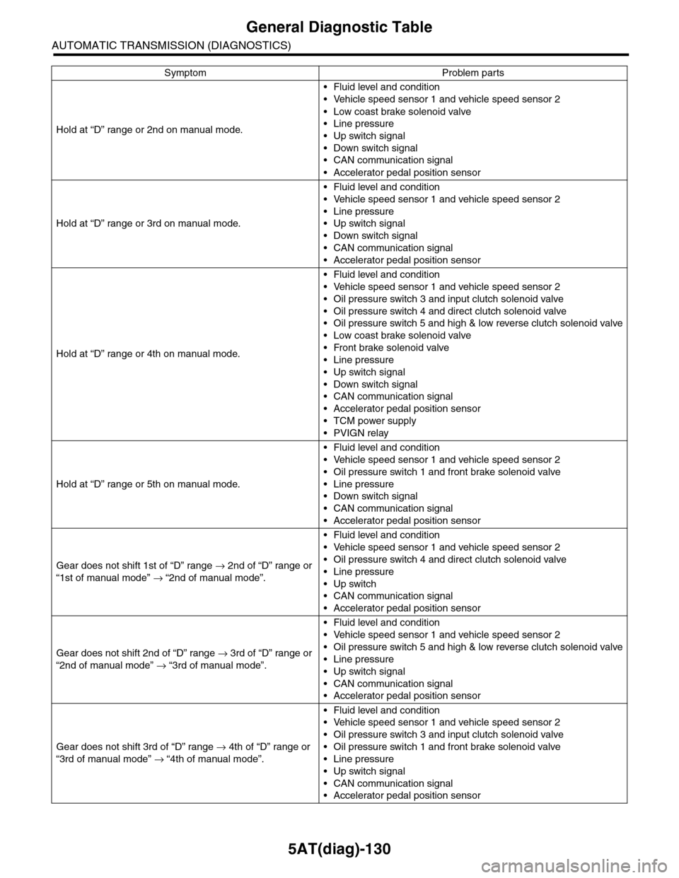
5AT(diag)-130
General Diagnostic Table
AUTOMATIC TRANSMISSION (DIAGNOSTICS)
Hold at “D” range or 2nd on manual mode.
•Fluid level and condition
•Vehicle speed sensor 1 and vehicle speed sensor 2
•Low coast brake solenoid valve
•Line pressure
•Up switch signal
•Down switch signal
•CAN communication signal
•Accelerator pedal position sensor
Hold at “D” range or 3rd on manual mode.
•Fluid level and condition
•Vehicle speed sensor 1 and vehicle speed sensor 2
•Line pressure
•Up switch signal
•Down switch signal
•CAN communication signal
•Accelerator pedal position sensor
Hold at “D” range or 4th on manual mode.
•Fluid level and condition
•Vehicle speed sensor 1 and vehicle speed sensor 2
•Oil pressure switch 3 and input clutch solenoid valve
•Oil pressure switch 4 and direct clutch solenoid valve
•Oil pressure switch 5 and high & low reverse clutch solenoid valve
•Low coast brake solenoid valve
•Front brake solenoid valve
•Line pressure
•Up switch signal
•Down switch signal
•CAN communication signal
•Accelerator pedal position sensor
•TCM power supply
•PVIGN relay
Hold at “D” range or 5th on manual mode.
•Fluid level and condition
•Vehicle speed sensor 1 and vehicle speed sensor 2
•Oil pressure switch 1 and front brake solenoid valve
•Line pressure
•Down switch signal
•CAN communication signal
•Accelerator pedal position sensor
Gear does not shift 1st of “D” range → 2nd of “D” range or
“1st of manual mode” → “2nd of manual mode”.
•Fluid level and condition
•Vehicle speed sensor 1 and vehicle speed sensor 2
•Oil pressure switch 4 and direct clutch solenoid valve
•Line pressure
•Up switch
•CAN communication signal
•Accelerator pedal position sensor
Gear does not shift 2nd of “D” range → 3rd of “D” range or
“2nd of manual mode” → “3rd of manual mode”.
•Fluid level and condition
•Vehicle speed sensor 1 and vehicle speed sensor 2
•Oil pressure switch 5 and high & low reverse clutch solenoid valve
•Line pressure
•Up switch signal
•CAN communication signal
•Accelerator pedal position sensor
Gear does not shift 3rd of “D” range → 4th of “D” range or
“3rd of manual mode” → “4th of manual mode”.
•Fluid level and condition
•Vehicle speed sensor 1 and vehicle speed sensor 2
•Oil pressure switch 3 and input clutch solenoid valve
•Oil pressure switch 1 and front brake solenoid valve
•Line pressure
•Up switch signal
•CAN communication signal
•Accelerator pedal position sensor
Symptom Problem parts
Page 2248 of 2453
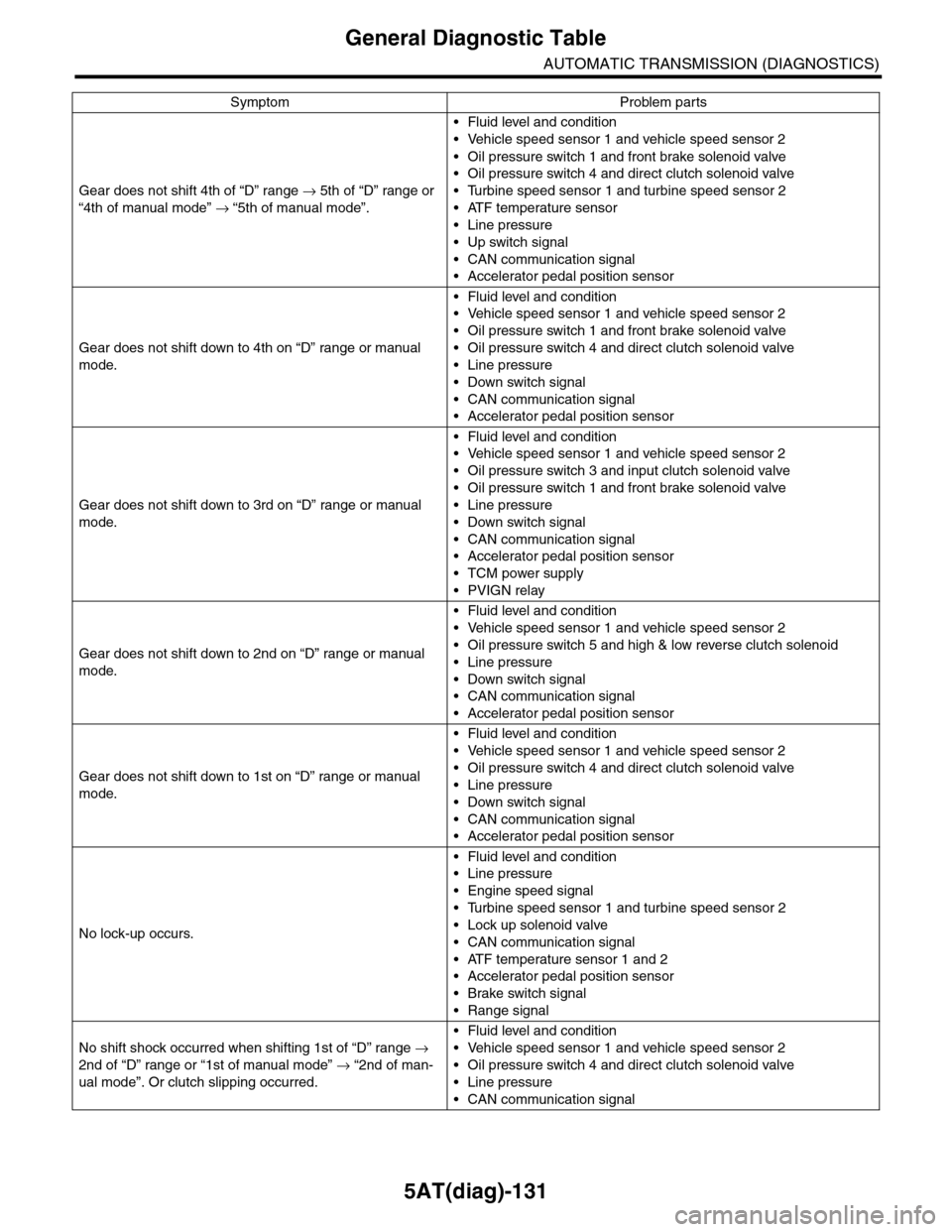
5AT(diag)-131
General Diagnostic Table
AUTOMATIC TRANSMISSION (DIAGNOSTICS)
Gear does not shift 4th of “D” range → 5th of “D” range or
“4th of manual mode” → “5th of manual mode”.
•Fluid level and condition
•Vehicle speed sensor 1 and vehicle speed sensor 2
•Oil pressure switch 1 and front brake solenoid valve
•Oil pressure switch 4 and direct clutch solenoid valve
•Turbine speed sensor 1 and turbine speed sensor 2
•ATF temperature sensor
•Line pressure
•Up switch signal
•CAN communication signal
•Accelerator pedal position sensor
Gear does not shift down to 4th on “D” range or manual
mode.
•Fluid level and condition
•Vehicle speed sensor 1 and vehicle speed sensor 2
•Oil pressure switch 1 and front brake solenoid valve
•Oil pressure switch 4 and direct clutch solenoid valve
•Line pressure
•Down switch signal
•CAN communication signal
•Accelerator pedal position sensor
Gear does not shift down to 3rd on “D” range or manual
mode.
•Fluid level and condition
•Vehicle speed sensor 1 and vehicle speed sensor 2
•Oil pressure switch 3 and input clutch solenoid valve
•Oil pressure switch 1 and front brake solenoid valve
•Line pressure
•Down switch signal
•CAN communication signal
•Accelerator pedal position sensor
•TCM power supply
•PVIGN relay
Gear does not shift down to 2nd on “D” range or manual
mode.
•Fluid level and condition
•Vehicle speed sensor 1 and vehicle speed sensor 2
•Oil pressure switch 5 and high & low reverse clutch solenoid
•Line pressure
•Down switch signal
•CAN communication signal
•Accelerator pedal position sensor
Gear does not shift down to 1st on “D” range or manual
mode.
•Fluid level and condition
•Vehicle speed sensor 1 and vehicle speed sensor 2
•Oil pressure switch 4 and direct clutch solenoid valve
•Line pressure
•Down switch signal
•CAN communication signal
•Accelerator pedal position sensor
No lock-up occurs.
•Fluid level and condition
•Line pressure
•Engine speed signal
•Turbine speed sensor 1 and turbine speed sensor 2
•Lock up solenoid valve
•CAN communication signal
•ATF temperature sensor 1 and 2
•Accelerator pedal position sensor
•Brake switch signal
•Range signal
No shift shock occurred when shifting 1st of “D” range →
2nd of “D” range or “1st of manual mode” → “2nd of man-
ual mode”. Or clutch slipping occurred.
•Fluid level and condition
•Vehicle speed sensor 1 and vehicle speed sensor 2
•Oil pressure switch 4 and direct clutch solenoid valve
•Line pressure
•CAN communication signal
Symptom Problem parts