Page 1778 of 2453
GD(H6DO)-166
Diagnostic Trouble Code (DTC) Detecting Criteria
GENERAL DESCRIPTION
6. MALFUNCTION INDICATOR LIGHT CLEAR CONDITIONS
•When the OK driving cycle is completed 3 times in a row
•When “Clear Memory” is performed
7. FAIL SAFE
Judgment of heavy fuel: Not allowed to make the judgment of heavy fuel
8. ECM OPERATION AT DTC SETTING
Memorize the freeze frame data. (For test mode $02)
Page 1779 of 2453
GD(H6DO)-167
Diagnostic Trouble Code (DTC) Detecting Criteria
GENERAL DESCRIPTION
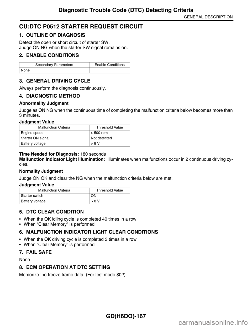
CU:DTC P0512 STARTER REQUEST CIRCUIT
1. OUTLINE OF DIAGNOSIS
Detect the open or short circuit of starter SW.
Judge ON NG when the starter SW signal remains on.
2. ENABLE CONDITIONS
3. GENERAL DRIVING CYCLE
Always perform the diagnosis continuously.
4. DIAGNOSTIC METHOD
Abnormality Judgment
Judge as ON NG when the continuous time of completing the malfunction criteria below becomes more than
3 minutes.
Time Needed for Diagnosis: 180 seconds
Malfunction Indicator Light Illumination: Illuminates when malfunctions occur in 2 continuous driving cy-
cles.
Normality Judgment
Judge ON OK and clear the NG when the malfunction criteria below are met.
5. DTC CLEAR CONDITION
•When the OK idling cycle is completed 40 times in a row
•When “Clear Memory” is performed
6. MALFUNCTION INDICATOR LIGHT CLEAR CONDITIONS
•When the OK driving cycle is completed 3 times in a row
•When “Clear Memory” is performed
7. FAIL SAFE
None
8. ECM OPERATION AT DTC SETTING
Memorize the freeze frame data. (For test mode $02)
Secondary Parameters Enable Conditions
None
Judgment Value
Malfunction Criteria Threshold Value
Engine speed > 500 rpm
Starter ON signal Not detected
Battery voltage > 8 V
Judgment Value
Malfunction Criteria Threshold Value
Starter switch ON
Battery voltage > 8 V
Page 1781 of 2453
GD(H6DO)-169
Diagnostic Trouble Code (DTC) Detecting Criteria
GENERAL DESCRIPTION
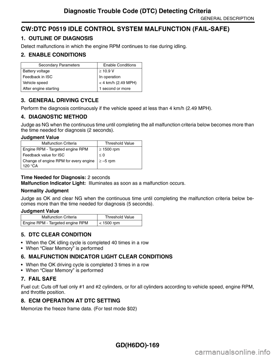
CW:DTC P0519 IDLE CONTROL SYSTEM MALFUNCTION (FAIL-SAFE)
1. OUTLINE OF DIAGNOSIS
Detect malfunctions in which the engine RPM continues to rise during idling.
2. ENABLE CONDITIONS
3. GENERAL DRIVING CYCLE
Perform the diagnosis continuously if the vehicle speed at less than 4 km/h (2.49 MPH).
4. DIAGNOSTIC METHOD
Judge as NG when the continuous time until completing the all malfunction criteria below becomes more than
the time needed for diagnosis (2 seconds).
Time Needed for Diagnosis: 2 seconds
Malfunction Indicator Light: Illuminates as soon as a malfunction occurs.
Normality Judgment
Judge as OK and clear NG when the continuous time until completing the malfunction criteria below be-
comes more than the time needed for diagnosis (5 seconds).
5. DTC CLEAR CONDITION
•When the OK idling cycle is completed 40 times in a row
•When “Clear Memory” is performed
6. MALFUNCTION INDICATOR LIGHT CLEAR CONDITIONS
•When the OK driving cycle is completed 3 times in a row
•When “Clear Memory” is performed
7. FAIL SAFE
Fuel cut: Cuts off fuel only #1 and #2 cylinders, or for all cylinders according to vehicle speed, engine RPM,
and throttle position.
8. ECM OPERATION AT DTC SETTING
Memorize the freeze frame data. (For test mode $02)
Secondary Parameters Enable Conditions
Battery voltage≥ 10.9 V
Feedback in ISC In operation
Ve h i c l e s p e e d < 4 k m / h ( 2 . 4 9 M P H )
After engine starting 1 second or more
Judgment Value
Malfunction Criteria Threshold Value
Engine RPM - Targeted engine RPM≥ 1500 rpm
Feedback value for ISC≤ 0
Change of engine RPM for every engine
120 °CA
≥ –5 rpm
Judgment Value
Malfunction Criteria Threshold Value
Engine RPM - Targeted engine RPM < 1500 rpm
Page 1782 of 2453
GD(H6DO)-170
Diagnostic Trouble Code (DTC) Detecting Criteria
GENERAL DESCRIPTION
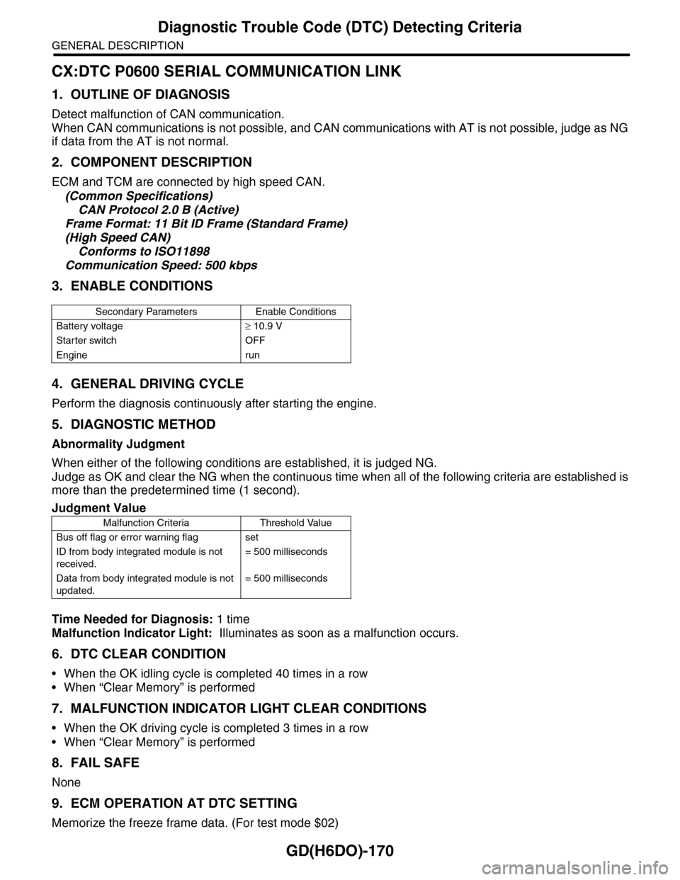
CX:DTC P0600 SERIAL COMMUNICATION LINK
1. OUTLINE OF DIAGNOSIS
Detect malfunction of CAN communication.
When CAN communications is not possible, and CAN communications with AT is not possible, judge as NG
if data from the AT is not normal.
2. COMPONENT DESCRIPTION
ECM and TCM are connected by high speed CAN.
(Common Specifications)
CAN Protocol 2.0 B (Active)
Frame Format: 11 Bit ID Frame (Standard Frame)
(High Speed CAN)
Conforms to ISO11898
Communication Speed: 500 kbps
3. ENABLE CONDITIONS
4. GENERAL DRIVING CYCLE
Perform the diagnosis continuously after starting the engine.
5. DIAGNOSTIC METHOD
Abnormality Judgment
When either of the following conditions are established, it is judged NG.
Judge as OK and clear the NG when the continuous time when all of the following criteria are established is
more than the predetermined time (1 second).
Time Needed for Diagnosis: 1 time
Malfunction Indicator Light: Illuminates as soon as a malfunction occurs.
6. DTC CLEAR CONDITION
•When the OK idling cycle is completed 40 times in a row
•When “Clear Memory” is performed
7. MALFUNCTION INDICATOR LIGHT CLEAR CONDITIONS
•When the OK driving cycle is completed 3 times in a row
•When “Clear Memory” is performed
8. FAIL SAFE
None
9. ECM OPERATION AT DTC SETTING
Memorize the freeze frame data. (For test mode $02)
Secondary Parameters Enable Conditions
Battery voltage≥ 10.9 V
Starter switch OFF
Engine run
Judgment Value
Malfunction Criteria Threshold Value
Bus off flag or error warning flag set
ID from body integrated module is not
received.
= 500 milliseconds
Data from body integrated module is not
updated.
= 500 milliseconds
Page 1783 of 2453
GD(H6DO)-171
Diagnostic Trouble Code (DTC) Detecting Criteria
GENERAL DESCRIPTION
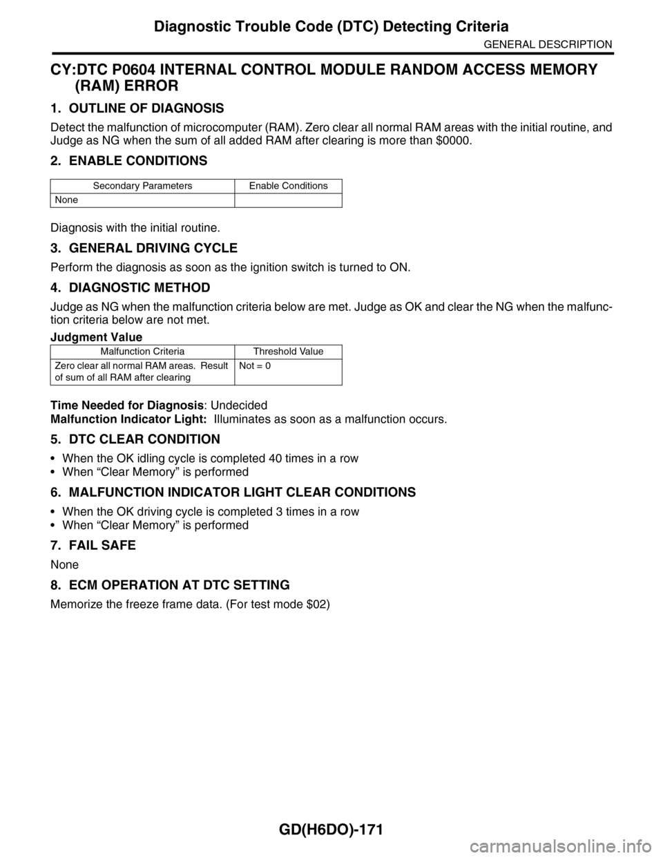
CY:DTC P0604 INTERNAL CONTROL MODULE RANDOM ACCESS MEMORY
(RAM) ERROR
1. OUTLINE OF DIAGNOSIS
Detect the malfunction of microcomputer (RAM). Zero clear all normal RAM areas with the initial routine, and
Judge as NG when the sum of all added RAM after clearing is more than $0000.
2. ENABLE CONDITIONS
Diagnosis with the initial routine.
3. GENERAL DRIVING CYCLE
Perform the diagnosis as soon as the ignition switch is turned to ON.
4. DIAGNOSTIC METHOD
Judge as NG when the malfunction criteria below are met. Judge as OK and clear the NG when the malfunc-
tion criteria below are not met.
Time Needed for Diagnosis: Undecided
Malfunction Indicator Light: Illuminates as soon as a malfunction occurs.
5. DTC CLEAR CONDITION
•When the OK idling cycle is completed 40 times in a row
•When “Clear Memory” is performed
6. MALFUNCTION INDICATOR LIGHT CLEAR CONDITIONS
•When the OK driving cycle is completed 3 times in a row
•When “Clear Memory” is performed
7. FAIL SAFE
None
8. ECM OPERATION AT DTC SETTING
Memorize the freeze frame data. (For test mode $02)
Secondary Parameters Enable Conditions
None
Judgment Value
Malfunction Criteria Threshold Value
Zero clear all normal RAM areas. Result
of sum of all RAM after clearing
Not = 0
Page 1784 of 2453
GD(H6DO)-172
Diagnostic Trouble Code (DTC) Detecting Criteria
GENERAL DESCRIPTION
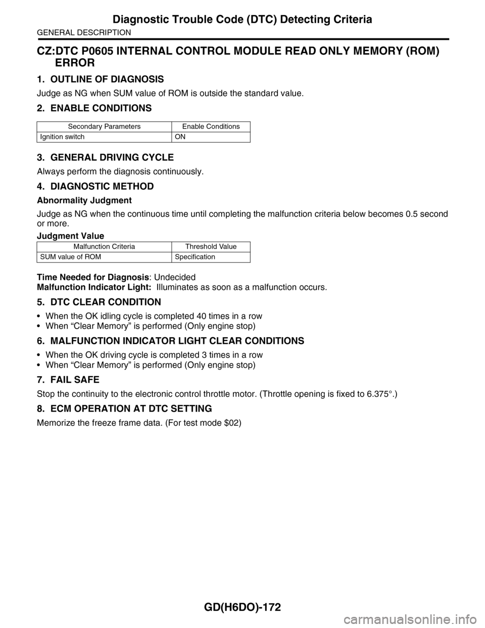
CZ:DTC P0605 INTERNAL CONTROL MODULE READ ONLY MEMORY (ROM)
ERROR
1. OUTLINE OF DIAGNOSIS
Judge as NG when SUM value of ROM is outside the standard value.
2. ENABLE CONDITIONS
3. GENERAL DRIVING CYCLE
Always perform the diagnosis continuously.
4. DIAGNOSTIC METHOD
Abnormality Judgment
Judge as NG when the continuous time until completing the malfunction criteria below becomes 0.5 second
or more.
Time Needed for Diagnosis: Undecided
Malfunction Indicator Light: Illuminates as soon as a malfunction occurs.
5. DTC CLEAR CONDITION
•When the OK idling cycle is completed 40 times in a row
•When “Clear Memory” is performed (Only engine stop)
6. MALFUNCTION INDICATOR LIGHT CLEAR CONDITIONS
•When the OK driving cycle is completed 3 times in a row
•When “Clear Memory” is performed (Only engine stop)
7. FAIL SAFE
Stop the continuity to the electronic control throttle motor. (Throttle opening is fixed to 6.375°.)
8. ECM OPERATION AT DTC SETTING
Memorize the freeze frame data. (For test mode $02)
Secondary Parameters Enable Conditions
Ignition switch ON
Judgment Value
Malfunction Criteria Threshold Value
SUM value of ROM Specification
Page 1785 of 2453
GD(H6DO)-173
Diagnostic Trouble Code (DTC) Detecting Criteria
GENERAL DESCRIPTION
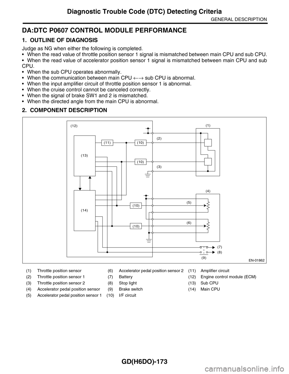
DA:DTC P0607 CONTROL MODULE PERFORMANCE
1. OUTLINE OF DIAGNOSIS
Judge as NG when either the following is completed.
•When the read value of throttle position sensor 1 signal is mismatched between main CPU and sub CPU.
•When the read value of accelerator position sensor 1 signal is mismatched between main CPU and sub
CPU.
•When the sub CPU operates abnormally.
•When the communication between main CPU ←→ sub CPU is abnormal.
•When the input amplifier circuit of throttle position sensor 1 is abnormal.
•When the cruise control cannot be canceled correctly.
•When the signal of brake SW1 and 2 is mismatched.
•When the directed angle from the main CPU is abnormal.
2. COMPONENT DESCRIPTION
(1) Throttle position sensor (6) Accelerator pedal position sensor 2 (11) Amplifier circuit
(2) Throttle position sensor 1 (7) Battery (12) Engine control module (ECM)
(3) Throttle position sensor 2 (8) Stop light (13) Sub CPU
(4) Accelerator pedal position sensor (9) Brake switch (14) Main CPU
(5) Accelerator pedal position sensor 1 (10) I/F circuit
EN-01862
(1)
(4)
(2)
(3)
(5)
(6)
(7)
(8)
(9)
(12)
(11)(10)
(10)
(10)
(10)
(13)
(14)
Page 1786 of 2453
GD(H6DO)-174
Diagnostic Trouble Code (DTC) Detecting Criteria
GENERAL DESCRIPTION
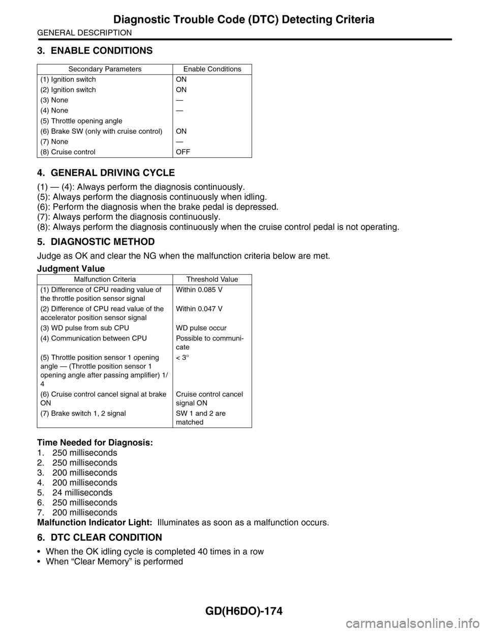
3. ENABLE CONDITIONS
4. GENERAL DRIVING CYCLE
(1) — (4): Always perform the diagnosis continuously.
(5): Always perform the diagnosis continuously when idling.
(6): Perform the diagnosis when the brake pedal is depressed.
(7): Always perform the diagnosis continuously.
(8): Always perform the diagnosis continuously when the cruise control pedal is not operating.
5. DIAGNOSTIC METHOD
Judge as OK and clear the NG when the malfunction criteria below are met.
Time Needed for Diagnosis:
1. 250 milliseconds
2. 250 milliseconds
3. 200 milliseconds
4. 200 milliseconds
5. 24 milliseconds
6. 250 milliseconds
7. 200 milliseconds
Malfunction Indicator Light: Illuminates as soon as a malfunction occurs.
6. DTC CLEAR CONDITION
•When the OK idling cycle is completed 40 times in a row
•When “Clear Memory” is performed
Secondary Parameters Enable Conditions
(1) Ignition switch ON
(2) Ignition switch ON
(3) None —
(4) None —
(5) Throttle opening angle
(6) Brake SW (only with cruise control) ON
(7) None —
(8) Cruise control OFF
Judgment Value
Malfunction Criteria Threshold Value
(1) Difference of CPU reading value of
the throttle position sensor signal
Within 0.085 V
(2) Difference of CPU read value of the
accelerator position sensor signal
Within 0.047 V
(3) WD pulse from sub CPU WD pulse occur
(4) Communication between CPU Possible to communi-
cate
(5) Throttle position sensor 1 opening
angle — (Throttle position sensor 1
opening angle after passing amplifier) 1/
4
< 3°
(6) Cruise control cancel signal at brake
ON
Cruise control cancel
signal ON
(7) Brake switch 1, 2 signal SW 1 and 2 are
matched