2009 SUBARU TRIBECA height
[x] Cancel search: heightPage 1131 of 2453
CO(H6DO)-12
Engine Coolant
COOLING
2. PROCEDURE TO ADJUST THE CON-
CENTRATION OF THE COOLANT
To adjust the concentration of coolant according to
temperature, find the proper fluid concentration in
the above diagram and replace the necessary
amount of coolant with an undiluted solution of
SUBARU Genuine Coolant (concentration 50%).
The amount of engine coolant that should be re-
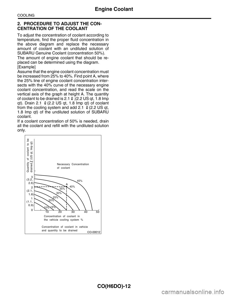
placed can be determined using the diagram.
[Example]
Assume that the engine coolant concentration must
be increased from 25% to 40%. Find point A, where
the 25% line of engine coolant concentration inter-
sects with the 40% curve of the necessary engine
coolant concentration, and read the scale on the
vertical axis of the graph at height A. The quantity
of coolant to be drained is 2.12;(2.2 US qt, 1.8 Imp
qt). Drain 2.1 2(2.2 US qt, 1.8 Imp qt) of coolant
from the cooling system and add 2.1 2(2.2 US qt,
1.8 Imp qt) of the undiluted solution of SUBARU
coolant.
If a coolant concentration of 50% is needed, drain
all the coolant and refill with the undiluted solution
only.
CO-00012
100
1
2
3
(1.1, 0.9)
(2.1, 1.8)
(3.2, 2.6)
10%15%
25%20%
30%
35%40%
45%A
20 30 40 50
Concentration of coolant in vehicieand quantity to be drained
Quantity of coolant to bedrained (US qt, Imp qt)
Necessary Concentrationof coolant
Concentration of coolant inthe vehicie cooling system %
Page 1869 of 2453
ME(H6DO)-3
General Description
MECHANICAL
Camshaft
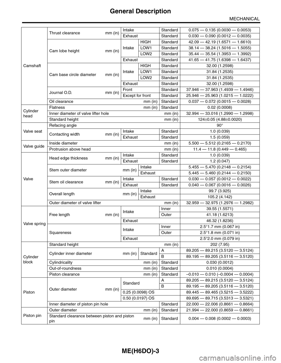
Thrust clearance mm (in)Intake Standard 0.075 — 0.135 (0.0030 — 0.0053)
Exhaust Standard 0.030 — 0.090 (0.0012 — 0.0035)
Cam lobe height mm (in)Intake
HIGH Standard 42.09 — 42.19 (1.6571 — 1.6610)
LOW1 Standard 38.14 — 38.24 (1.5016 — 1.5055)
LOW2 Standard 35.44 — 35.54 (1.3953 — 1.3992)
Exhaust Standard 41.65 — 41.75 (1.6398 — 1.6437)
Cam base circle diameter mm (in)Intake
HIGH Standard 32.00 (1.2598)
LOW1 Standard 31.84 (1.2535)
LOW2 Standard 31.84 (1.2535)
Exhaust Standard 32.00 (1.2598)
Journal O.D. mm (in)Fr o nt S ta n da r d 3 7. 9 46 — 3 7 . 96 3 ( 1 . 49 3 9 — 1. 4 9 46 )
Except for front Standard 25.946 — 25.963 (1.0215 — 1.0222)
Oil clearance mm (in) Standard 0.037 — 0.072 (0.0015 — 0.0028)
Cylinder
head
Flatness mm (in) Standard 0.02 (0.0008)
Inner diameter of valve lifter hole mm (in) 32.994 — 33.016 (1.2990 — 1.2998)
Standard height mm (in) 124±0.05 (4.88±0.0020)
Va l ve s e a t
Refacing angle90°
Contacting width mm (in)Intake Standard 1.0 (0.039)
Exhaust Standard 1.5 (0.059)
Va l ve g u i d eInside diameter mm (in) 5.500 — 5.512 (0.2165 — 0.2170)
Protrusion above head mm (in) 11.4 — 11.8 (0.449 — 0.465)
Va l ve
Head edge thickness mm (in)Intake Standard 1.0 (0.039)
Exhaust Standard 1.2 (0.047)
Stem outer diameter mm (in)Intake 5.455 — 5.470 (0.2148 — 0.2154)
Exhaust 5.445 — 5.460 (0.2144 — 0.2150)
Stem oil clearance mm (in)Intake Standard 0.030 — 0.057 (0.0012 — 0.0022)
Exhaust Standard 0.040 — 0.067 (0.0016 — 0.0026)
Overall length mm (in)Intake 99.7 (3.925)
Exhaust 105.2 (4.142)
Outer diameter of valve lifter mm (in) 32.959 — 32.975 (1.2976 — 1.2982)
Va l ve s p r i n g
Free length mm (in)IntakeInner 39.55 (1.5571)
Outer 41.18 (1.6213)
Exhaust 46.32 (1.8236)
SquarenessIntakeInner 2.5°1.7 mm (0.067 in)
Outer 2.5°1.8 mm (0.071 in)
Exhaust 2.5°2.0 mm (0.079 in)
Cylinder
block
Standard height mm (in) 202 (7.95)
Cylinder inner diameter mm (in) StandardA89.205 — 89.215 (3.5120 — 3.5124)
B89.195 — 89.205 (3.5116 — 3.5120)
Cylindricality mm (in) Standard 0.030 (0.0012)
Out-of-roundness mm (in) Standard 0.010 (0.0004)
Piston clearance mm (in) Standard –0.010 — 0.010 (–0.0004 — 0.0004)
PistonOuter diameter mm (in)
StandardA89.205 — 89.215 (3.5120 — 3.5124)
B89.195 — 89.205 (3.5116 — 3.5120)
0.25 (0.0098) OS 89.445 — 89.465 (3.5215 — 3.5222)
0.50 (0.0197) OS 89.695 — 89.715 (3.5313 — 3.5321)
Inner diameter of piston pin hole Standard 22.000 — 22.006 (0.8661 — 0.8664)
Piston pin
Outer diameter mm (in) Standard 21.994 — 22.000 (0.8659 — 0.8661)
Standard clearance between piston and piston
pinmm (in) Standard 0.004 — 0.008 (0.0002 — 0.0003)
Page 1922 of 2453
ME(H6DO)-56
Camshaft
MECHANICAL
(6) Measure the widest point of the plastigauge
on each journal. If oil clearance exceeds the
standard, replace the camshaft. If necessary,
replace the camshaft caps and cylinder head as
a set.
Standard:
0.037 — 0.072 mm (0.0015 — 0.0028 in)
(7) Completely remove the plastigauge.
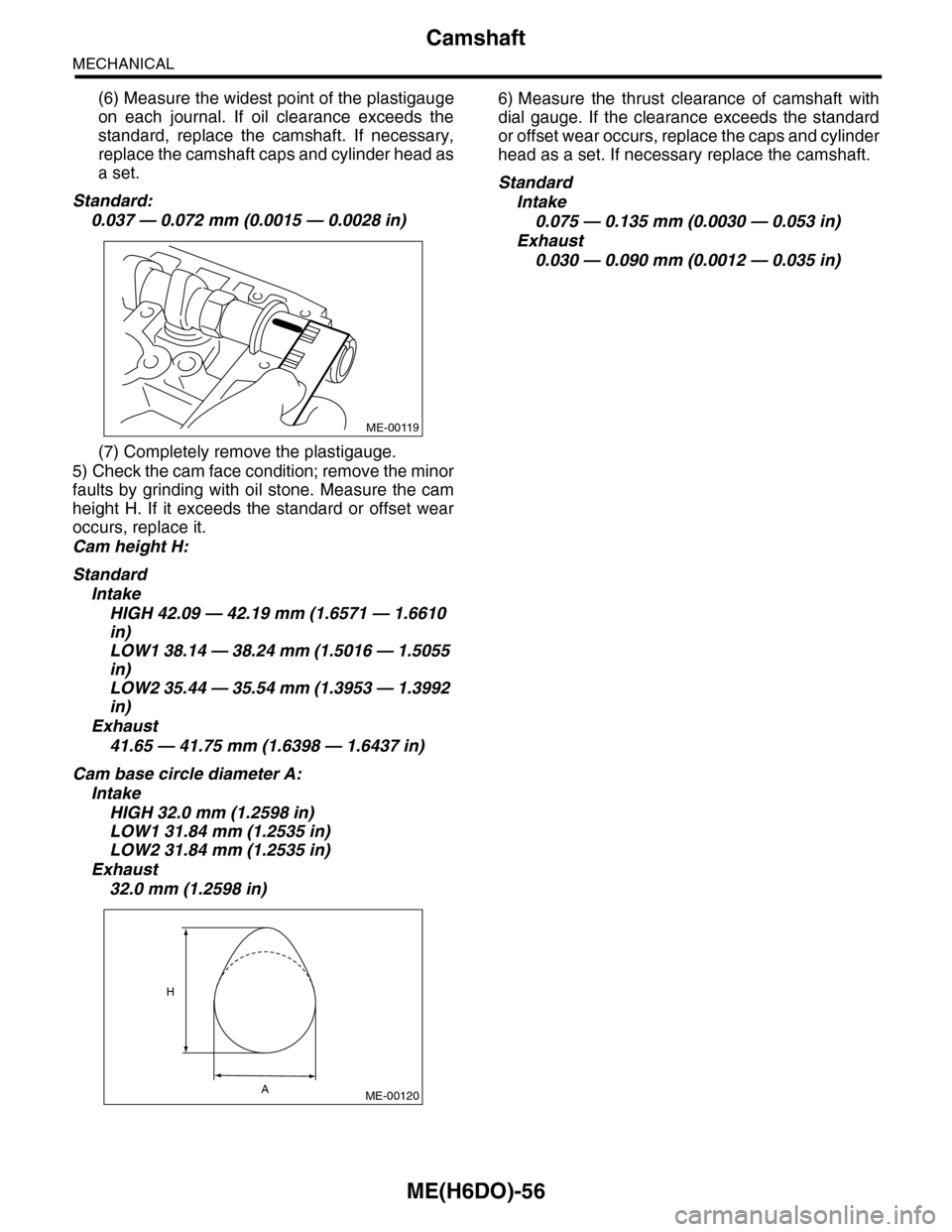
5) Check the cam face condition; remove the minor
faults by grinding with oil stone. Measure the cam
height H. If it exceeds the standard or offset wear
occurs, replace it.
Cam height H:
Standard
Intake
HIGH 42.09 — 42.19 mm (1.6571 — 1.6610
in)
LOW1 38.14 — 38.24 mm (1.5016 — 1.5055
in)
LOW2 35.44 — 35.54 mm (1.3953 — 1.3992
in)
Exhaust
41.65 — 41.75 mm (1.6398 — 1.6437 in)
Cam base circle diameter A:
Intake
HIGH 32.0 mm (1.2598 in)
LOW1 31.84 mm (1.2535 in)
LOW2 31.84 mm (1.2535 in)
Exhaust
32.0 mm (1.2598 in)
6) Measure the thrust clearance of camshaft with
dial gauge. If the clearance exceeds the standard
or offset wear occurs, replace the caps and cylinder
head as a set. If necessary replace the camshaft.
Standard
Intake
0.075 — 0.135 mm (0.0030 — 0.053 in)
Exhaust
0.030 — 0.090 mm (0.0012 — 0.035 in)
ME-00119
ME-00120
H
A
Page 1925 of 2453
ME(H6DO)-59
Cylinder Head
MECHANICAL
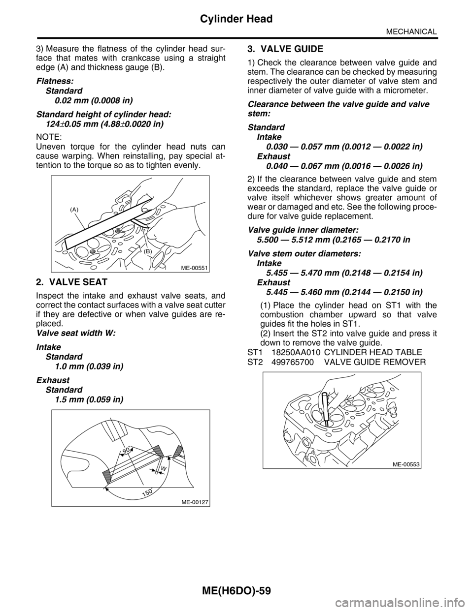
3) Measure the flatness of the cylinder head sur-
face that mates with crankcase using a straight
edge (A) and thickness gauge (B).
Flatness:
Standard
0.02 mm (0.0008 in)
Standard height of cylinder head:
124±0.05 mm (4.88±0.0020 in)
NOTE:
Uneven torque for the cylinder head nuts can
cause warping. When reinstalling, pay special at-
tention to the torque so as to tighten evenly.
2. VALVE SEAT
Inspect the intake and exhaust valve seats, and
correct the contact surfaces with a valve seat cutter
if they are defective or when valve guides are re-
placed.
Valve seat width W:
Intake
Standard
1.0 mm (0.039 in)
Exhaust
Standard
1.5 mm (0.059 in)
3. VALVE GUIDE
1) Check the clearance between valve guide and
stem. The clearance can be checked by measuring
respectively the outer diameter of valve stem and
inner diameter of valve guide with a micrometer.
Clearance between the valve guide and valve
stem:
Standard
Intake
0.030 — 0.057 mm (0.0012 — 0.0022 in)
Exhaust
0.040 — 0.067 mm (0.0016 — 0.0026 in)
2) If the clearance between valve guide and stem
exceeds the standard, replace the valve guide or
valve itself whichever shows greater amount of
wear or damaged and etc. See the following proce-
dure for valve guide replacement.
Valve guide inner diameter:
5.500 — 5.512 mm (0.2165 — 0.2170 in
Valve stem outer diameters:
Intake
5.455 — 5.470 mm (0.2148 — 0.2154 in)
Exhaust
5.445 — 5.460 mm (0.2144 — 0.2150 in)
(1) Place the cylinder head on ST1 with the
combustion chamber upward so that valve
guides fit the holes in ST1.
(2) Insert the ST2 into valve guide and press it
down to remove the valve guide.
ST1 18250AA010 CYLINDER HEAD TABLE
ST2 499765700 VALVE GUIDE REMOVER
(A)
(B)
ME-00551
ME-00127
WME-00553
Page 1937 of 2453
ME(H6DO)-71
Cylinder Block
MECHANICAL
E: INSPECTION
1. CYLINDER BLOCK
1) Visually check for cracks and damage. Especial-
ly, inspect the important parts using liquid pene-
trant tester.
2) Check the oil passages for clogging.
3) Inspect the crankcase surface that mates with
cylinder head for warping by using a straight edge.
Standard height of cylinder block:
202 mm (7.95 in)
2. CYLINDER AND PISTON
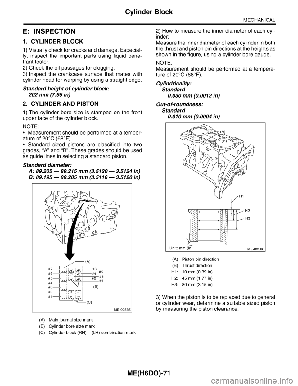
1) The cylinder bore size is stamped on the front
upper face of the cylinder block.
NOTE:
•Measurement should be performed at a temper-
ature of 20°C (68°F).
•Standard sized pistons are classified into two
grades, “A” and “B”. These grades should be used
as guide lines in selecting a standard piston.
Standard diameter:
A: 89.205 — 89.215 mm (3.5120 — 3.5124 in)
B: 89.195 — 89.205 mm (3.5116 — 3.5120 in)
2) How to measure the inner diameter of each cyl-
inder:
Measure the inner diameter of each cylinder in both
the thrust and piston pin directions at the heights as
shown in the figure, using a cylinder bore gauge.
NOTE:
Measurement should be performed at a tempera-
ture of 20°C (68°F).
Cylindricality:
Standard
0.030 mm (0.0012 in)
Out-of-roundness:
Standard
0.010 mm (0.0004 in)
3) When the piston is to be replaced due to general
or cylinder wear, determine a suitable sized piston
by measuring the piston clearance.
(A) Main journal size mark
(B) Cylinder bore size mark
(C) Cylinder block (RH) – (LH) combination mark
#7 #6#5
#2#1
#4#3#6#5#4#3#2#1
BBB 2
42BAB4
(A)
(B)
(C)
ME-00585
(A) Piston pin direction
(B) Thrust direction
H1: 10 mm (0.39 in)
H2: 45 mm (1.77 in)
H3: 80 mm (3.15 in)
ME-00586
H1
H2
H3
Unit: mm (in)
(B)
(A)
Page 1938 of 2453
ME(H6DO)-72
Cylinder Block
MECHANICAL
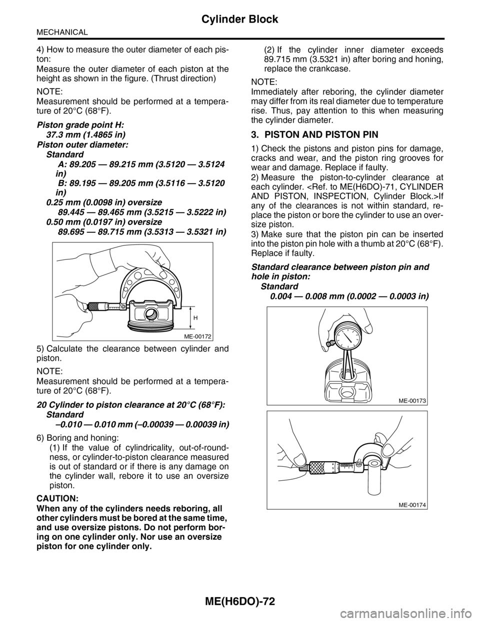
4) How to measure the outer diameter of each pis-
ton:
Measure the outer diameter of each piston at the
height as shown in the figure. (Thrust direction)
NOTE:
Measurement should be performed at a tempera-
ture of 20°C (68°F).
Piston grade point H:
37.3 mm (1.4865 in)
Piston outer diameter:
Standard
A: 89.205 — 89.215 mm (3.5120 — 3.5124
in)
B: 89.195 — 89.205 mm (3.5116 — 3.5120
in)
0.25 mm (0.0098 in) oversize
89.445 — 89.465 mm (3.5215 — 3.5222 in)
0.50 mm (0.0197 in) oversize
89.695 — 89.715 mm (3.5313 — 3.5321 in)
5) Calculate the clearance between cylinder and
piston.
NOTE:
Measurement should be performed at a tempera-
ture of 20°C (68°F).
20 Cylinder to piston clearance at 20°C (68°F):
Standard
–0.010 — 0.010 mm (–0.00039 — 0.00039 in)
6) Boring and honing:
(1) If the value of cylindricality, out-of-round-
ness, or cylinder-to-piston clearance measured
is out of standard or if there is any damage on
the cylinder wall, rebore it to use an oversize
piston.
CAUTION:
When any of the cylinders needs reboring, all
other cylinders must be bored at the same time,
and use oversize pistons. Do not perform bor-
ing on one cylinder only. Nor use an oversize
piston for one cylinder only.
(2) If the cylinder inner diameter exceeds
89.715 mm (3.5321 in) after boring and honing,
replace the crankcase.
NOTE:
Immediately after reboring, the cylinder diameter
may differ from its real diameter due to temperature
rise. Thus, pay attention to this when measuring
the cylinder diameter.
3. PISTON AND PISTON PIN
1) Check the pistons and piston pins for damage,
cracks and wear, and the piston ring grooves for
wear and damage. Replace if faulty.
2) Measure the piston-to-cylinder clearance at
each cylinder.
any of the clearances is not within standard, re-
place the piston or bore the cylinder to use an over-
size piston.
3) Make sure that the piston pin can be inserted
into the piston pin hole with a thumb at 20°C (68°F).
Replace if faulty.
Standard clearance between piston pin and
hole in piston:
Standard
0.004 — 0.008 mm (0.0002 — 0.0003 in)
ME-00172
H
ME-00173
ME-00174
Page 1998 of 2453
PM-15
Engine Coolant
PERIODIC MAINTENANCE SERVICES
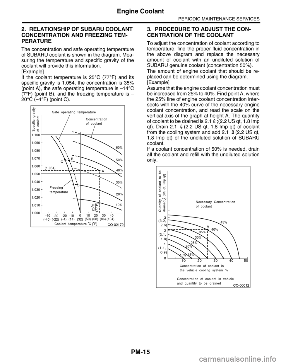
2. RELATIONSHIP OF SUBARU COOLANT
CONCENTRATION AND FREEZING TEM-
PERATURE
The concentration and safe operating temperature
of SUBARU coolant is shown in the diagram. Mea-
suring the temperature and specific gravity of the
coolant will provide this information.
[Example]
If the coolant temperature is 25°C (77°F) and its
specific gravity is 1.054, the concentration is 35%
(point A), the safe operating temperature is –14°C
(7°F) (point B), and the freezing temperature is –
20°C (–4°F) (point C).
3. PROCEDURE TO ADJUST THE CON-
CENTRATION OF THE COOLANT
To adjust the concentration of coolant according to
temperature, find the proper fluid concentration in
the above diagram and replace the necessary
amount of coolant with an undiluted solution of
SUBARU genuine coolant (concentration 50%).
The amount of engine coolant that should be re-
placed can be determined using the diagram.
[Example]
Assume that the engine coolant concentration must
be increased from 25% to 40%. Find point A, where
the 25% line of engine coolant concentration inter-
sects with the 40% curve of the necessary engine
coolant concentration, and read the scale on the
vertical axis of the graph at height A. The quantity
of coolant to be drained is 2.12;(2.2 US qt, 1.8 Imp
qt). Drain 2.1 2(2.2 US qt, 1.8 Imp qt) of coolant
from the cooling system and add 2.1 2(2.2 US qt,
1.8 Imp qt) of the undiluted solution of SUBARU
coolant.
If a coolant concentration of 50% is needed, drain
all the coolant and refill with the undiluted solution
only.
CO-02172
60%
(1.054)
1.000
1.010
1.020
1.030
1.040
1.050
1.060
1.070
1.080
1.090
1.100
Safe operating temperature
Freezingtemperature
Concentrationof coolant
Specific gravityof coolant
Coolant temperature
B
A
C
-40(-40) (-22)(-4)(14)(32)(50) (68) (86)
( F)
(104)-30-20 -10010203040
(77 F)
50%
40%
30%
20%
25 C
10%
C
CO-00012
100
1
2
3
(1.1, 0.9)
(2.1, 1.8)
(3.2, 2.6)
10%15%
25%20%
30%
35%40%
45%A
20 30 40 50
Concentration of coolant in vehicieand quantity to be drained
Quantity of coolant to bedrained (US qt, Imp qt)
Necessary Concentrationof coolant
Concentration of coolant inthe vehicie cooling system %
Page 2003 of 2453
PM-20
Brake Line
PERIODIC MAINTENANCE SERVICES
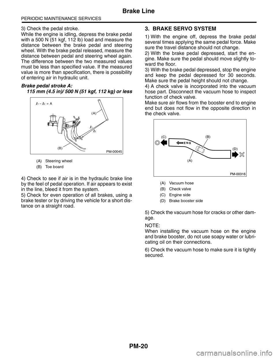
3) Check the pedal stroke.
While the engine is idling, depress the brake pedal
with a 500 N (51 kgf, 112 lb) load and measure the
distance between the brake pedal and steering
wheel. With the brake pedal released, measure the
distance between pedal and steering wheel again.
The difference between the two measured values
must be less than specified value. If the measured
value is more than specification, there is possibility
of entering air in hydraulic unit.
Brake pedal stroke A:
115 mm (4.5 in)/ 500 N (51 kgf, 112 kg) or less
4) Check to see if air is in the hydraulic brake line
by the feel of pedal operation. If air appears to exist
in the line, bleed it from the system.
5) Check for even operation of all brakes, using a
brake tester or by driving the vehicle for a short dis-
tance on a straight road.
3. BRAKE SERVO SYSTEM
1) With the engine off, depress the brake pedal
several times applying the same pedal force. Make
sure the travel distance should not change.
2) With the brake pedal depressed, start the en-
gine. Make sure the pedal should move slightly to-
ward the floor.
3) With the brake pedal depressed, stop the engine
and keep the pedal depressed for 30 seconds.
Make sure the pedal height should not change.
4) A check valve is incorporated into the vacuum
hose part. Disconnect the vacuum hose to inspect
function of check valve.
Make sure air flows from the booster end to engine
end but does not flow in the opposite direction in
the check valve.
5) Check the vacuum hose for cracks or other dam-
age.
NOTE:
When installing the vacuum hose on the engine
and brake booster, do not use soapy water or lubri-
cating oil on their connections.
6) Check the vacuum hose to make sure it is tightly
secured.
(A) Steering wheel
(B) Toe board
PM-00045(B)
(A)
= A
1
12
2
(A) Vacuum hose
(B) Check valve
(C) Engine side
(D) Brake booster side