2009 SUBARU TRIBECA height
[x] Cancel search: heightPage 804 of 2453

DI-20
Rear Differential (VA–type)
DIFFERENTIALS
1) Adjusting preload for front and rear bearings
Adjust the bearing preload between front and rear
bearings with collar and washer. Pinion height ad-
justing washer is not affected by this adjustment.
The adjustment must not be carried out with oil seal
inserted.
(1) Install the rear bearing race into the differen-
tial carrier using ST1 and ST2.
ST1 398477701 HANDLE
ST2 398477703 DRIFT 2
(2) Using the ST, install the front bearing race to
the differential carrier.
ST 499277200 INSTALLER
(3) Insert the front bearing cone.
NOTE:
Use new front bearing cone.
(4) Measure and record the thickness of pinion
adjust washer.
NOTE:
If tooth contact (drive pinion, hypoid driven gear) is
normal in the inspection before disassembling, ver-
ify that the washer is not deformed, and then re-use
the used washer.
(5) Insert the ST1 into carrier with the pinion
height adjusting washer and rear bearing cone
fitted onto it.
NOTE:
Use new rear bearing cone.
(6) Install the preload adjusting collar & washer,
front bearing cone, collar, companion flange,
and washer & self-locking nut.
ST1 18678AA000 DUMMY SHAFT
(7) Turn ST1 by hand to seat the bearing, and
measure the initial load and initial torque with a
spring scale while tightening the selflocking nut.
Select the preload adjusting washer and collar
so that the specified preload is obtained when
nut is tightened to the specified torque.
NOTE:
•Use a new self-locking nut.
•Be careful not to give excessive preload.
•When tightening the self-locking nut, lock com-
panion flange with ST2 as shown in the figure.
•Measure the preload in direction of tangent to the
flange.
ST1 18678AA000 DUMMY SHAFT
ST2 498427200 FLANGE WRENCH
Tightening torque:
191 N·m (19.5 kgf-m, 141 ft-lb)
DI-00375
ST2
ST1
DI-00376
ST
(A) Pinion height adjusting washer
(B) Preload adjusting collar
(C) Preload adjusting washer
(D) Collar
ST1DI-00377
(D)(C)(B)(A)
DI-00398
ST2
Page 805 of 2453

DI-21
Rear Differential (VA–type)
DIFFERENTIALS
Initial load:
12.7—32.2 N (1.3—3.28 kgf, 2.9—7.24 lb)
Initial torque:
0.48 — 1.22 N·m (0.045—0.124 kgf-m, 0.32—
0.9 ft-lb)
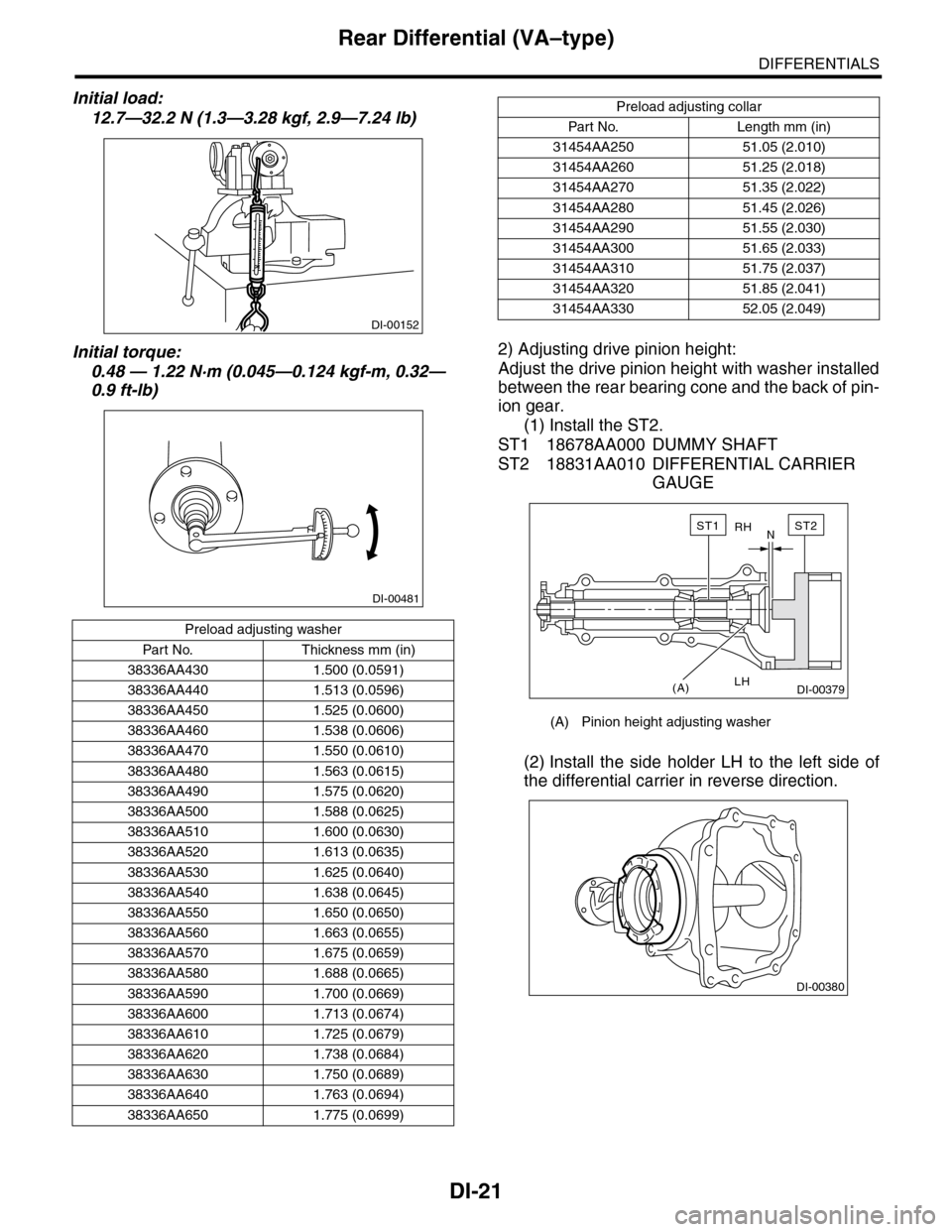
2) Adjusting drive pinion height:
Adjust the drive pinion height with washer installed
between the rear bearing cone and the back of pin-
ion gear.
(1) Install the ST2.
ST1 18678AA000 DUMMY SHAFT
ST2 18831AA010 DIFFERENTIAL CARRIER
GAUGE
(2) Install the side holder LH to the left side of
the differential carrier in reverse direction.
Preload adjusting washer
Par t No. Thickness mm (in)
38336AA430 1.500 (0.0591)
38336AA440 1.513 (0.0596)
38336AA450 1.525 (0.0600)
38336AA460 1.538 (0.0606)
38336AA470 1.550 (0.0610)
38336AA480 1.563 (0.0615)
38336AA490 1.575 (0.0620)
38336AA500 1.588 (0.0625)
38336AA510 1.600 (0.0630)
38336AA520 1.613 (0.0635)
38336AA530 1.625 (0.0640)
38336AA540 1.638 (0.0645)
38336AA550 1.650 (0.0650)
38336AA560 1.663 (0.0655)
38336AA570 1.675 (0.0659)
38336AA580 1.688 (0.0665)
38336AA590 1.700 (0.0669)
38336AA600 1.713 (0.0674)
38336AA610 1.725 (0.0679)
38336AA620 1.738 (0.0684)
38336AA630 1.750 (0.0689)
38336AA640 1.763 (0.0694)
38336AA650 1.775 (0.0699)
DI-00152
DI-00481
Preload adjusting collar
Par t No. Length mm (in)
31454AA250 51.05 (2.010)
31454AA260 51.25 (2.018)
31454AA270 51.35 (2.022)
31454AA280 51.45 (2.026)
31454AA290 51.55 (2.030)
31454AA300 51.65 (2.033)
31454AA310 51.75 (2.037)
31454AA320 51.85 (2.041)
31454AA330 52.05 (2.049)
(A) Pinion height adjusting washer
RH
LH
N
(A)
ST2ST1
DI-00379
DI-00380
Page 806 of 2453

DI-22
Rear Differential (VA–type)
DIFFERENTIALS
(3) Measure the clearance N between the end
of ST2 and the end surface of ST1 by using a
thickness gauge.
NOTE:
Make sure there is no clearance between the case
and ST2.
ST1 18678AA000 DUMMY SHAFT
ST2 18831AA010 DIFFERENTIAL CARRIER
GAUGE
(4) Obtain the thickness of pinion height adjust-
ing washer to be inserted from the following for-
mula, and replace the temporarily installed
washer with this one.
NOTE:
Adjust it using the 0 — 3 washers.
T = To + N – 0.05 mm (0.0020 in)
(Example of calculation)
To = 0.15 mm (0.0020 in)
N = 0.1 mm (0.0039 in)
T = 0.15 mm (0.0020 in) + 0.1 mm (0.0039 in) –
0.05 mm (0.0020 in) = 0.2 mm (0.0079 in)
Result: Thickness = 0.2 mm (0.0079 in)
Therefore use part number 32295AA370.
3) Install the selected pinion height adjusting wash-
er on drive pinion, and press the rear bearing cone
into position with ST.
ST 398177700 INSTALLER
4) Insert the drive pinion into the differential carrier,
and install the preselected bearing preload adjust-
ing collar and washer.
5) Set ST and differential carrier to the press and
install the front bearing cone.
ST 399780104 WEIGHT
NOTE:
Set the carrier to the press until the companion
flange is installed.
TThickness of pinion height adjusting
washer mm (in)
To T h i c k n e s s o f w a s h e r t e m p o r a l l y
inserted mm (in)
NClearance of thickness gauge mm (in)
Memo:
Pinion height adjusting washer
Par t No. Thickness mm (in)
32295AA350 0.150 (0.0059)
32295AA360 0.175 (0.0069)
32295AA370 0.200 (0.0079)
32295AA380 0.225 (0.0089)
32295AA390 0.250 (0.0098)
32295AA400 0.275 (0.0108)
DI-00381
ST2
ST1
(A) Drive pinion
(B) Bearing preload adjusting collar
(C) Bearing preload adjusting washer
(D) Differential carrier
ST
DI-00085
(D)
(A)
(B)
(C)
DI-00382
ST
DI-00383
Page 810 of 2453

DI-26
Rear Differential (VA–type)
DIFFERENTIALS
17) Tighten the bolt of lock plate to specified
torque.
Tightening torque:
25 N·m (2.5 kgf-m, 18.1 ft-lb)
18) Recheck the hypoid driven gear to pinion back-
lash.
Backlash:
0.10 — 0.15 mm (0.0039 — 0.0059 in)
19) Checking and adjusting the tooth contact of hy-
poid driven gear
(1) Apply an even coat of red lead on both sides
of three or four teeth on the hypoid driven gear.
Check the contact pattern after rotating the hy-
poid driven gear several revolutions back and
forth until a definite contact pattern appears on
the hypoid driven gear.
(2) When the contact pattern is not correct, re-
adjust.
NOTE:
Be sure to wipe off the red lead completely after the
adjustment is completed.
•Correct tooth contact
Check item: Tooth contact pattern is slightly
shifted towards the toe side under no-load rota-
tion. (When driving it will move toward the heel
side.)
•Face contact
Check item: Backlash is too large.
Contact pattern
Corrective action: Increase thickness of drive pin-
ion height adjusting washer in order to bring drive
pinion close to hypoid driven gear.
DI-00364
DI-00172
(A) Toe side
(B) Heel side
MT-01401
(A)
(B)
AT-00208
AT-00212
Page 811 of 2453

DI-27
Rear Differential (VA–type)
DIFFERENTIALS
•Flank contact
Check item: Backlash is too small.
Contact pattern
Corrective action: Reduce the thickness of pinion
height adjusting washer according to the procedure for
bringing drive pinion away from hypoid driven gear.
•Toe contact (inner side contact)
Check item: Teeth contact area is too small.
Contact pattern
Corrective action: Reduce the thickness of pinion
height adjusting washer according to the procedure
for bringing drive pinion away from hypoid driven gear.
•Heel contact (outside end contact)
Check item: Teeth contact area is too small.
Contact pattern
Corrective action: Increase thickness of drive pin-
ion height adjusting washer in order to bring drive
pinion close to hypoid driven gear.
20) If proper tooth contact is not obtained, once
again adjust the drive pinion height and the differ-
ential side bearing preload (already mentioned)
and the hypoid gear backlash.
21) Attach a new gasket, rear cover, and ground
stay to the differential carrier.
Tightening torque:
34 N·m (3.5 kgf-m, 25.1 ft-lb)
22) Using new gaskets, install the rear differential
oil temperature switch.
Tightening torque:
60 N·m (6.1 kgf-m, 44.3 ft-lb)
AT-00209
AT-00213
AT-00210
AT-00213
AT-00211
AT-00212
DI-00477
Page 850 of 2453

FS-2
General Description
FRONT SUSPENSION
1. General Description
A: SPECIFICATION
NOTE:
•Front and rear toe–in and front camber can be adjusted. Adjust if the toe–in or camber tolerance exceeds
specifications.
•Other items indicated in the specifications table cannot be adjusted. If other items exceed specifications,
check the suspension parts and connections for deformation, and replace with new ones as required.
Fr o nt
Wheel arch height
442 (17.4)[Tolerance: +12 mm –24 mm
( +0.47 in –0.94 in)]
mm (in)
Camber (Tolerance: Differences between RH
and LH: 45′ or less)0°00′
Caster (Referential Value) 4°04′
Steering angle (Tolerance: ±1.5°)Inner wheel 37.0°
Outer wheel 32.0°
To e – i n m m ( i n ) 0±3 (0±0.12) Toe angle (sum of both wheels): 0°±0°14′
Kingpin angle (Referential Value) 12°12′
Diameter of stabilizer mm (in) 25 (0.98)
Rear
Wheel arch height
439 (17.3)[Tolerance: +12 mm – 24 mm
( +0.47 in – 0.94 in)]
mm (in)
Camber (Tolerance: Differences between RH
and LH: 45′ or less)–0°31′
To e – i n m m ( i n ) 2±2 (0.08±0.08) Toe angle (sum of both wheels): 0°±0°14′
Thrust angle (Tolerance: ±0°30′)0°
Diameter of stabilizer mm (in) 16 (0.63)
(1) Front
A – B = Positive: Toe-in, Negative: Toe–out
α = Individual toe angles
FS-00001
B
A
(1)
Page 854 of 2453

FS-6
Wheel Alignment
FRONT SUSPENSION
2. Wheel Alignment
A: INSPECTION
Check the following items before performing the wheel alignment measurement.
Check items before measuring wheel alignment:
•Tire inflation pressure
•Uneven wear of RH and LH tires, or difference of sizes
•Tire runout
•Excessive play and wear of ball joint
•Excessive play and wear of tie rod end
•Excessive play of wheel bearing
•Right and left wheel base imbalance
•Deformation and excessive play of steering link
•Deformation and excessive play of suspension parts
Check, adjust and measure the wheel alignment in accordance with the procedures indicated in the figure.
Wheel arch height (front and rear wheels)
↓
Camber (front and rear wheels)
↓
Caster (front wheel)
↓
Steering angle
↓
Fr o nt wh ee l to e –i n
↓
Rear wheel toe–in
↓
Thrust angle
Page 855 of 2453

FS-7
Wheel Alignment
FRONT SUSPENSION
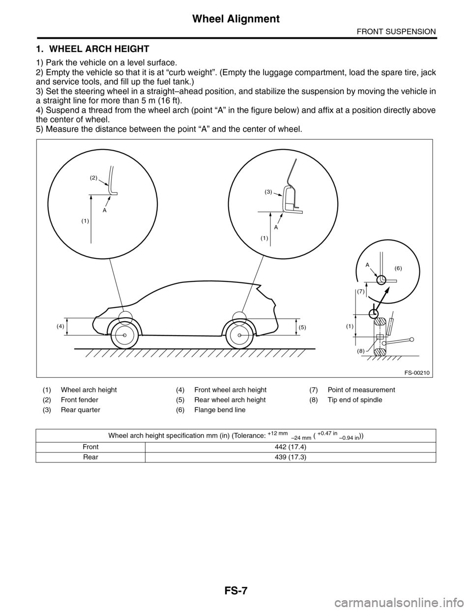
1. WHEEL ARCH HEIGHT
1) Park the vehicle on a level surface.
2) Empty the vehicle so that it is at “curb weight”. (Empty the luggage compartment, load the spare tire, jack
and service tools, and fill up the fuel tank.)
3) Set the steering wheel in a straight–ahead position, and stabilize the suspension by moving the vehicle in
a straight line for more than 5 m (16 ft).
4) Suspend a thread from the wheel arch (point “A” in the figure below) and affix at a position directly above
the center of wheel.
5) Measure the distance between the point “A” and the center of wheel.
(1) Wheel arch height (4) Front wheel arch height (7) Point of measurement
(2) Front fender (5) Rear wheel arch height (8) Tip end of spindle
(3) Rear quarter (6) Flange bend line
Wheel arch height specification mm (in) (Tolerance: +12 mm –24 mm ( +0.47 in –0.94 in))
Front 442 (17.4)
Rear 439 (17.3)
A
A
A
(4)
(1)
(2)
(3)
(1)
(5)(1)
(7)
(6)
(8)
FS-00210