2009 SUBARU TRIBECA height
[x] Cancel search: heightPage 856 of 2453

FS-8
Wheel Alignment
FRONT SUSPENSION
2. CAMBER
•INSPECTION
1) Place the front wheel on the turning radius
gauge. Make sure the ground contact surfaces of
front and rear wheels are at the same height.
2) Set the adapter at the center of wheel, and then
attach the wheel alignment gauge.
3) Measure the camber angle in accordance with
the operation manual for wheel alignment gauge.
•FRONT CAMBER ADJUSTMENT
1) When adjusting the camber, adjust it to the fol-
lowing value.
2) Loosen the two self–locking nuts located at the
lower front section of the strut.
NOTE:
When the adjusting bolt needs to be loosened or
tightened, hold its head with a wrench and turn the
self–locking nut.
3) Turn the camber adjusting bolt so that the cam-
ber is set at specification.
NOTE:
Moving the adjusting bolt by one scale changes the
camber by approximately 0°15′.
(1) Alignment gauge
(2) Turning radius gauge
(3) Adapter
Camber (Difference between RH and LH 45′ or less)
0°00′±0°45′
Camber (Difference between RH and LH 45′ or less)
0°00′±0°30′
FS-00213
(1)
(2)
(3)
(1) Strut
(2) Adjusting bolt
(3) Housing
(4) Outer
(5) Inner
(6) Camber is increased.
(7) Camber is decreased.
(1)
(4)
(6) (7)
(2)
(3)
(5)
FS-00196
Page 857 of 2453

FS-9
Wheel Alignment
FRONT SUSPENSION
4) Tighten two new self–locking nuts.
Tightening torque:
175 N·m (17.9 kgf-m, 129 ft-lb)
3. CASTER
•INSPECTION
1) Place the front wheel on the turning radius
gauge. Make sure the ground contact surfaces of
front and rear wheels are at the same height.
2) Set the adapter at the center of wheel, and then
attach the wheel alignment gauge.
3) Measure the caster angle in accordance with the
operation manual for wheel alignment gauge.
To i n c r e a s e c a m b e r :
Rotate the left side counterclockwise. Rotate the right side clockwise.
To d e c r e a s e c a m b e r :
Rotate the left side clockwise. Rotate the right side counterclockwise.
FS-00197FS-00198
FS-00198FS-00197
(1) Alignment gauge
(2) Turning radius gauge
(3) Adapter
FS-00213
(1)
(2)
(3)
Caster
4°04′(Reference)
Page 858 of 2453

FS-10
Wheel Alignment
FRONT SUSPENSION
4. STEERING ANGLE
•INSPECTION
•ADJUSTMENT
1) Turn the tie-rod to adjust the steering angle of
both inner and outer wheels.
2) Check the toe–in.
NOTE:
Correct the boot if it is twisted.
5. FRONT WHEEL TOE–IN
•INSPECTION
Toe-in:
0±3 mm (0±0.12 in)
1) Set the toe-in gauge in the position at wheel axis
center height behind the right and left front tires.
2) Place a mark at the center of both left and right
tires, and measure distance “A” between the
marks.
3) Move the vehicle forward to rotate the tires 180°.
NOTE:
Be sure to rotate the tires in the forward direction.
4) Measure distance “B” between the left and right
marks. Find toe–in using the following equation:
A – B = Toe–in
•ADJUSTMENT
When adjusting the toe-in, adjust it to the following
value.
Toe-in:
0±2 mm (0±0.08 in)
1) Check that the left and right wheel steering an-
gles are within specification.
2) Loosen the left and right side steering tie–rod
lock nuts.
3) Turn the left and right tie–rods by equal amounts
until the toe–in is at the specification.
Both the left and right tie–rods are right–hand
threaded. To increase toe–in, turn both tie–rods
clockwise by equal amount (viewing from the inside
of vehicle).
4) Tighten the tie–rod lock nut.
Tightening torque:
85 N·m (8.7 kgf-m, 62.7 ft-lb)
NOTE:
Check and correct the tie rod boot if twisted.
6. REAR WHEEL TOE–IN
•INSPECTION
Toe-in:
2±2 mm (0.08±0.08 in)
Refer to FRONT WHEEL TOE–IN for rear toe–in
inspection procedures.
Inner wheel Outer wheel
37.0°±1.5° 32.0°±1.5°
(1) Lock nut
FS-00014
(1)
FS-00015
AB
(1) Lock nut
FS-00014
(1)
Page 872 of 2453

FS-24
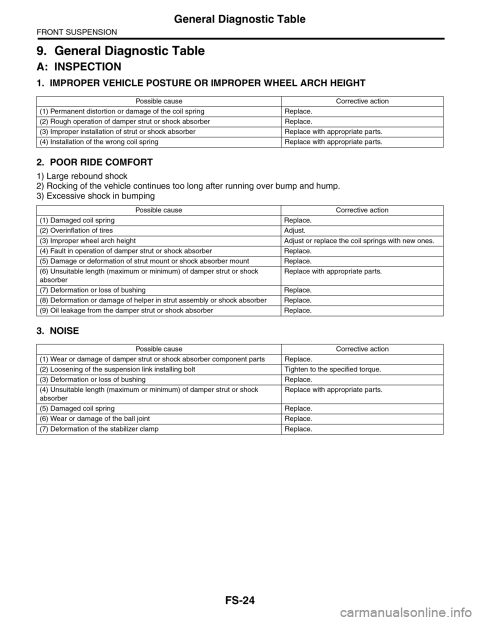
General Diagnostic Table
FRONT SUSPENSION
9. General Diagnostic Table
A: INSPECTION
1. IMPROPER VEHICLE POSTURE OR IMPROPER WHEEL ARCH HEIGHT
2. POOR RIDE COMFORT
1) Large rebound shock
2) Rocking of the vehicle continues too long after running over bump and hump.
3) Excessive shock in bumping
3. NOISE
Po ss ibl e c a us e C o r r e ct ive ac ti o n
(1) Permanent distortion or damage of the coil spring Replace.
(2) Rough operation of damper strut or shock absorber Replace.
(3) Improper installation of strut or shock absorber Replace with appropriate parts.
(4) Installation of the wrong coil spring Replace with appropriate parts.
Po ss ibl e ca us e C or r e ct i ve a ct io n
(1) Damaged coil spring Replace.
(2) Overinflation of tires Adjust.
(3) Improper wheel arch height Adjust or replace the coil springs with new ones.
(4) Fault in operation of damper strut or shock absorber Replace.
(5) Damage or deformation of strut mount or shock absorber mount Replace.
(6) Unsuitable length (maximum or minimum) of damper strut or shock
absorber
Replace with appropriate parts.
(7) Deformation or loss of bushing Replace.
(8) Deformation or damage of helper in strut assembly or shock absorber Replace.
(9) Oil leakage from the damper strut or shock absorber Replace.
Po ss ibl e c a us e C o r r e ct ive ac ti o n
(1) Wear or damage of damper strut or shock absorber component parts Replace.
(2) Loosening of the suspension link installing bolt Tighten to the specified torque.
(3) Deformation or loss of bushing Replace.
(4) Unsuitable length (maximum or minimum) of damper strut or shock
absorber
Replace with appropriate parts.
(5) Damaged coil spring Replace.
(6) Wear or damage of the ball joint Replace.
(7) Deformation of the stabilizer clamp Replace.
Page 929 of 2453

PS-49
General Diagnostic Table
POWER ASSISTED SYSTEM (POWER STEERING)
10.General Diagnostic Table
A: INSPECTION
*1 If the tires or wheels are wider than standard, the load to the power steering system is increased. Accordingly, in a condition,
for example before fluid warms-up, relief valve may work before reaching maximum turning angle. In this case, steering effort
may be heavy. When the measured hydraulic pressure is normal, there is no abnormal thing. *2 In cold weather, flow resistance will increase due to the cold hydraulic fluid, and steering effort will be heavier. After warming-up en-
gine, turn the steering wheel from stop to stop several times to warm-up fluid. If steering effort reduces normally, function is normal. *3 I n c o l d w e a t h e r o r w i t h i n s u f f i c i e n t w a r m – u p o f t h e e n g i n e , s t e e r i n g e f f o r t m a y b e h e a v y d u e t o e x c e s s i v e d r o p o f i d l e r p m w h en
turning the steering wheel. In this case, start the vehicle with increasing engine speed than usual. If steering effort reduces nor-
mally, function is normal.
Tr o u b l e P o s s i b l e c a u s e C o r r e c t i v e a c t i o n
•Steering effort is heavy in all
ranges.
•Steering effort is heavy at
stand still.
•Steering wheel vibrates
when turning.
1. Pulley belt
•Unequal length of pulley belts
•Contact with oil or grease
•Looseness or damage of the pulley belt
•Poor uniformity of the pulley belt cross section
•Pulley belt touches to pulley bottom
•Poor revolution of pulleys (except oil pump pulley)
•Poor revolution of oil pump pulley
Adjust or replace.
2. Tire and wheel
•Improper tire out of specifications*1
•Improper wheel out of specifications*1
•Tires not properly inflated
Replace or reinflate.
3. Fluid
•Low fluid level
•Air entry in fluid
•Entry of dust in the fluid
•Fluid deterioration
•Inadequate warm–up of fluid *2
Refill, bleed air,
replace or instruct cus-
tomer.
4. Idle speed
•Lower idle speed
•Excessive drop of idle speed at start or when turning the steering
wheel *3
Adjust or instruct cus-
tomer.
5. Measure the hydraulic pressure.
Replace the problem
parts.
6. Measure the steering wheel effort.
•Vehicle leads to one side or
the other.
•Returning force of steering
wheel to center is poor.
•Steering wheel vibrates
when turning.
1. Fluid line
•Folded hose
•Flattened pipe
Correct or replace.
2. Tire and wheel
•Flat tire
•Mixed use of different tires
•Mixed use of different wheels
•Abnormal wear of tire
•Unequal tread remaining
•Unequal pressure of tire
Adjust, fix or replace.
3. Front alignment
•Improper or unequal caster
•Improper or unequal toe–in
•Loose suspension connections
Adjust or retighten.
4. Others
•Damaged joint assembly
•Unbalanced height
•Unbalanced weight
Replace, adjust or
instruct customer.
5. Measure the steering wheel effort.
Page 935 of 2453

RS-2
General Description
REAR SUSPENSION
1. General Description
A: SPECIFICATION
NOTE:
•Front and rear toe–in and front camber can be
adjusted. Adjust if the toe–in or camber tolerance
exceeds specifications.
•Other items indicated in the specifications table
cannot be adjusted. If other items exceed specifica-
tions, check the suspension parts and connections
for deformation, and replace with new ones as re-
quired.
Wheel arch height
[Tolerance: +12 mm -24 mm ( +0.47 in -0.94 in)]mm (in) 439 (17.3)
Camber
[Tolerance: ±0°45′ Difference between RH and LH 45′ or less]–0°31′
To e – i n m m ( i n ) 2±2 (0.08±0.08) Toe angle (sum of both wheels): 0°9'±0°9'
Thrust angle [Tolerance: ±0°30′]0°
Diameter of stabilizer mm (in) 16 (0.63)
(1) Front
A – B = Positive: Toe-in, Negative: Toe–out
α = Individual toe angles
FS-00001
B
A
(1)
Page 950 of 2453

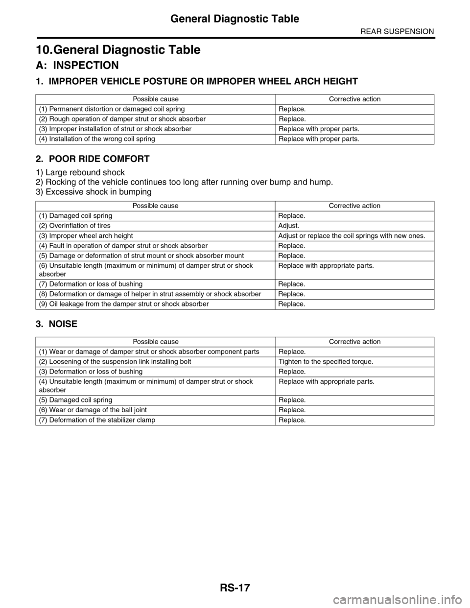
RS-17
General Diagnostic Table
REAR SUSPENSION
10.General Diagnostic Table
A: INSPECTION
1. IMPROPER VEHICLE POSTURE OR IMPROPER WHEEL ARCH HEIGHT
2. POOR RIDE COMFORT
1) Large rebound shock
2) Rocking of the vehicle continues too long after running over bump and hump.
3) Excessive shock in bumping
3. NOISE
Po ss ibl e c a us e C o r r e ct ive ac ti o n
(1) Permanent distortion or damaged coil spring Replace.
(2) Rough operation of damper strut or shock absorber Replace.
(3) Improper installation of strut or shock absorber Replace with proper parts.
(4) Installation of the wrong coil spring Replace with proper parts.
Po ss ibl e ca us e C or r e ct i ve a ct io n
(1) Damaged coil spring Replace.
(2) Overinflation of tires Adjust.
(3) Improper wheel arch height Adjust or replace the coil springs with new ones.
(4) Fault in operation of damper strut or shock absorber Replace.
(5) Damage or deformation of strut mount or shock absorber mount Replace.
(6) Unsuitable length (maximum or minimum) of damper strut or shock
absorber
Replace with appropriate parts.
(7) Deformation or loss of bushing Replace.
(8) Deformation or damage of helper in strut assembly or shock absorber Replace.
(9) Oil leakage from the damper strut or shock absorber Replace.
Po ss ibl e c a us e C o r r e ct ive ac ti o n
(1) Wear or damage of damper strut or shock absorber component parts Replace.
(2) Loosening of the suspension link installing bolt Tighten to the specified torque.
(3) Deformation or loss of bushing Replace.
(4) Unsuitable length (maximum or minimum) of damper strut or shock
absorber
Replace with appropriate parts.
(5) Damaged coil spring Replace.
(6) Wear or damage of the ball joint Replace.
(7) Deformation of the stabilizer clamp Replace.
Page 1121 of 2453

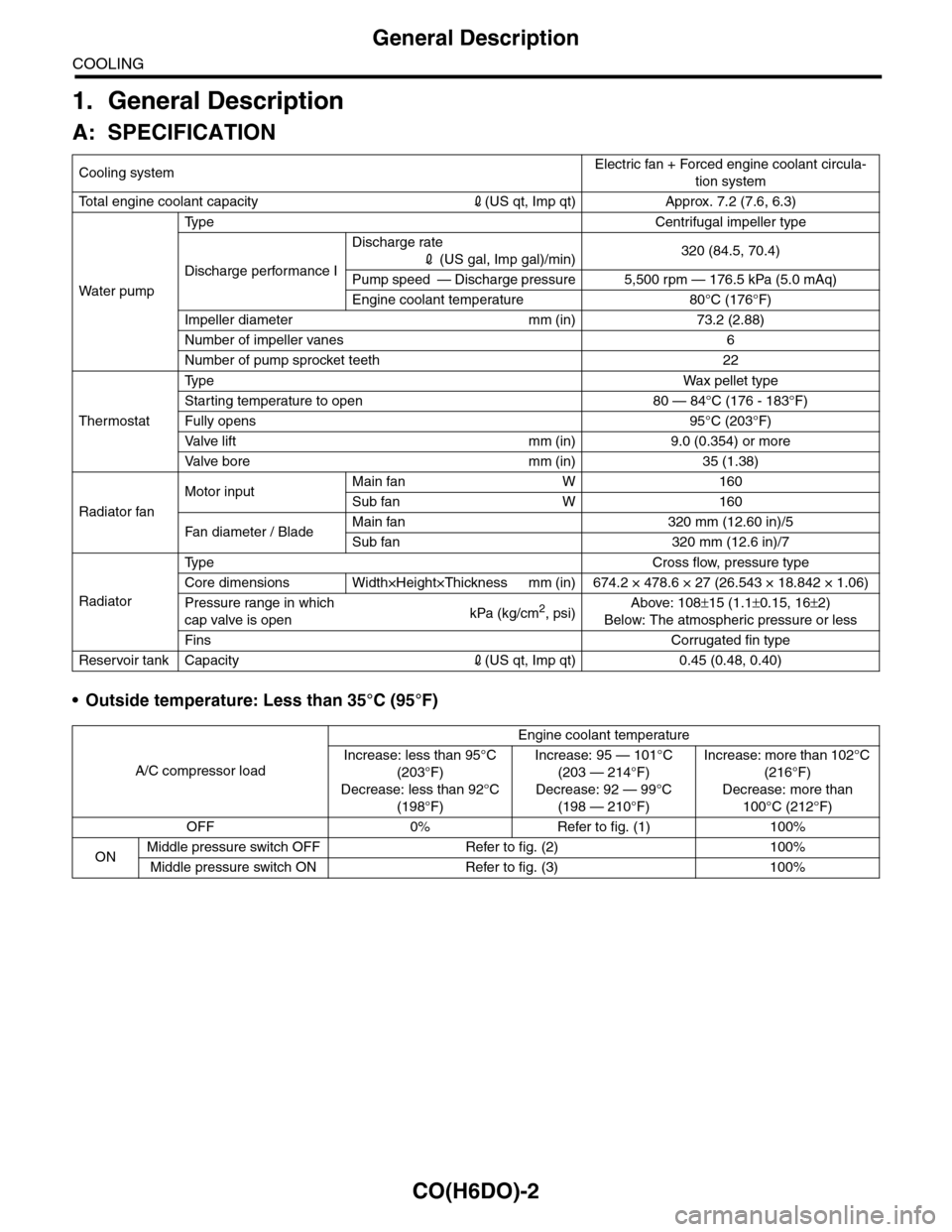
CO(H6DO)-2
General Description
COOLING
1. General Description
A: SPECIFICATION
•Outside temperature: Less than 35°C (95°F)
Cooling systemElectric fan + Forced engine coolant circula-
tion system
To t a l e n g i n e c o o l a n t c a p a c i t y2(US qt, Imp qt) Approx. 7.2 (7.6, 6.3)
Wa t er p u mp
Ty p e C e n t r i f u g a l i m p e l l e r t y p e
Discharge performance I
Discharge rate
2 (US gal, Imp gal)/min)320 (84.5, 70.4)
Pump speed — Discharge pressure 5,500 rpm — 176.5 kPa (5.0 mAq)
Engine coolant temperature 80°C (176°F)
Impeller diameter mm (in) 73.2 (2.88)
Number of impeller vanes 6
Number of pump sprocket teeth 22
Thermostat
Ty p eWa x p el l et t yp e
Starting temperature to open 80 — 84°C (176 - 183°F)
Fully opens 95°C (203°F)
Va l ve l i f t m m ( i n ) 9 . 0 ( 0 . 3 5 4 ) o r m o r e
Va l ve b o r e m m ( i n ) 3 5 ( 1 . 3 8 )
Radiator fan
Motor inputMain fan W 160
Sub fan W 160
Fan di a me t er / B la deMain fan 320 mm (12.60 in)/5
Sub fan 320 mm (12.6 in)/7
Radiator
Ty p e C r o s s f l o w , p r e s s u r e t y p e
Core dimensions Width×Height×Thickness mm (in) 674.2 × 478.6 × 27 (26.543 × 18.842 × 1.06)
Pressure range in which
cap valve is openkPa (kg/cm2, psi)Above: 108±15 (1.1±0.15, 16±2)
Below: The atmospheric pressure or less
FinsCorrugated fin type
Reservoir tank Capacity2(US qt, Imp qt) 0.45 (0.48, 0.40)
A/C compressor load
Engine coolant temperature
Increase: less than 95°C
(203°F)
Decrease: less than 92°C
(198°F)
Increase: 95 — 101°C
(203 — 214°F)
Decrease: 92 — 99°C
(198 — 210°F)
Increase: more than 102°C
(216°F)
Decrease: more than
100°C (212°F)
OFF 0% Refer to fig. (1) 100%
ONMiddle pressure switch OFF Refer to fig. (2) 100%
Middle pressure switch ON Refer to fig. (3) 100%