2009 SUBARU TRIBECA light
[x] Cancel search: lightPage 1453 of 2453
EN(H6DO)(diag)-292
Diagnostic Procedure with Diagnostic Trouble Code (DTC)
ENGINE (DIAGNOSTICS)
Step Check Yes No
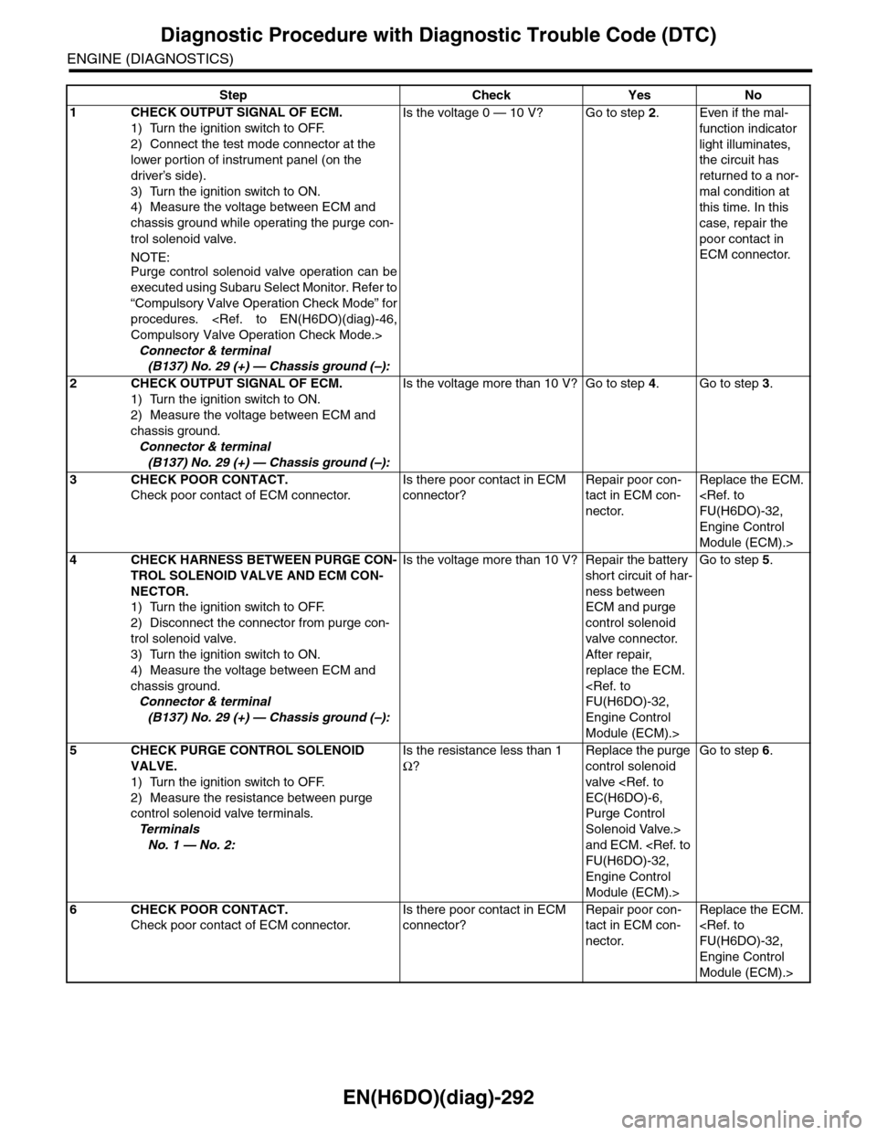
1CHECK OUTPUT SIGNAL OF ECM.
1) Turn the ignition switch to OFF.
2) Connect the test mode connector at the
lower portion of instrument panel (on the
driver’s side).
3) Turn the ignition switch to ON.
4) Measure the voltage between ECM and
chassis ground while operating the purge con-
trol solenoid valve.
NOTE:Purge control solenoid valve operation can be
executed using Subaru Select Monitor. Refer to
“Compulsory Valve Operation Check Mode” for
procedures.
Connector & terminal
(B137) No. 29 (+) — Chassis ground (–):
Is the voltage 0 — 10 V? Go to step 2.Even if the mal-
function indicator
light illuminates,
the circuit has
returned to a nor-
mal condition at
this time. In this
case, repair the
poor contact in
ECM connector.
2CHECK OUTPUT SIGNAL OF ECM.
1) Turn the ignition switch to ON.
2) Measure the voltage between ECM and
chassis ground.
Connector & terminal
(B137) No. 29 (+) — Chassis ground (–):
Is the voltage more than 10 V? Go to step 4.Go to step 3.
3CHECK POOR CONTACT.
Check poor contact of ECM connector.
Is there poor contact in ECM
connector?
Repair poor con-
tact in ECM con-
nector.
Replace the ECM.
Engine Control
Module (ECM).>
4CHECK HARNESS BETWEEN PURGE CON-
TROL SOLENOID VALVE AND ECM CON-
NECTOR.
1) Turn the ignition switch to OFF.
2) Disconnect the connector from purge con-
trol solenoid valve.
3) Turn the ignition switch to ON.
4) Measure the voltage between ECM and
chassis ground.
Connector & terminal
(B137) No. 29 (+) — Chassis ground (–):
Is the voltage more than 10 V? Repair the battery
short circuit of har-
ness between
ECM and purge
control solenoid
valve connector.
After repair,
replace the ECM.
Engine Control
Module (ECM).>
Go to step 5.
5CHECK PURGE CONTROL SOLENOID
VALVE.
1) Turn the ignition switch to OFF.
2) Measure the resistance between purge
control solenoid valve terminals.
Te r m i n a l s
No. 1 — No. 2:
Is the resistance less than 1
Ω?
Replace the purge
control solenoid
valve
Purge Control
Solenoid Valve.>
and ECM.
Engine Control
Module (ECM).>
Go to step 6.
6CHECK POOR CONTACT.
Check poor contact of ECM connector.
Is there poor contact in ECM
connector?
Repair poor con-
tact in ECM con-
nector.
Replace the ECM.
Engine Control
Module (ECM).>
Page 1622 of 2453
GD(H6DO)-10
Diagnostic Trouble Code (DTC) Detecting Criteria
GENERAL DESCRIPTION
4. GENERAL DRIVING CYCLE
1. Crankshaft Timing Diagnosis
Perform the diagnosis continuously after starting engine and while AVCS is not operating.
2. Slow Response Diagnosis
Perform the diagnosis continuously after warm-up, while AVCS is operating and the target timing advance is
small.
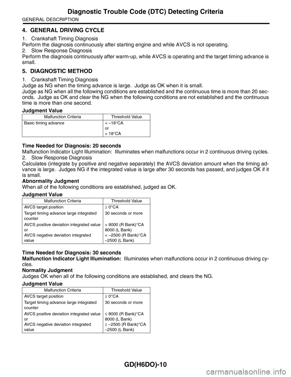
5. DIAGNOSTIC METHOD
1. Crankshaft Timing Diagnosis
Judge as NG when the timing advance is large. Judge as OK when it is small.
Judge as NG when all the following conditions are established and the continuous time is more than 20 sec-
onds. Judge as OK and clear the NG when the following conditions are not established and the continuous
time is more than one second.
Time Needed for Diagnosis: 20 seconds
Malfunction Indicator Light Illumination: Illuminates when malfunctions occur in 2 continuous driving cycles.
2. Slow Response Diagnosis
Calculates (integrate by positive and negative separately) the AVCS deviation amount when the timing ad-
vance is large. Judges NG if the integrated value is large after 30 seconds has passed, and judges OK if it
is small.
Abnormality Judgment
When all of the following conditions are established, judged as OK.
Time Needed for Diagnosis: 30 seconds
Malfunction Indicator Light Illumination: Illuminates when malfunctions occur in 2 continuous driving cy-
cles.
Normality Judgment
Judges OK when all of the following conditions are established, and clears the NG.
Judgment Value
Malfunction Criteria Threshold Value
Basic timing advance < –18°CA
or
> 18°CA
Judgment Value
Malfunction Criteria Threshold Value
AV C S t a r g e t p o s i t i o n≥ 0°CA
Ta r g e t t i m i n g a d v a n c e l a r g e i n t e g r a t e d
counter
30 seconds or more
AV C S p o s i t i v e d ev i a t i o n i n t e g r a t e d va l u e
or
AV C S n e g a t i v e d ev i a t i o n i n t e g r a t e d
value
> 8000 (R Bank)°CA
8000 (L Bank)
< –2500 (R Bank)°CA
–2500 (L Bank)
Judgment Value
Malfunction Criteria Threshold Value
AV C S t a r g e t p o s i t i o n≥ 0°CA
Ta r g e t t i m i n g a d v a n c e l a r g e i n t e g r a t e d
counter
30 seconds or more
AV C S p o s i t i v e d ev i a t i o n i n t e g r a t e d va l u e
or
AV C S n e g a t i v e d ev i a t i o n i n t e g r a t e d
value
≤ 8000 (R Bank)°CA
8000 (L Bank)
≥ –2500 (R Bank)°CA
–2500 (L Bank)
Page 1623 of 2453
GD(H6DO)-11
Diagnostic Trouble Code (DTC) Detecting Criteria
GENERAL DESCRIPTION
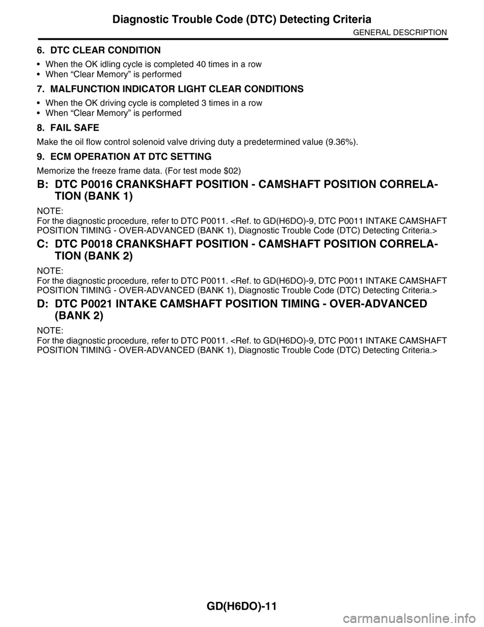
6. DTC CLEAR CONDITION
•When the OK idling cycle is completed 40 times in a row
•When “Clear Memory” is performed
7. MALFUNCTION INDICATOR LIGHT CLEAR CONDITIONS
•When the OK driving cycle is completed 3 times in a row
•When “Clear Memory” is performed
8. FAIL SAFE
Make the oil flow control solenoid valve driving duty a predetermined value (9.36%).
9. ECM OPERATION AT DTC SETTING
Memorize the freeze frame data. (For test mode $02)
B: DTC P0016 CRANKSHAFT POSITION - CAMSHAFT POSITION CORRELA-
TION (BANK 1)
NOTE:
For the diagnostic procedure, refer to DTC P0011.
C: DTC P0018 CRANKSHAFT POSITION - CAMSHAFT POSITION CORRELA-
TION (BANK 2)
NOTE:
For the diagnostic procedure, refer to DTC P0011.
D: DTC P0021 INTAKE CAMSHAFT POSITION TIMING - OVER-ADVANCED
(BANK 2)
NOTE:
For the diagnostic procedure, refer to DTC P0011.
Page 1626 of 2453
GD(H6DO)-14
Diagnostic Trouble Code (DTC) Detecting Criteria
GENERAL DESCRIPTION
4. GENERAL DRIVING CYCLE
Perform the diagnosis continuously 6 seconds after engine start while variable valve lift is being controlled.
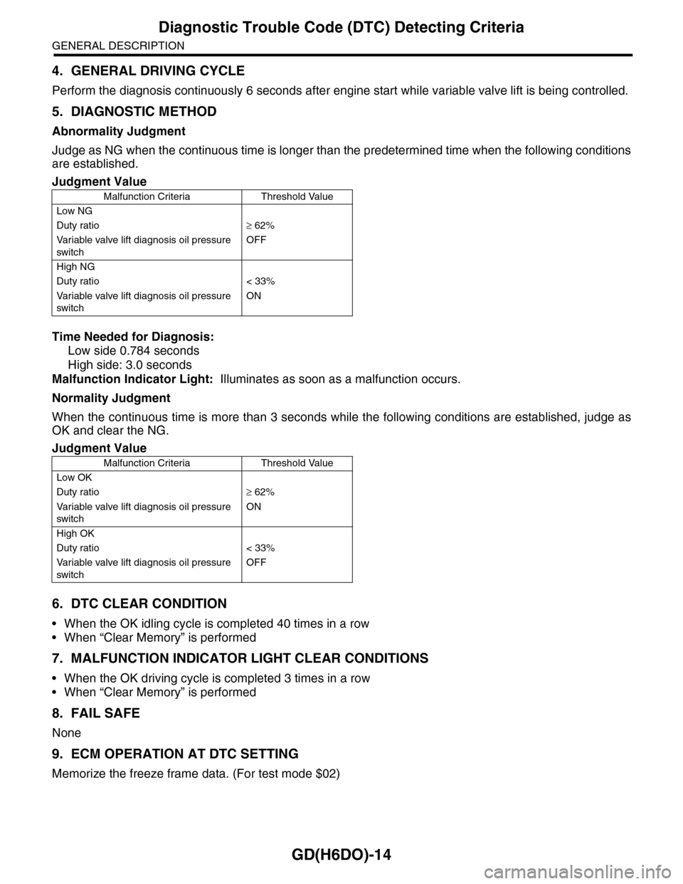
5. DIAGNOSTIC METHOD
Abnormality Judgment
Judge as NG when the continuous time is longer than the predetermined time when the following conditions
are established.
Time Needed for Diagnosis:
Low side 0.784 seconds
High side: 3.0 seconds
Malfunction Indicator Light: Illuminates as soon as a malfunction occurs.
Normality Judgment
When the continuous time is more than 3 seconds while the following conditions are established, judge as
OK and clear the NG.
6. DTC CLEAR CONDITION
•When the OK idling cycle is completed 40 times in a row
•When “Clear Memory” is performed
7. MALFUNCTION INDICATOR LIGHT CLEAR CONDITIONS
•When the OK driving cycle is completed 3 times in a row
•When “Clear Memory” is performed
8. FAIL SAFE
None
9. ECM OPERATION AT DTC SETTING
Memorize the freeze frame data. (For test mode $02)
Judgment Value
Malfunction Criteria Threshold Value
Low NG
Duty ratio≥ 62%
Va r i a b l e va l v e l i f t d i a g n o s i s o i l p r e s s u r e
switch
OFF
High NG
Duty ratio < 33%
Va r i a b l e va l v e l i f t d i a g n o s i s o i l p r e s s u r e
switch
ON
Judgment Value
Malfunction Criteria Threshold Value
Low OK
Duty ratio≥ 62%
Va r i a b l e va l v e l i f t d i a g n o s i s o i l p r e s s u r e
switch
ON
High OK
Duty ratio < 33%
Va r i a b l e va l v e l i f t d i a g n o s i s o i l p r e s s u r e
switch
OFF
Page 1628 of 2453
GD(H6DO)-16
Diagnostic Trouble Code (DTC) Detecting Criteria
GENERAL DESCRIPTION
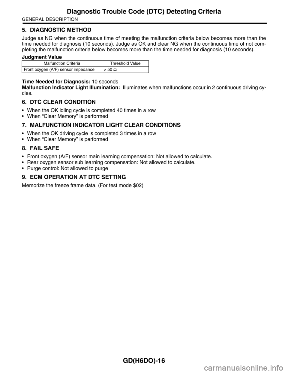
5. DIAGNOSTIC METHOD
Judge as NG when the continuous time of meeting the malfunction criteria below becomes more than the
time needed for diagnosis (10 seconds). Judge as OK and clear NG when the continuous time of not com-
pleting the malfunction criteria below becomes more than the time needed for diagnosis (10 seconds).
Time Needed for Diagnosis: 10 seconds
Malfunction Indicator Light Illumination: Illuminates when malfunctions occur in 2 continuous driving cy-
cles.
6. DTC CLEAR CONDITION
•When the OK idling cycle is completed 40 times in a row
•When “Clear Memory” is performed
7. MALFUNCTION INDICATOR LIGHT CLEAR CONDITIONS
•When the OK driving cycle is completed 3 times in a row
•When “Clear Memory” is performed
8. FAIL SAFE
•Front oxygen (A/F) sensor main learning compensation: Not allowed to calculate.
•Rear oxygen sensor sub learning compensation: Not allowed to calculate.
•Purge control: Not allowed to purge
9. ECM OPERATION AT DTC SETTING
Memorize the freeze frame data. (For test mode $02)
Judgment Value
Malfunction Criteria Threshold Value
Fr o nt ox yg e n ( A / F) s en so r im pe d an c e > 5 0 Ω
Page 1629 of 2453
GD(H6DO)-17
Diagnostic Trouble Code (DTC) Detecting Criteria
GENERAL DESCRIPTION
H: DTC P0031 HO2S HEATER CONTROL CIRCUIT LOW (BANK 1 SENSOR 1)
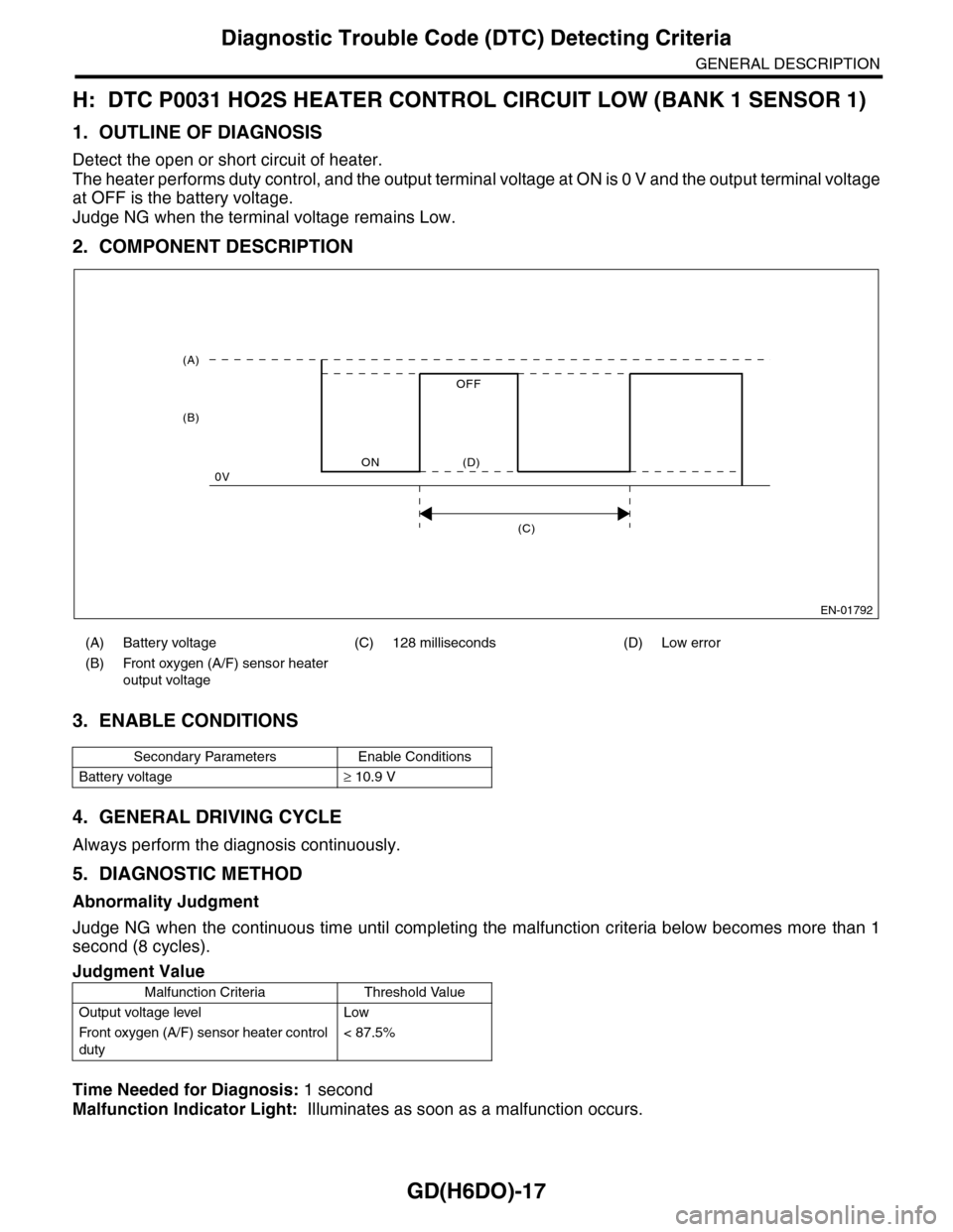
1. OUTLINE OF DIAGNOSIS
Detect the open or short circuit of heater.
The heater performs duty control, and the output terminal voltage at ON is 0 V and the output terminal voltage
at OFF is the battery voltage.
Judge NG when the terminal voltage remains Low.
2. COMPONENT DESCRIPTION
3. ENABLE CONDITIONS
4. GENERAL DRIVING CYCLE
Always perform the diagnosis continuously.
5. DIAGNOSTIC METHOD
Abnormality Judgment
Judge NG when the continuous time until completing the malfunction criteria below becomes more than 1
second (8 cycles).
Time Needed for Diagnosis: 1 second
Malfunction Indicator Light: Illuminates as soon as a malfunction occurs.
(A) Battery voltage (C) 128 milliseconds (D) Low error
(B) Front oxygen (A/F) sensor heater
output voltage
Secondary Parameters Enable Conditions
Battery voltage≥ 10.9 V
Judgment Value
Malfunction Criteria Threshold Value
Output voltage level Low
Fr o nt ox yg en (A / F ) se ns or h ea t er co n tr o l
duty
< 87.5%
EN-01792
(C)
(A)
(B)
ON
OFF
0V(D)
Page 1630 of 2453
GD(H6DO)-18
Diagnostic Trouble Code (DTC) Detecting Criteria
GENERAL DESCRIPTION
Normality Judgment
Judge as OK and clear the NG when the malfunction criteria below are completed.
6. DTC CLEAR CONDITION
•When the OK idling cycle is completed 40 times in a row
•When “Clear Memory” is performed
7. MALFUNCTION INDICATOR LIGHT CLEAR CONDITIONS
•When the OK driving cycle is completed 3 times in a row
•When “Clear Memory” is performed
8. FAIL SAFE
•A/F main learning: Not allowed to calculate the A/F main learning compensation factor.
•Purge control: Not allowed to purge
9. ECM OPERATION AT DTC SETTING
Memorize the freeze frame data. (For test mode $02)
Judgment Value
Malfunction Criteria Threshold Value
Output voltage level High
Page 1631 of 2453
GD(H6DO)-19
Diagnostic Trouble Code (DTC) Detecting Criteria
GENERAL DESCRIPTION
I: DTC P0032 HO2S HEATER CONTROL CIRCUIT HIGH (BANK 1 SENSOR 1)
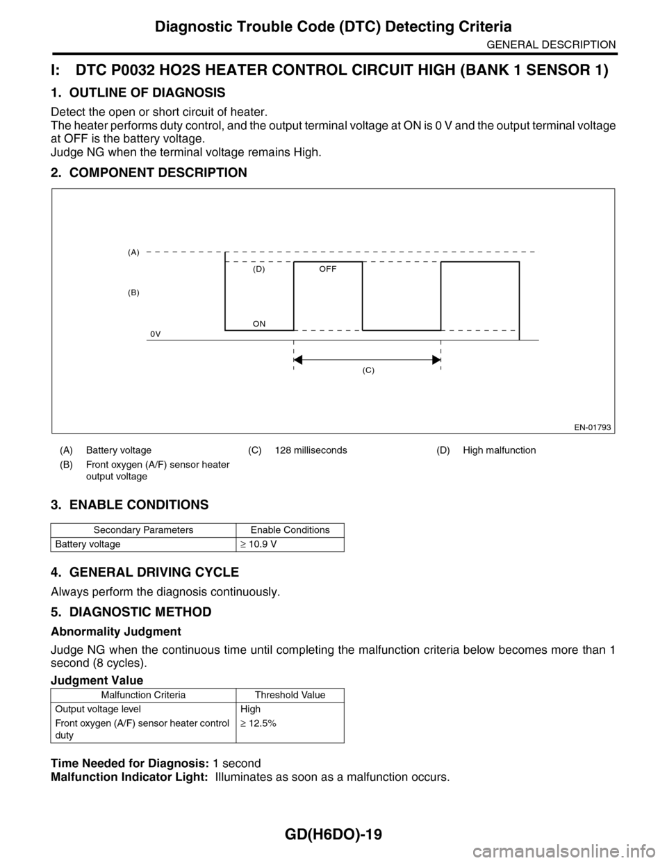
1. OUTLINE OF DIAGNOSIS
Detect the open or short circuit of heater.
The heater performs duty control, and the output terminal voltage at ON is 0 V and the output terminal voltage
at OFF is the battery voltage.
Judge NG when the terminal voltage remains High.
2. COMPONENT DESCRIPTION
3. ENABLE CONDITIONS
4. GENERAL DRIVING CYCLE
Always perform the diagnosis continuously.
5. DIAGNOSTIC METHOD
Abnormality Judgment
Judge NG when the continuous time until completing the malfunction criteria below becomes more than 1
second (8 cycles).
Time Needed for Diagnosis: 1 second
Malfunction Indicator Light: Illuminates as soon as a malfunction occurs.
(A) Battery voltage (C) 128 milliseconds (D) High malfunction
(B) Front oxygen (A/F) sensor heater
output voltage
Secondary Parameters Enable Conditions
Battery voltage≥ 10.9 V
Judgment Value
Malfunction Criteria Threshold Value
Output voltage level High
Fr o nt ox yg en (A / F ) se ns or h ea t er co n tr o l
duty
≥ 12.5%
EN-01793
(C)
(A)
(B)
ON
OFF
0V
(D)