2009 SUBARU TRIBECA light
[x] Cancel search: lightPage 1213 of 2453
EN(H6DO)(diag)-52
Malfunction Indicator Light
ENGINE (DIAGNOSTICS)
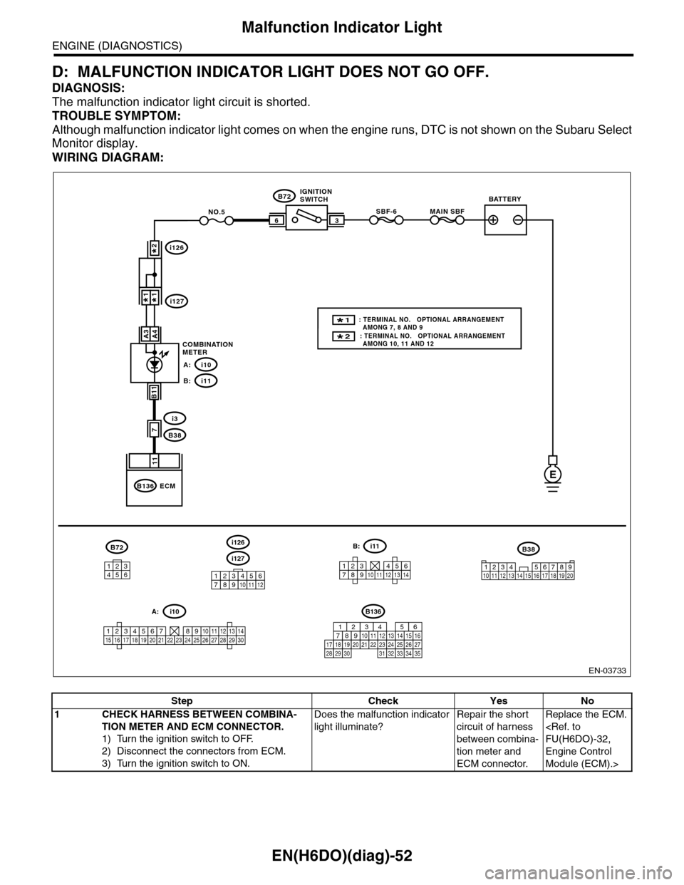
D: MALFUNCTION INDICATOR LIGHT DOES NOT GO OFF.
DIAGNOSIS:
The malfunction indicator light circuit is shorted.
TROUBLE SYMPTOM:
Although malfunction indicator light comes on when the engine runs, DTC is not shown on the Subaru Select
Monitor display.
WIRING DIAGRAM:
EN-03733
3
B72
i3
B38
B136
SBF-66
11
A4
7
MAIN SBFNO.5
B11
E
A3
B72
134562
B38
1234 5678910 11 12 13 14 15 16 17 18 19 20
ECM
COMBINATIONMETER
IGNITIONSWITCHBATTERY
i126
i1271*1*
2*
i10A:
i11B:
i127
i126
123456789101112
1234567891011121314
i11B:
123456789101112131415161718192021222324252627282930
i10A:
2* : TERMINAL NO. OPTIONAL ARRANGEMENT AMONG 10, 11 AND 12
1* : TERMINAL NO. OPTIONAL ARRANGEMENT AMONG 7, 8 AND 9
B136
16101112131415252430
9871718192028212223293231
123456
2726333435
Step Check Yes No
1CHECK HARNESS BETWEEN COMBINA-
TION METER AND ECM CONNECTOR.
1) Turn the ignition switch to OFF.
2) Disconnect the connectors from ECM.
3) Turn the ignition switch to ON.
Does the malfunction indicator
light illuminate?
Repair the short
circuit of harness
between combina-
tion meter and
ECM connector.
Replace the ECM.
Engine Control
Module (ECM).>
Page 1214 of 2453
EN(H6DO)(diag)-53
Malfunction Indicator Light
ENGINE (DIAGNOSTICS)
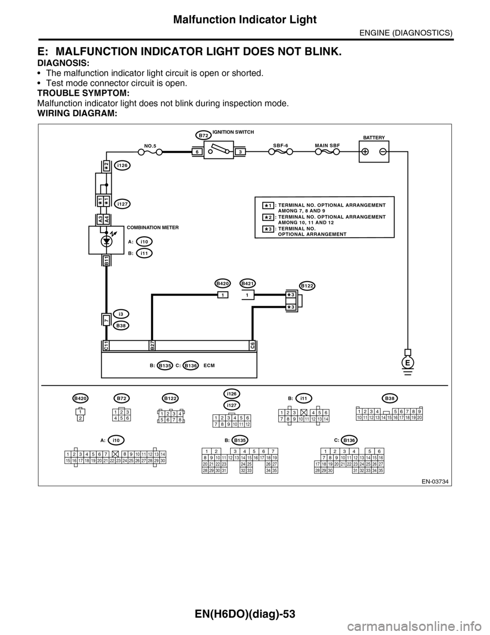
E: MALFUNCTION INDICATOR LIGHT DOES NOT BLINK.
DIAGNOSIS:
•The malfunction indicator light circuit is open or shorted.
•Test mode connector circuit is open.
TROUBLE SYMPTOM:
Malfunction indicator light does not blink during inspection mode.
WIRING DIAGRAM:
EN-03734
i126
i1271*1*
2*
i10A:
i11B:
BATTERY
3
B72
B420B421
IGNITION SWITCH
COMBINATION METER
B135B:
SBF-66
C11B27C6
ECM
B72
7
MAIN SBFNO.5
11
B420
1212
B11
i3
B38
E
A4A3
B136C:
134562
B38
1234 5678910 11 12 13 14 15 16 17 18 19 2012345678
B122
3*: TERMINAL NO. OPTIONAL ARRANGEMENT
2*: TERMINAL NO. OPTIONAL ARRANGEMENT AMONG 10, 11 AND 12
1*: TERMINAL NO. OPTIONAL ARRANGEMENT AMONG 7, 8 AND 9
B122
3*
3*
i127
i126
123456789101112
1234567891011121314
i11B:
123456789101112131415161718192021222324252627282930
i10A:B135
5672134
29
101112131415252416
30
98171819202821222332312627333435
B:B136
16101112131415252430
9871718192028212223293231
123456
2726333435
C:
Page 1215 of 2453
EN(H6DO)(diag)-54
Malfunction Indicator Light
ENGINE (DIAGNOSTICS)
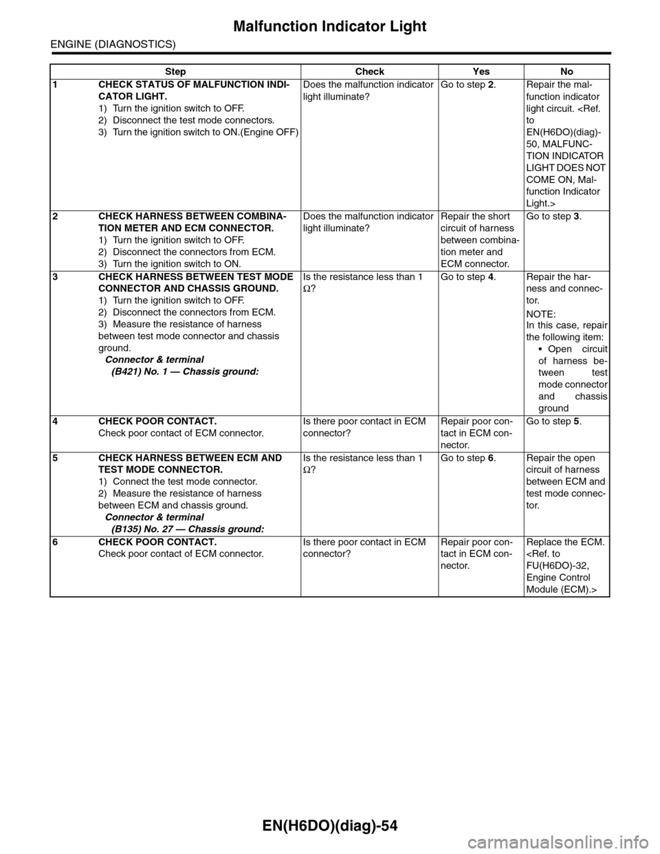
Step Check Yes No
1CHECK STATUS OF MALFUNCTION INDI-
CATOR LIGHT.
1) Turn the ignition switch to OFF.
2) Disconnect the test mode connectors.
3) Turn the ignition switch to ON.(Engine OFF)
Does the malfunction indicator
light illuminate?
Go to step 2.Repair the mal-
function indicator
light circuit.
EN(H6DO)(diag)-
50, MALFUNC-
TION INDICATOR
LIGHT DOES NOT
COME ON, Mal-
function Indicator
Light.>
2CHECK HARNESS BETWEEN COMBINA-
TION METER AND ECM CONNECTOR.
1) Turn the ignition switch to OFF.
2) Disconnect the connectors from ECM.
3) Turn the ignition switch to ON.
Does the malfunction indicator
light illuminate?
Repair the short
circuit of harness
between combina-
tion meter and
ECM connector.
Go to step 3.
3CHECK HARNESS BETWEEN TEST MODE
CONNECTOR AND CHASSIS GROUND.
1) Turn the ignition switch to OFF.
2) Disconnect the connectors from ECM.
3) Measure the resistance of harness
between test mode connector and chassis
ground.
Connector & terminal
(B421) No. 1 — Chassis ground:
Is the resistance less than 1
Ω?
Go to step 4.Repair the har-
ness and connec-
tor.
NOTE:
In this case, repair
the following item:
•Open circuit
of harness be-
tween test
mode connector
and chassis
ground
4CHECK POOR CONTACT.
Check poor contact of ECM connector.
Is there poor contact in ECM
connector?
Repair poor con-
tact in ECM con-
nector.
Go to step 5.
5CHECK HARNESS BETWEEN ECM AND
TEST MODE CONNECTOR.
1) Connect the test mode connector.
2) Measure the resistance of harness
between ECM and chassis ground.
Connector & terminal
(B135) No. 27 — Chassis ground:
Is the resistance less than 1
Ω?
Go to step 6.Repair the open
circuit of harness
between ECM and
test mode connec-
tor.
6CHECK POOR CONTACT.
Check poor contact of ECM connector.
Is there poor contact in ECM
connector?
Repair poor con-
tact in ECM con-
nector.
Replace the ECM.
Engine Control
Module (ECM).>
Page 1216 of 2453
EN(H6DO)(diag)-55
Malfunction Indicator Light
ENGINE (DIAGNOSTICS)
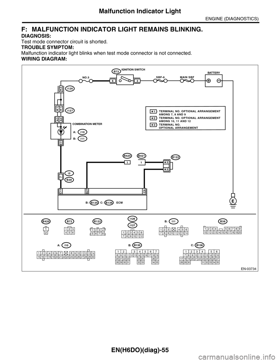
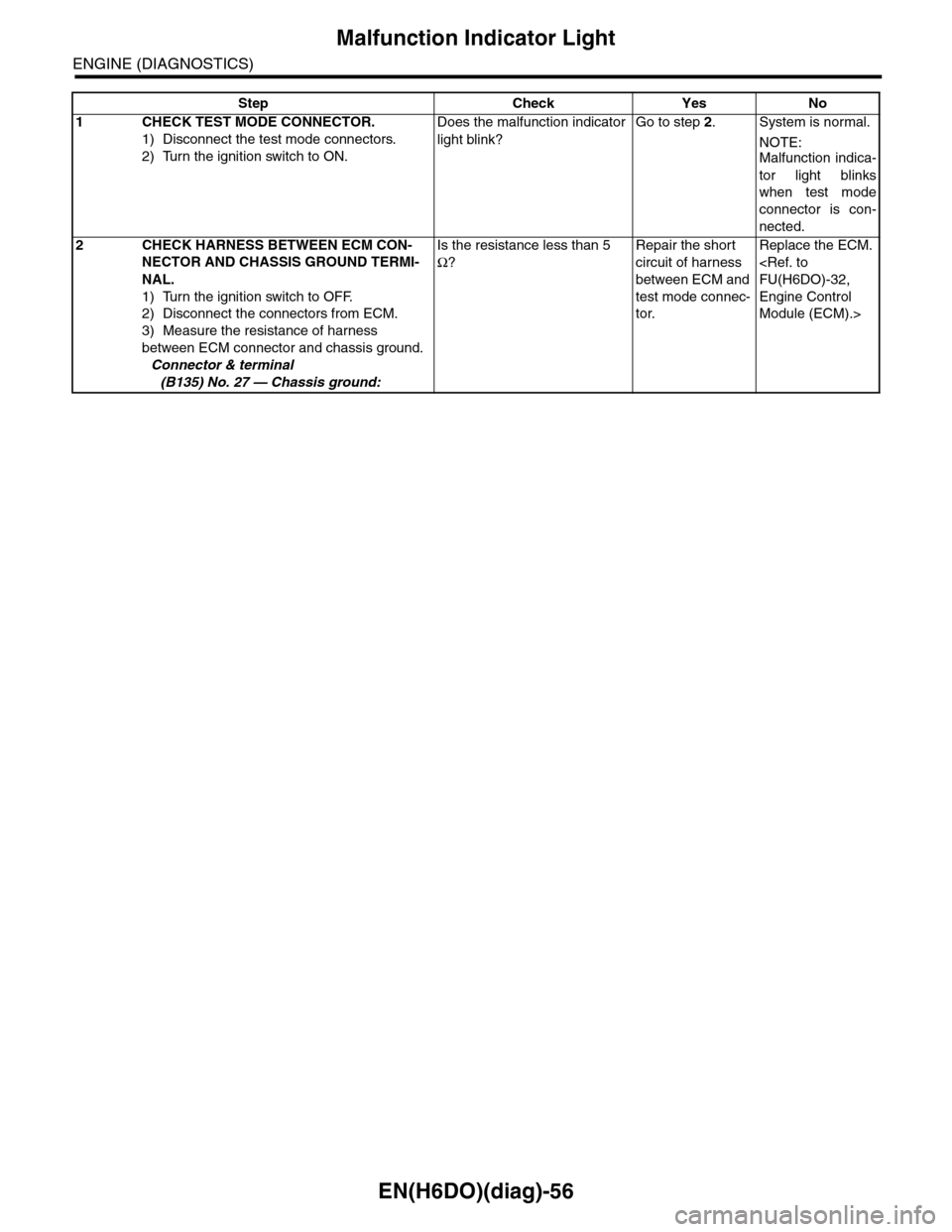
F: MALFUNCTION INDICATOR LIGHT REMAINS BLINKING.
DIAGNOSIS:
Test mode connector circuit is shorted.
TROUBLE SYMPTOM:
Malfunction indicator light blinks when test mode connector is not connected.
WIRING DIAGRAM:
EN-03734
i126
i1271*1*
2*
i10A:
i11B:
BATTERY
3
B72
B420B421
IGNITION SWITCH
COMBINATION METER
B135B:
SBF-66
C11B27C6
ECM
B72
7
MAIN SBFNO.5
11
B420
1212
B11
i3
B38
E
A4A3
B136C:
134562
B38
1234 5678910 11 12 13 14 15 16 17 18 19 2012345678
B122
3*: TERMINAL NO. OPTIONAL ARRANGEMENT
2*: TERMINAL NO. OPTIONAL ARRANGEMENT AMONG 10, 11 AND 12
1*: TERMINAL NO. OPTIONAL ARRANGEMENT AMONG 7, 8 AND 9
B122
3*
3*
i127
i126
123456789101112
1234567891011121314
i11B:
123456789101112131415161718192021222324252627282930
i10A:B135
5672134
29
101112131415252416
30
98171819202821222332312627333435
B:B136
16101112131415252430
9871718192028212223293231
123456
2726333435
C:
Page 1217 of 2453
EN(H6DO)(diag)-56
Malfunction Indicator Light
ENGINE (DIAGNOSTICS)
Step Check Yes No
1CHECK TEST MODE CONNECTOR.
1) Disconnect the test mode connectors.
2) Turn the ignition switch to ON.
Does the malfunction indicator
light blink?
Go to step 2.System is normal.
NOTE:Malfunction indica-
tor light blinks
when test mode
connector is con-
nected.
2CHECK HARNESS BETWEEN ECM CON-
NECTOR AND CHASSIS GROUND TERMI-
NAL.
1) Turn the ignition switch to OFF.
2) Disconnect the connectors from ECM.
3) Measure the resistance of harness
between ECM connector and chassis ground.
Connector & terminal
(B135) No. 27 — Chassis ground:
Is the resistance less than 5
Ω?
Repair the short
circuit of harness
between ECM and
test mode connec-
tor.
Replace the ECM.
Engine Control
Module (ECM).>
Page 1293 of 2453
EN(H6DO)(diag)-132
Diagnostic Procedure with Diagnostic Trouble Code (DTC)
ENGINE (DIAGNOSTICS)
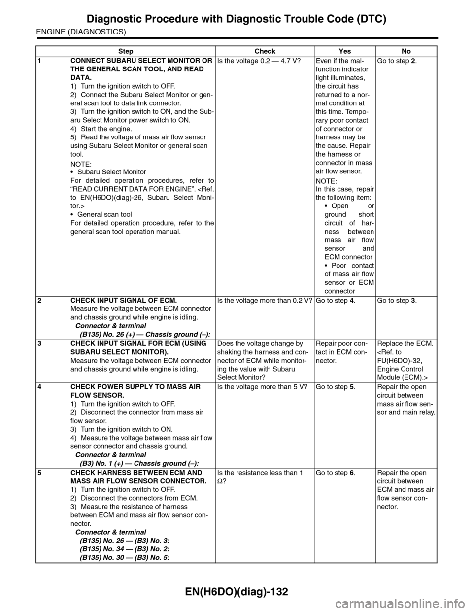
Step Check Yes No
1CONNECT SUBARU SELECT MONITOR OR
THE GENERAL SCAN TOOL, AND READ
DATA.
1) Turn the ignition switch to OFF.
2) Connect the Subaru Select Monitor or gen-
eral scan tool to data link connector.
3) Turn the ignition switch to ON, and the Sub-
aru Select Monitor power switch to ON.
4) Start the engine.
5) Read the voltage of mass air flow sensor
using Subaru Select Monitor or general scan
tool.
NOTE:•Subaru Select Monitor
For detailed operation procedures, refer to
“READ CURRENT DATA FOR ENGINE”.
tor.>
•General scan tool
For detailed operation procedure, refer to the
general scan tool operation manual.
Is the voltage 0.2 — 4.7 V? Even if the mal-
function indicator
light illuminates,
the circuit has
returned to a nor-
mal condition at
this time. Tempo-
rary poor contact
of connector or
harness may be
the cause. Repair
the harness or
connector in mass
air flow sensor.
NOTE:
In this case, repair
the following item:
•Open or
ground short
circuit of har-
ness between
mass air flow
sensor and
ECM connector
•Poor contact
of mass air flow
sensor or ECM
connector
Go to step 2.
2CHECK INPUT SIGNAL OF ECM.
Measure the voltage between ECM connector
and chassis ground while engine is idling.
Connector & terminal
(B135) No. 26 (+) — Chassis ground (–):
Is the voltage more than 0.2 V? Go to step 4.Go to step 3.
3CHECK INPUT SIGNAL FOR ECM (USING
SUBARU SELECT MONITOR).
Measure the voltage between ECM connector
and chassis ground while engine is idling.
Does the voltage change by
shaking the harness and con-
nector of ECM while monitor-
ing the value with Subaru
Select Monitor?
Repair poor con-
tact in ECM con-
nector.
Replace the ECM.
Engine Control
Module (ECM).>
4CHECK POWER SUPPLY TO MASS AIR
FLOW SENSOR.
1) Turn the ignition switch to OFF.
2) Disconnect the connector from mass air
flow sensor.
3) Turn the ignition switch to ON.
4) Measure the voltage between mass air flow
sensor connector and chassis ground.
Connector & terminal
(B3) No. 1 (+) — Chassis ground (–):
Is the voltage more than 5 V? Go to step 5.Repair the open
circuit between
mass air flow sen-
sor and main relay.
5CHECK HARNESS BETWEEN ECM AND
MASS AIR FLOW SENSOR CONNECTOR.
1) Turn the ignition switch to OFF.
2) Disconnect the connectors from ECM.
3) Measure the resistance of harness
between ECM and mass air flow sensor con-
nector.
Connector & terminal
(B135) No. 26 — (B3) No. 3:
(B135) No. 34 — (B3) No. 2:
(B135) No. 30 — (B3) No. 5:
Is the resistance less than 1
Ω?
Go to step 6.Repair the open
circuit between
ECM and mass air
flow sensor con-
nector.
Page 1296 of 2453
EN(H6DO)(diag)-135
Diagnostic Procedure with Diagnostic Trouble Code (DTC)
ENGINE (DIAGNOSTICS)
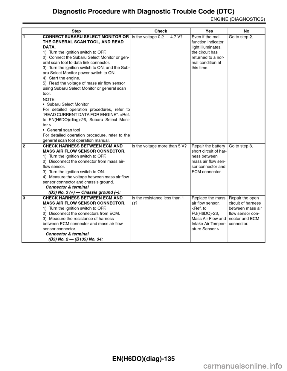
Step Check Yes No
1CONNECT SUBARU SELECT MONITOR OR
THE GENERAL SCAN TOOL, AND READ
DATA.
1) Turn the ignition switch to OFF.
2) Connect the Subaru Select Monitor or gen-
eral scan tool to data link connector.
3) Turn the ignition switch to ON, and the Sub-
aru Select Monitor power switch to ON.
4) Start the engine.
5) Read the voltage of mass air flow sensor
using Subaru Select Monitor or general scan
tool.
NOTE:•Subaru Select Monitor
For detailed operation procedures, refer to
“READ CURRENT DATA FOR ENGINE”.
tor.>
•General scan tool
For detailed operation procedure, refer to the
general scan tool operation manual.
Is the voltage 0.2 — 4.7 V? Even if the mal-
function indicator
light illuminates,
the circuit has
returned to a nor-
mal condition at
this time.
Go to step 2.
2CHECK HARNESS BETWEEN ECM AND
MASS AIR FLOW SENSOR CONNECTOR.
1) Turn the ignition switch to OFF.
2) Disconnect the connector from mass air-
flow sensor.
3) Turn the ignition switch to ON.
4) Measure the voltage between mass air flow
sensor connector and chassis ground.
Connector & terminal
(B3) No. 3 (+) — Chassis ground (–):
Is the voltage more than 5 V? Repair the battery
short circuit of har-
ness between
mass air flow sen-
sor connector and
ECM connector.
Go to step 3.
3CHECK HARNESS BETWEEN ECM AND
MASS AIR FLOW SENSOR CONNECTOR.
1) Turn the ignition switch to OFF.
2) Disconnect the connectors from ECM.
3) Measure the resistance of harness
between ECM connector and mass air flow
sensor connector.
Connector & terminal
(B3) No. 2 — (B135) No. 34:
Is the resistance less than 1
Ω?
Replace the mass
air flow sensor.
Mass Air Flow and
Intake Air Temper-
ature Sensor.>
Repair the open
circuit of harness
between mass air
flow sensor con-
nector and ECM
connector.
Page 1298 of 2453
EN(H6DO)(diag)-137
Diagnostic Procedure with Diagnostic Trouble Code (DTC)
ENGINE (DIAGNOSTICS)
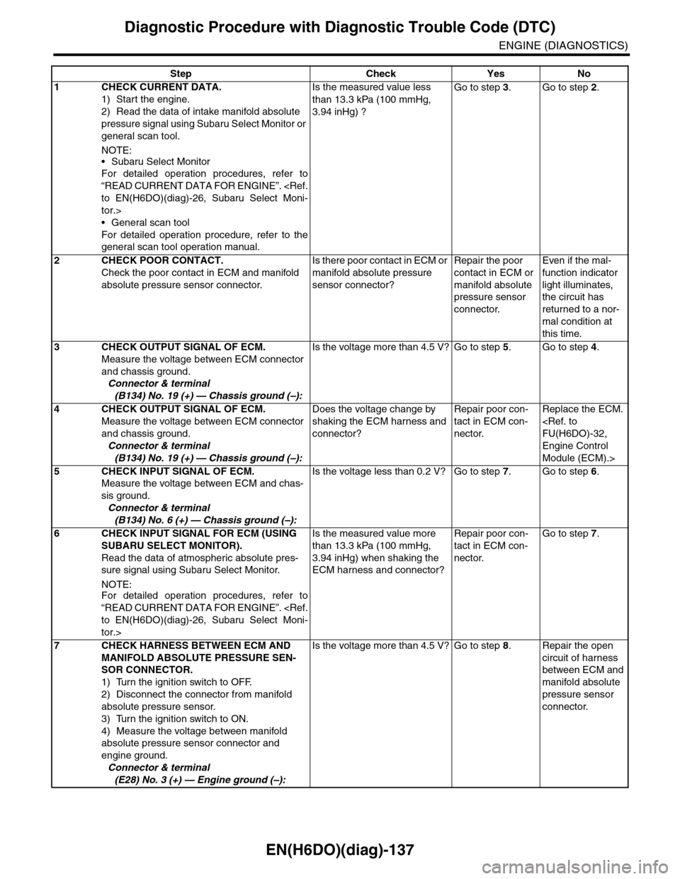
Step Check Yes No
1CHECK CURRENT DATA.
1) Start the engine.
2) Read the data of intake manifold absolute
pressure signal using Subaru Select Monitor or
general scan tool.
NOTE:
•Subaru Select Monitor
For detailed operation procedures, refer to
“READ CURRENT DATA FOR ENGINE”.
tor.>
•General scan tool
For detailed operation procedure, refer to the
general scan tool operation manual.
Is the measured value less
than 13.3 kPa (100 mmHg,
3.94 inHg) ?
Go to step 3.Go to step 2.
2CHECK POOR CONTACT.
Check the poor contact in ECM and manifold
absolute pressure sensor connector.
Is there poor contact in ECM or
manifold absolute pressure
sensor connector?
Repair the poor
contact in ECM or
manifold absolute
pressure sensor
connector.
Even if the mal-
function indicator
light illuminates,
the circuit has
returned to a nor-
mal condition at
this time.
3CHECK OUTPUT SIGNAL OF ECM.
Measure the voltage between ECM connector
and chassis ground.
Connector & terminal
(B134) No. 19 (+) — Chassis ground (–):
Is the voltage more than 4.5 V? Go to step 5.Go to step 4.
4CHECK OUTPUT SIGNAL OF ECM.
Measure the voltage between ECM connector
and chassis ground.
Connector & terminal
(B134) No. 19 (+) — Chassis ground (–):
Does the voltage change by
shaking the ECM harness and
connector?
Repair poor con-
tact in ECM con-
nector.
Replace the ECM.
Engine Control
Module (ECM).>
5CHECK INPUT SIGNAL OF ECM.
Measure the voltage between ECM and chas-
sis ground.
Connector & terminal
(B134) No. 6 (+) — Chassis ground (–):
Is the voltage less than 0.2 V? Go to step 7.Go to step 6.
6CHECK INPUT SIGNAL FOR ECM (USING
SUBARU SELECT MONITOR).
Read the data of atmospheric absolute pres-
sure signal using Subaru Select Monitor.
NOTE:For detailed operation procedures, refer to
“READ CURRENT DATA FOR ENGINE”.
tor.>
Is the measured value more
than 13.3 kPa (100 mmHg,
3.94 inHg) when shaking the
ECM harness and connector?
Repair poor con-
tact in ECM con-
nector.
Go to step 7.
7CHECK HARNESS BETWEEN ECM AND
MANIFOLD ABSOLUTE PRESSURE SEN-
SOR CONNECTOR.
1) Turn the ignition switch to OFF.
2) Disconnect the connector from manifold
absolute pressure sensor.
3) Turn the ignition switch to ON.
4) Measure the voltage between manifold
absolute pressure sensor connector and
engine ground.
Connector & terminal
(E28) No. 3 (+) — Engine ground (–):
Is the voltage more than 4.5 V? Go to step 8.Repair the open
circuit of harness
between ECM and
manifold absolute
pressure sensor
connector.