2009 SUBARU TRIBECA light
[x] Cancel search: lightPage 1076 of 2453
VDC(diag)-84
Diagnostic Procedure with Diagnostic Trouble Code (DTC)
VEHICLE DYNAMICS CONTROL (VDC) (DIAGNOSTICS)
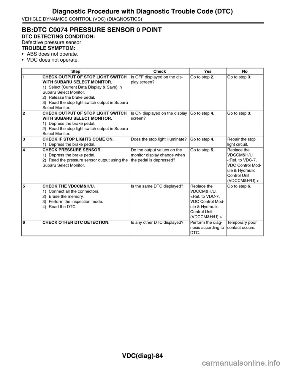
BB:DTC C0074 PRESSURE SENSOR 0 POINT
DTC DETECTING CONDITION:
Defective pressure sensor
TROUBLE SYMPTOM:
•ABS does not operate.
•VDC does not operate.
Step Check Yes No
1CHECK OUTPUT OF STOP LIGHT SWITCH
WITH SUBARU SELECT MONITOR.
1) Select {Current Data Display & Save} in
Subaru Select Monitor.
2) Release the brake pedal.
3) Read the stop light switch output in Subaru
Select Monitor.
Is OFF displayed on the dis-
play screen?
Go to step 2.Go to step 3.
2CHECK OUTPUT OF STOP LIGHT SWITCH
WITH SUBARU SELECT MONITOR.
1) Depress the brake pedal.
2) Read the stop light switch output in Subaru
Select Monitor.
Is ON displayed on the display
screen?
Go to step 4.Go to step 3.
3CHECK IF STOP LIGHTS COME ON.
1) Depress the brake pedal.
Does the stop light illuminate? Go to step 4.Repair the stop
light circuit.
4CHECK PRESSURE SENSOR.
1) Depress the brake pedal.
2) Read the pressure sensor output using the
Subaru Select Monitor.
Do the output values on the
monitor display change when
the pedal is depressed?
Go to step 5.Replace the
VDCCM&H/U.
ule & Hydraulic
Control Unit
(VDCCM&H/U).>
5CHECK THE VDCCM&H/U.
1) Connect all the connectors.
2) Erase the memory.
3) Perform the inspection mode.
4) Read the DTC.
Is the same DTC displayed? Replace the
VDCCM&H/U.
ule & Hydraulic
Control Unit
(VDCCM&H/U).>
Go to step 6.
6CHECK OTHER DTC DETECTION.Is any other DTC displayed? Perform the diag-
nosis according to
DTC.
Te m p o r a r y p o o r
contact occurs.
Page 1081 of 2453
VDC(diag)-89
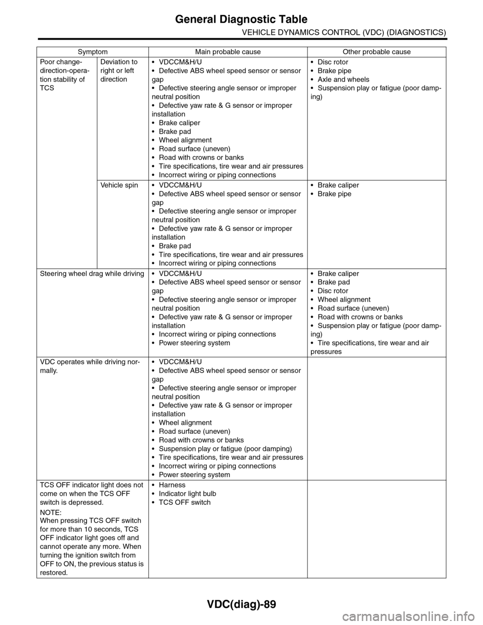
General Diagnostic Table
VEHICLE DYNAMICS CONTROL (VDC) (DIAGNOSTICS)
Po or ch a ng e -
direction-opera-
tion stability of
TCS
Deviation to
right or left
direction
•VDCCM&H/U
•Defective ABS wheel speed sensor or sensor
gap
•Defective steering angle sensor or improper
neutral position
•Defective yaw rate & G sensor or improper
installation
•Brake caliper
•Brake pad
•Wheel alignment
•Road surface (uneven)
•Road with crowns or banks
•Tire specifications, tire wear and air pressures
•Incorrect wiring or piping connections
•Disc rotor
•Brake pipe
•Axle and wheels
•Suspension play or fatigue (poor damp-
ing)
Ve h i c l e s p i n • V D C C M & H / U
•Defective ABS wheel speed sensor or sensor
gap
•Defective steering angle sensor or improper
neutral position
•Defective yaw rate & G sensor or improper
installation
•Brake pad
•Tire specifications, tire wear and air pressures
•Incorrect wiring or piping connections
•Brake caliper
•Brake pipe
Steering wheel drag while driving • VDCCM&H/U
•Defective ABS wheel speed sensor or sensor
gap
•Defective steering angle sensor or improper
neutral position
•Defective yaw rate & G sensor or improper
installation
•Incorrect wiring or piping connections
•Power steering system
•Brake caliper
•Brake pad
•Disc rotor
•Wheel alignment
•Road surface (uneven)
•Road with crowns or banks
•Suspension play or fatigue (poor damp-
ing)
•Tire specifications, tire wear and air
pressures
VDC operates while driving nor-
mally.
•VDCCM&H/U
•Defective ABS wheel speed sensor or sensor
gap
•Defective steering angle sensor or improper
neutral position
•Defective yaw rate & G sensor or improper
installation
•Wheel alignment
•Road surface (uneven)
•Road with crowns or banks
•Suspension play or fatigue (poor damping)
•Tire specifications, tire wear and air pressures
•Incorrect wiring or piping connections
•Power steering system
TCS OFF indicator light does not
come on when the TCS OFF
switch is depressed.
NOTE:When pressing TCS OFF switch
for more than 10 seconds, TCS
OFF indicator light goes off and
cannot operate any more. When
turning the ignition switch from
OFF to ON, the previous status is
restored.
•Harness
•Indicator light bulb
•TCS OFF switch
Symptom Main probable cause Other probable cause
Page 1092 of 2453
VDC-11
VDC Control Module & Hydraulic Control Unit (VDCCM&H/U)
VEHICLE DYNAMICS CONTROL (VDC)
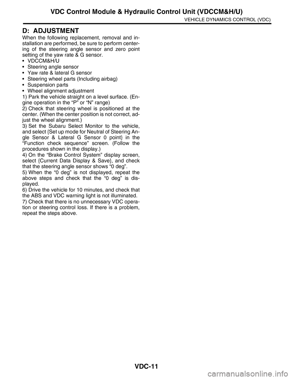
D: ADJUSTMENT
When the following replacement, removal and in-
stallation are performed, be sure to perform center-
ing of the steering angle sensor and zero point
setting of the yaw rate & G sensor.
•VDCCM&H/U
•Steering angle sensor
•Yaw rate & lateral G sensor
•Steering wheel parts (Including airbag)
•Suspension parts
•Wheel alignment adjustment
1) Park the vehicle straight on a level surface. (En-
gine operation in the “P” or “N” range)
2) Check that steering wheel is positioned at the
center. (When the center position is not correct, ad-
just the wheel alignment.)
3) Set the Subaru Select Monitor to the vehicle,
and select {Set up mode for Neutral of Steering An-
gle Sensor & Lateral G Sensor 0 point} in the
“Function check sequence” screen. (Follow the
procedures shown in the display.)
4) On the “Brake Control System” display screen,
select {Current Data Display & Save}, and check
that the steering angle sensor shows “0 deg”.
5) When the “0 deg” is not displayed, repeat the
above steps and check that the “0 deg” is dis-
played.
6) Drive the vehicle for 10 minutes, and check that
the ABS and VDC warning light is not illuminated.
7) Check that there is no unnecessary VDC opera-
tion or steering control loss. If there is a problem,
repeat the steps above.
Page 1095 of 2453
VDC-14
ABS Sequence Control
VEHICLE DYNAMICS CONTROL (VDC)
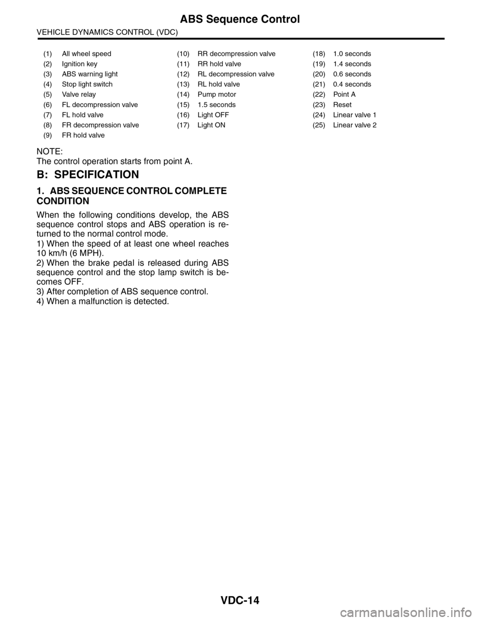
NOTE:
The control operation starts from point A.
B: SPECIFICATION
1. ABS SEQUENCE CONTROL COMPLETE
CONDITION
When the following conditions develop, the ABS
sequence control stops and ABS operation is re-
turned to the normal control mode.
1) When the speed of at least one wheel reaches
10 km/h (6 MPH).
2) When the brake pedal is released during ABS
sequence control and the stop lamp switch is be-
comes OFF.
3) After completion of ABS sequence control.
4) When a malfunction is detected.
(1) All wheel speed (10) RR decompression valve (18) 1.0 seconds
(2) Ignition key (11) RR hold valve (19) 1.4 seconds
(3) ABS warning light (12) RL decompression valve (20) 0.6 seconds
(4) Stop light switch (13) RL hold valve (21) 0.4 seconds
(5) Valve relay (14) Pump motor (22) Point A
(6) FL decompression valve (15) 1.5 seconds (23) Reset
(7) FL hold valve (16) Light OFF (24) Linear valve 1
(8) FR decompression valve (17) Light ON (25) Linear valve 2
(9) FR hold valve
Page 1098 of 2453
VDC-17
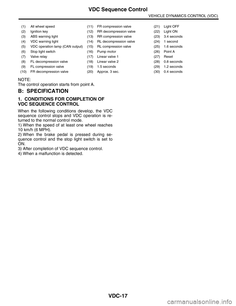
VDC Sequence Control
VEHICLE DYNAMICS CONTROL (VDC)
NOTE:
The control operation starts from point A.
B: SPECIFICATION
1. CONDITIONS FOR COMPLETION OF
VDC SEQUENCE CONTROL
When the following conditions develop, the VDC
sequence control stops and VDC operation is re-
turned to the normal control mode.
1) When the speed of at least one wheel reaches
10 km/h (6 MPH).
2) When the brake pedal is pressed during se-
quence control and the stop light switch is set to
ON.
3) After completion of VDC sequence control.
4) When a malfunction is detected.
(1) All wheel speed (11) FR compression valve (21) Light OFF
(2) Ignition key (12) RR decompression valve (22) Light ON
(3) ABS warning light (13) RR compression valve (23) 3.4 seconds
(4) VDC warning light (14) RL decompression valve (24) 1 second
(5) VDC operation lamp (CAN output) (15) RL compression valve (25) 1.6 seconds
(6) Stop light switch (16) Pump motor (26) Point A
(7) Valve relay (17) Linear valve 1 (27) Reset
(8) FL decompression valve (18) Linear valve 2 (28) 0.8 seconds
(9) FL compression valve (19) 1.5 seconds (29) 1.2 seconds
(10) FR decompression valve (20) Approx. 3 sec. (30) 0.4 seconds
Page 1113 of 2453
WT-7
Aluminum Wheel
WHEEL AND TIRE SYSTEM
3. Aluminum Wheel
A: REMOVAL
1) Apply the parking brake, and position select le-
ver to “P” or “LOW”.
2) Set the shop jacks or a lift to the specified points,
and support the vehicle with its wheels slightly con-
tacting the floor.
3) Loosen the wheel nuts.
4) Raise the vehicle until its wheels are off the
ground using the jack or a lift.
5) Remove the wheel nuts and wheels.
NOTE:
•When removing the wheels, be careful not to
damage the hub bolts.
•Place the wheels with their outer sides facing up-
ward to prevent wheels from being damaged.
B: INSTALLATION
1) Remove dirt from the mating surface of the
wheel and brake rotor.
2) Attach the wheel to the hub by aligning the wheel
bolt holes with the hub bolts.
3) Temporarily attach the wheel nuts to the hub
bolts. (In the case of aluminum wheels, use SUBA-
RU genuine wheel nuts for aluminum wheels.)
4) Tighten the nuts by hand, making sure the wheel
hub hole is aligned correctly to the guide portion of
hub.
5) Tighten the wheel nuts in a diagonal selection to
the specified torque. Use a wheel nut wrench.
Wheel nut tightening torque:
110 N·m (11.2 kgf-m, 81.1 ft-lb)
CAUTION:
•Tighten the wheel nuts in two or three steps
by gradually increasing the torque on opposing
nuts, until they reach the specified torque.
•Do not push the wrench by foot. Always use
both hands when tightening the nuts.
•Make sure the bolt, nut and the nut seating
surface of the wheel are free from oil.
6) If a wheel is removed for replacement or for re-
pair of a puncture, retighten the wheel nuts to the
specified torque after driving 1,000 km (600 miles).
C: INSPECTION
1) Deformation or damage to the rim may cause air
leakage. Check the rim flange for deformation,
cracks or damage, and repair or replace as neces-
sary.
2) Jack-up the vehicle until wheels clear the floor.
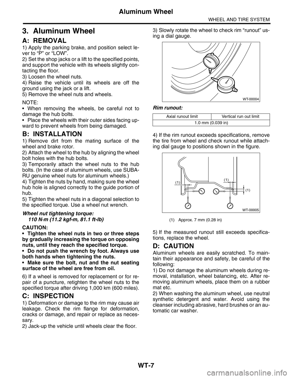
3) Slowly rotate the wheel to check rim “runout” us-
ing a dial gauge.
Rim runout:
4) If the rim runout exceeds specifications, remove
the tire from wheel and check runout while attach-
ing dial gauge to positions shown in the figure.
5) If the measured runout still exceeds specifica-
tions, replace the wheel.
D: CAUTION
Aluminum wheels are easily scratched. To main-
tain their appearance and safety, be careful of the
following:
1) Do not damage the aluminum wheels during re-
moval, installation, wheel balancing, etc. After re-
moving aluminum wheels, place them on a rubber
mat etc.
2) When washing the aluminum wheel, use neutral
synthetic detergent and water. Avoid using the
cleanser including abrasive, hard brushes or an au-
tomatic car washer.
Axial runout limit Vertical run out limit
1.0 mm (0.039 in)
(1) Approx. 7 mm (0.28 in)
WT-00004
WT-00005
(1)
(1)
(1)
Page 1116 of 2453
WT-10
“T–type” Tire
WHEEL AND TIRE SYSTEM
5. “T–type” Tire
A: NOTE
“T–type” tire for temporary use is equipped as a
spare tire.
CAUTION:
•Do not drive at a speed greater than 100 km/h
(62 MPH).
•For the model with tire pressure monitoring
system, the indicator light may blink when run-
ning with the “T-type” tire.
B: REPLACEMENT
Refer to Aluminum Wheels for removal and instal-
lation procedures of the “T–type”.
CAUTION:
The “T–type” tire is only for temporary use. Re-
place with a conventional tire as soon as possi-
ble.
C: INSPECTION
1) Check the tire air pressure.
Specifications:
420 kPa (4.2 kg/cm2, 60 psi)
2) Take stones, glass, nails, etc. out of the tread
groove.
3) Check the tires for deformation, cracks, partial
wear, or wear.
CAUTION:
Replace the tire with a new one if defective.
Page 1163 of 2453
EN(H6DO)(diag)-2
Basic Diagnostic Procedure
ENGINE (DIAGNOSTICS)
1. Basic Diagnostic Procedure
A: PROCEDURE
1. ENGINE
Step Check Yes No
1CHECK ENGINE START FAILURE.
1) Ask the customer when and how the trou-
ble occurred using the interview check list.
2) Start the engine.
Does the engine start? Go to step 2.Inspection using
“Diagnostics for
Engine Start Fail-
ure”.
57, Diagnostics for
Engine Starting
Fai lu r e.>
2CHECK ILLUMINATION OF MALFUNCTION
INDICATOR LIGHT.
Does the malfunction indicator
light illuminate?
Go to step 3.Inspection using
“General Diagnos-
tic Table”
392, INSPEC-
TION, General
Diagnostic Table.>
3CHECK INDICATION OF DTC ON DISPLAY.
1) Turn the ignition switch to OFF.
2) Connect the Subaru Select Monitor or gen-
eral scan tool to data link connector.
3) Turn the ignition switch to ON, and the Sub-
aru Select Monitor power switch to ON.
4) Read DTC on Subaru Select Monitor or
general scan tool.
Is DTC displayed on the Sub-
aru Select Monitor or general
scan tool?
Record the DTC.
Repair the trouble
cause.
69, List of Diag-
nostic Trouble
Code (DTC).> Go
to step 4.
Repair the related
parts.
NOTE:
If DTC is not
shown on display
although the mal-
function indicator
light illuminates,
perform the diag-
nosis of malfunc-
tion indicator light
circuit or combina-
tion meter.
48, Malfunction In-
dicator Light.>
4PERFORM DIAGNOSIS
1) Perform the clear memory mode.
2) Perform the inspection mode.
Is DTC displayed on the Sub-
aru Select Monitor or general
scan tool?
Inspect using
“Diagnostic Proce-
dure with Diagnos-
tic Trouble Code
(DTC)”.
77, Diagnostic
Procedure with
Diagnostic Trou-
ble Code (DTC).>
Finish the diagno-
sis.