Page 1130 of 2453

CO(H6DO)-11
Engine Coolant
COOLING
11) Wait for one minute after the engine stops,
open the radiator cap. If the engine coolant level
drops, add engine coolant into radiator up to the fill-
er neck position.
12) Perform the procedures 10) and 11) again.
13) Attach the radiator cap and reservoir tank cap
properly.
14) Start the engine and operate the heater at max-
imum hot position and the blower speed setting to
“LO.”
15) Run the engine at 2,000 rpm or less until radia-
tor fan starts and stops.
NOTE:
•Be careful with the engine coolant temperature
gauge to prevent overheating.
•If the radiator hose becomes harden with the
pressure of engine coolant, air bleeding operation
seems to be almost completed.
16) Stop the engine and wait until the engine cool-
ant temperature lowers to 30°C (86°F).
17) Open the radiator cap. If the engine coolant lev-
el drops, add engine coolant into radiator up to the
filler neck position and reservoir tank to the “FULL”
level.
18) Attach the radiator cap and reservoir tank cap
properly.
19) Set the heater setting to maximum hot position
and the blower speed setting to “LO” and start the
engine. Perform racing at less than 3,000 rpm. If
the flowing sound is heard at this time, perform the
procedures from 15) again.
B: INSPECTION
1. RELATIONSHIP OF SUBARU COOLANT
CONCENTRATION AND FREEZING TEM-
PERATURE
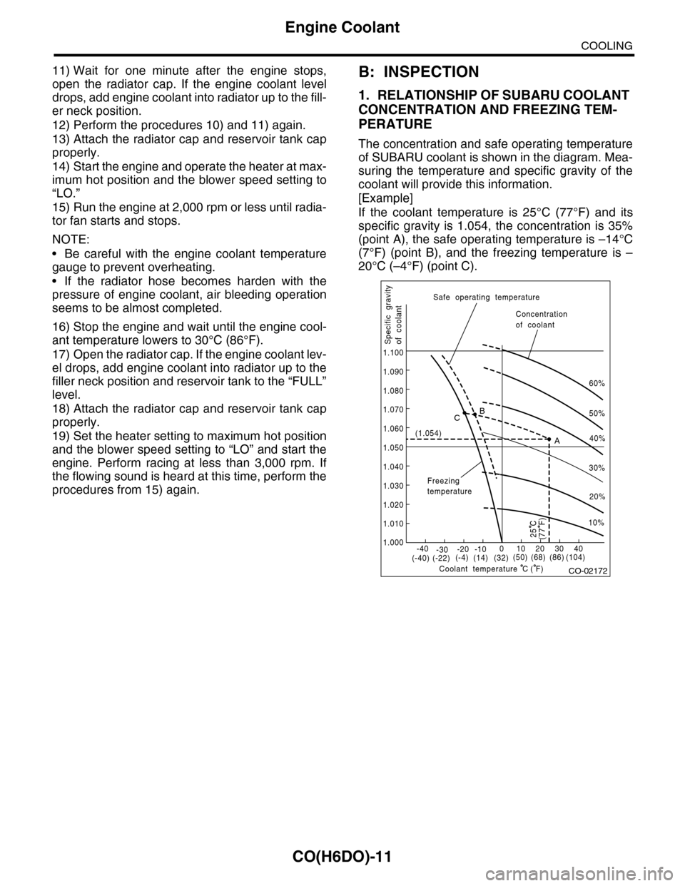
The concentration and safe operating temperature
of SUBARU coolant is shown in the diagram. Mea-
suring the temperature and specific gravity of the
coolant will provide this information.
[Example]
If the coolant temperature is 25°C (77°F) and its
specific gravity is 1.054, the concentration is 35%
(point A), the safe operating temperature is –14°C
(7°F) (point B), and the freezing temperature is –
20°C (–4°F) (point C).
CO-02172
60%
(1.054)
1.000
1.010
1.020
1.030
1.040
1.050
1.060
1.070
1.080
1.090
1.100
Safe operating temperature
Freezingtemperature
Concentrationof coolant
Specific gravityof coolant
Coolant temperature
B
A
C
-40(-40) (-22)(-4)(14)(32)(50) (68) (86)
( F)
(104)-30-20 -10010203040
(77 F)
50%
40%
30%
20%
25 C
10%
C
Page 1131 of 2453

CO(H6DO)-12
Engine Coolant
COOLING
2. PROCEDURE TO ADJUST THE CON-
CENTRATION OF THE COOLANT
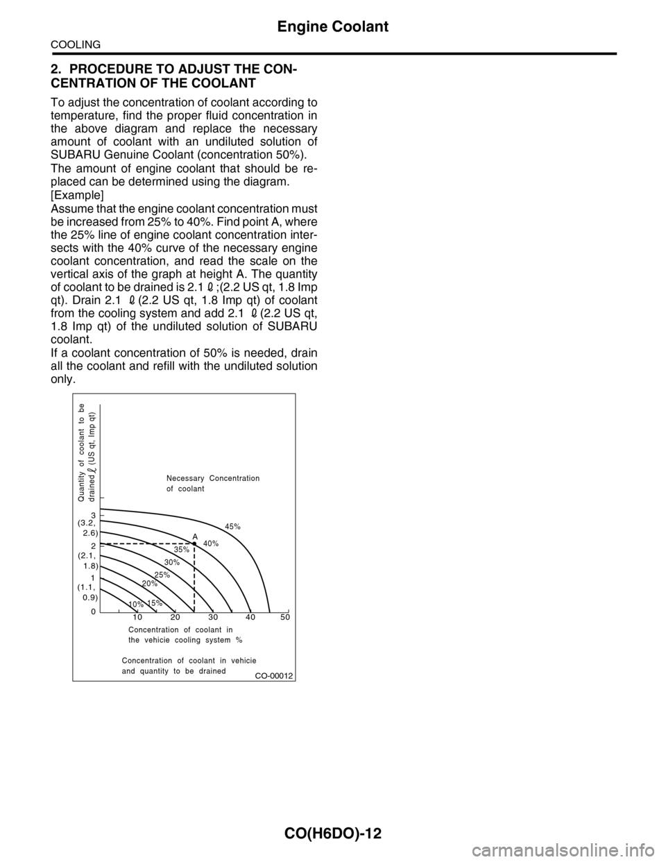
To adjust the concentration of coolant according to
temperature, find the proper fluid concentration in
the above diagram and replace the necessary
amount of coolant with an undiluted solution of
SUBARU Genuine Coolant (concentration 50%).
The amount of engine coolant that should be re-
placed can be determined using the diagram.
[Example]
Assume that the engine coolant concentration must
be increased from 25% to 40%. Find point A, where
the 25% line of engine coolant concentration inter-
sects with the 40% curve of the necessary engine
coolant concentration, and read the scale on the
vertical axis of the graph at height A. The quantity
of coolant to be drained is 2.12;(2.2 US qt, 1.8 Imp
qt). Drain 2.1 2(2.2 US qt, 1.8 Imp qt) of coolant
from the cooling system and add 2.1 2(2.2 US qt,
1.8 Imp qt) of the undiluted solution of SUBARU
coolant.
If a coolant concentration of 50% is needed, drain
all the coolant and refill with the undiluted solution
only.
CO-00012
100
1
2
3
(1.1, 0.9)
(2.1, 1.8)
(3.2, 2.6)
10%15%
25%20%
30%
35%40%
45%A
20 30 40 50
Concentration of coolant in vehicieand quantity to be drained
Quantity of coolant to bedrained (US qt, Imp qt)
Necessary Concentrationof coolant
Concentration of coolant inthe vehicie cooling system %
Page 1149 of 2453

CO(H6DO)-30
Engine Cooling System Trouble in General
COOLING
12.Engine Cooling System Trouble in General
A: INSPECTION
Tr o u b l e P o s s i b l e c a u s e C o r r e c t i v e a c t i o n
Overheating
a. Insufficient engine coolantReplenish engine coolant, inspect for leakage, and
repair it if necessary.
b. De fe c ti ve t he r mo st a t Rep la c e.
c. Malfunction of water pump Replace.
d. Clogged engine coolant passage Clean.
e. Improper ignition timing
Inspect and repair ignition control system.
EN(H6DO)(diag)-2, PROCEDURE, Basic Diagnostic
Procedure.>
f. Clogged or leaking radiator Clean, repair or replace.
g. Improper engine oil in engine coolant Replace engine coolant.
h. Air/fuel mixture ratio too lean
Inspect and repair the fuel injection system.
EN(H6DO)(diag)-2, PROCEDURE, Basic Diagnostic
Procedure.>
i. Excessive back pressure in exhaust system Clean or replace.
j. Insufficient clearance between piston and cylinder Adjust or replace.
k. Slipping clutch Correct or replace.
l. Dragging brake Adjust.
m. Faulty transmission gear oil Replace.
n. Malfunction of radiator fanInspect the radiator fan relay, engine coolant tempera-
ture sensor or fan motor and replace them.
Over-coolinga. Ambient temperature extremely low Partly cover radiator front area.
b. De fe c ti ve t he r mo st a t Rep la c e.
Engine coolant
leaks
a. Loosened or damaged connecting units on hoses Correct or replace.
b. L ea k ag e f r o m wat e r pu mp Rep la c e.
c. Leakage from water pipe Correct or replace.
d. Leakage around cylinder head gasket Retighten cylinder head bolts or replace gasket.
e. Damaged or cracked cylinder head and crankcase Correct or replace.
f. Damaged or cracked ther mostat case Correct or replace.
g. Leakage from radiator Correct or replace.
Strange noise
a. Defective drive belt Replace.
b. De fe c ti ve ra di a t or fan Rep la c e.
c. Defective water pump bearing Replace water pump.
d. Defective water pump mechanical seal Replace water pump.
Page 1151 of 2453
EC(H6DO)-3
Front Catalytic Converter
EMISSION CONTROL (AUX. EMISSION CONTROL DEVICES)
2. Front Catalytic Converter
A: REMOVAL
The front and rear catalytic converters are integrat-
ed into the front exhaust pipe therefore, refer to
“Front Exhaust Pipe” for the removal procedure.
Pipe.>
B: INSTALLATION
The front and rear catalytic converters are integrat-
ed into front exhaust pipe as one unit; therefore, re-
fer to “Front Exhaust Pipe” for installation
procedure.
Front Exhaust Pipe.>
C: INSPECTION
1) Check the connections and welds for exhaust
leaks.
2) Check for hole or rust.
(A) Front catalytic converter
(B) Rear catalytic converter
(A) Front catalytic converter
(B) Rear catalytic converter
(A)
(B)
EC-02018
(A)
(B)
EC-02018
Page 1152 of 2453
EC(H6DO)-4
Rear Catalytic Converter
EMISSION CONTROL (AUX. EMISSION CONTROL DEVICES)
3. Rear Catalytic Converter
A: REMOVAL
The front and rear catalytic converters are integrat-
ed into the front exhaust pipe therefore, refer to
“Front Exhaust Pipe” for the removal procedure.
Pipe.>
B: INSTALLATION
The front and rear catalytic converters are integrat-
ed into front exhaust pipe as one unit; therefore, re-
fer to “Front Exhaust Pipe” for installation
procedure.
Front Exhaust Pipe.>
C: INSPECTION
1) Check the connections and welds for exhaust
leaks.
2) Check for hole or rust.
(A) Front catalytic converter
(B) Rear catalytic converter
(A) Front catalytic converter
(B) Rear catalytic converter
(A)
(B)
EC-02018
(A)
(B)
EC-02018
Page 1155 of 2453
EC(H6DO)-7
Fuel Level Sensor
EMISSION CONTROL (AUX. EMISSION CONTROL DEVICES)
6. Fuel Level Sensor
A: REMOVAL
For removal procedure, refer to “FU(H6DO)” sec-
tion.
el Sensor.>
B: INSTALLATION
For installation procedure, refer to “FU(H6DO)”
section.
Fuel Level Sensor.>
Page 1156 of 2453
EC(H6DO)-8
Fuel Temperature Sensor
EMISSION CONTROL (AUX. EMISSION CONTROL DEVICES)
7. Fuel Temperature Sensor
A: REMOVAL
The fuel temperature sensor and fuel level sensor
are integrated into one unit; therefore, refer to “Fuel
Level Sensor” for removal procedure.
FU(H6DO)-45, REMOVAL, Fuel Level Sensor.>
B: INSTALLATION
The fuel temperature sensor and fuel level sensor
are integrated into one unit; therefore, refer to “Fuel
Level Sensor” for installation procedure.
FU(H6DO)-45, INSTALLATION, Fuel Level Sen-
sor.>
Page 1157 of 2453
EC(H6DO)-9
Fuel Sub Level Sensor
EMISSION CONTROL (AUX. EMISSION CONTROL DEVICES)
8. Fuel Sub Level Sensor
A: REMOVAL
For removal procedure, refer to “FU(H6DO)” sec-
tion.
Level Sensor.>
B: INSTALLATION
For installation procedure, refer to “FU(H6DO)”
section.
Fuel Sub Level Sensor.>