2009 SUBARU TRIBECA ac 25 procedure
[x] Cancel search: ac 25 procedurePage 1163 of 2453
EN(H6DO)(diag)-2
Basic Diagnostic Procedure
ENGINE (DIAGNOSTICS)
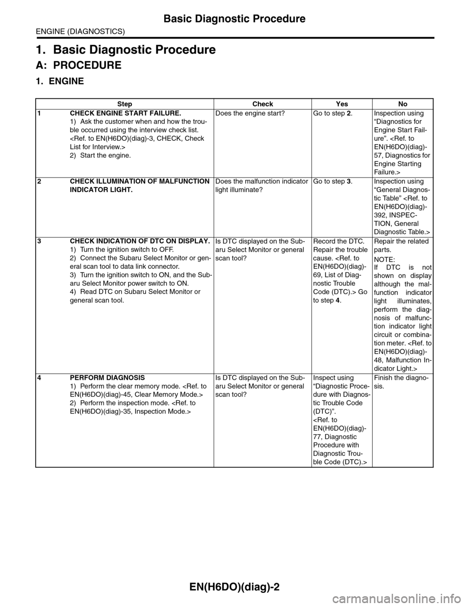
1. Basic Diagnostic Procedure
A: PROCEDURE
1. ENGINE
Step Check Yes No
1CHECK ENGINE START FAILURE.
1) Ask the customer when and how the trou-
ble occurred using the interview check list.
2) Start the engine.
Does the engine start? Go to step 2.Inspection using
“Diagnostics for
Engine Start Fail-
ure”.
57, Diagnostics for
Engine Starting
Fai lu r e.>
2CHECK ILLUMINATION OF MALFUNCTION
INDICATOR LIGHT.
Does the malfunction indicator
light illuminate?
Go to step 3.Inspection using
“General Diagnos-
tic Table”
392, INSPEC-
TION, General
Diagnostic Table.>
3CHECK INDICATION OF DTC ON DISPLAY.
1) Turn the ignition switch to OFF.
2) Connect the Subaru Select Monitor or gen-
eral scan tool to data link connector.
3) Turn the ignition switch to ON, and the Sub-
aru Select Monitor power switch to ON.
4) Read DTC on Subaru Select Monitor or
general scan tool.
Is DTC displayed on the Sub-
aru Select Monitor or general
scan tool?
Record the DTC.
Repair the trouble
cause.
69, List of Diag-
nostic Trouble
Code (DTC).> Go
to step 4.
Repair the related
parts.
NOTE:
If DTC is not
shown on display
although the mal-
function indicator
light illuminates,
perform the diag-
nosis of malfunc-
tion indicator light
circuit or combina-
tion meter.
48, Malfunction In-
dicator Light.>
4PERFORM DIAGNOSIS
1) Perform the clear memory mode.
2) Perform the inspection mode.
Is DTC displayed on the Sub-
aru Select Monitor or general
scan tool?
Inspect using
“Diagnostic Proce-
dure with Diagnos-
tic Trouble Code
(DTC)”.
77, Diagnostic
Procedure with
Diagnostic Trou-
ble Code (DTC).>
Finish the diagno-
sis.
Page 1166 of 2453
EN(H6DO)(diag)-5
General Description
ENGINE (DIAGNOSTICS)
3. General Description
A: CAUTION
1) Airbag system wiring harness is routed near the
ECM, main relay and fuel pump relay.
CAUTION:
•All airbag system wiring harnesses and con-
nectors are colored yellow. Do not use electri-
cal test equipment on these circuits.
•Be careful not to damage the airbag system
wiring harness when servicing the ECM, TCM,
main relay and fuel pump relay.
2) Never connect the battery in reverse polarity.
•The ECM will be destroyed instantly.
•The fuel injector and other parts will be dam-
aged.
3) Do not disconnect the battery terminals while the
engine is running.
A large counter electromotive force will be generat-
ed in the generator, and this voltage may damage
electronic parts such as ECM etc.
4) Before disconnecting the connectors of each
sensor and ECM, be sure to turn the ignition switch
to OFF. Perform the clear memory mode after con-
necting the connectors.
5) Poor contact has been identified as a primary
cause of this problem. Measure the voltage or re-
sistance of individual sensor or all electrical control
modules using a tapered pin with a diameter of less
than 0.64 mm (0.025 in). Do not insert the pin more
than 5 mm (0.20 in) into the part.
6) Remove the ECM from the located position after
disconnecting two cables on battery.
Otherwise, the ECM may be damaged.
CAUTION:
When replacing the ECM, be careful not to use
the wrong spec. ECM to avoid any damage on
the fuel injection system.
7) Connectors of each sensor in the engine com-
partment and the harness connectors on the en-
gine side and body side are all designed to be
waterproof. Even if the connectors are waterproof,
take care not to allow water to get into them when
washing the vehicle, or when servicing the vehicle
in rainy weather.
8) Use ECM mounting stud bolts as the grounding
point to chassis when measuring voltage and resis-
tance in the passenger compartment.
9) Use the engine ground terminal or engine as-
sembly as the grounding point to chassis when
measuring the voltage and resistance in engine
compartment.
10) Every MFI-related part is a precision part. Do
not drop them.
11) Observe the following cautions when installing
a radio in MFI equipped models.
CAUTION:
•The antenna must be kept as far apart as pos-
sible from control unit. (The ECM is located un-
der the steering column, inside of the
instrument panel lower trim panel.)
•The antenna feeder must be placed as far apart
as possible from the ECM and MFI harness.
•Carefully adjust the antenna for correct
matching.
•When mounting a large power type radio, pay
special attention to the three items mentioned
above.
•Incorrect installation of the radio may affect
the operation of ECM.
12) Release the pressure in the fuel system before
disconnecting the fuel hose. If engine starts during
this operation, run it until it stops.
13) For the model with ABS, the ABS warning light
may illuminate when performing driving test with
jacked-up or lifted-up condition, but this is not a
system malfunction. The reason for this is the
speed difference between the front and rear
wheels. After diagnosis of engine control system,
perform the ABS memory clear procedure of self-
diagnosis function.
B: INSPECTION
Before performing diagnostics, check the following
item which might affect engine problems.
1. BATTERY
1) Measure the battery voltage and specific gravity
of electrolyte.
Standard voltage: 12 V
Specific gravity: Above 1.260
2) Check the condition of the main and other fuses,
and harnesses and connectors. Also check for
proper grounding.
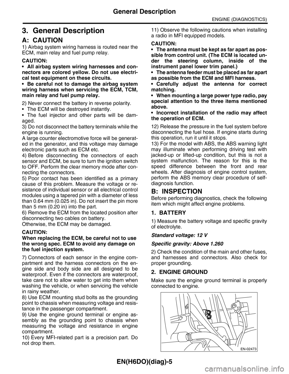
2. ENGINE GROUND
Make sure the engine ground terminal is properly
connected to engine.
EN-02473
Page 1183 of 2453
EN(H6DO)(diag)-22
General Scan Tool
ENGINE (DIAGNOSTICS)
8. General Scan Tool
A: OPERATION
1. HOW TO USE GENERAL SCAN TOOL
1) Prepare a scan tool (general scan tool) required
by SAE J1978.
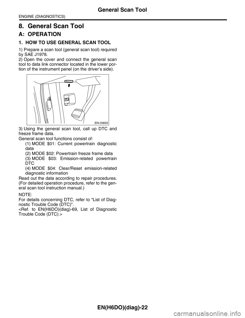
2) Open the cover and connect the general scan
tool to data link connector located in the lower por-
tion of the instrument panel (on the driver’s side).
3) Using the general scan tool, call up DTC and
freeze frame data.
General scan tool functions consist of:
(1) MODE $01: Current powertrain diagnostic
data
(2) MODE $02: Powertrain freeze frame data
(3) MODE $03: Emission-related powertrain
DTC
(4) MODE $04: Clear/Reset emission-related
diagnostic information
Read out the data according to repair procedures.
(For detailed operation procedure, refer to the gen-
eral scan tool instruction manual.)
NOTE:
For details concerning DTC, refer to “List of Diag-
nostic Trouble Code (DTC)”.
EN-03693
Page 1191 of 2453
EN(H6DO)(diag)-30
Subaru Select Monitor
ENGINE (DIAGNOSTICS)
NOTE:
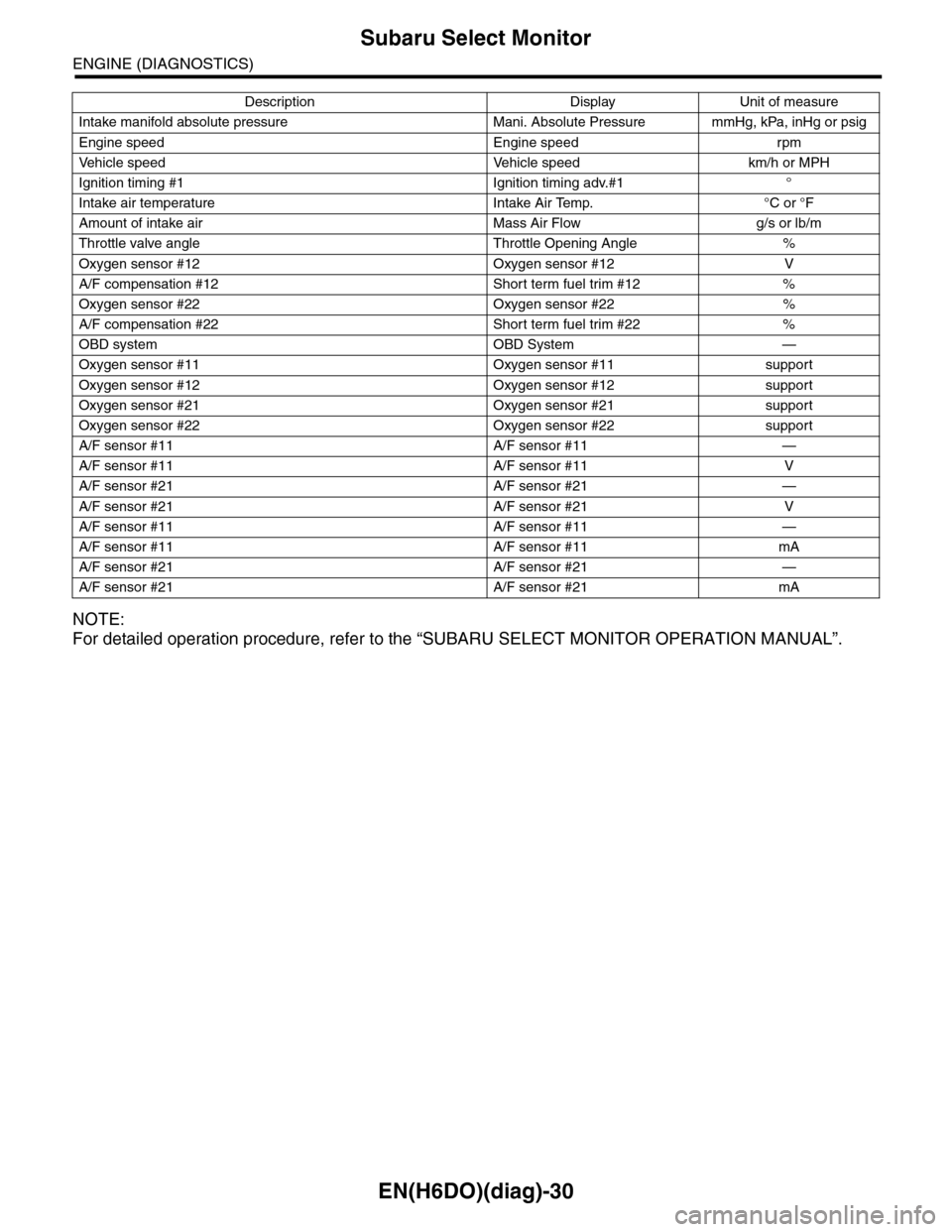
For detailed operation procedure, refer to the “SUBARU SELECT MONITOR OPERATION MANUAL”.
Intake manifold absolute pressure Mani. Absolute Pressure mmHg, kPa, inHg or psig
Engine speed Engine speed rpm
Ve h i c l e s p e e d Ve h i c l e s p e e d k m / h o r M P H
Ignition timing #1 Ignition timing adv.#1 °
Intake air temperature Intake Air Temp. °C or °F
Amount of intake air Mass Air Flow g/s or lb/m
Throttle valve angle Throttle Opening Angle %
Oxygen sensor #12 Oxygen sensor #12 V
A/F compensation #12 Short term fuel trim #12 %
Oxygen sensor #22 Oxygen sensor #22 %
A/F compensation #22 Short term fuel trim #22 %
OBD system OBD System —
Oxygen sensor #11 Oxygen sensor #11 support
Oxygen sensor #12 Oxygen sensor #12 support
Oxygen sensor #21 Oxygen sensor #21 support
Oxygen sensor #22 Oxygen sensor #22 support
A/F sensor #11 A/F sensor #11 —
A/F sensor #11 A/F sensor #11 V
A/F sensor #21 A/F sensor #21 —
A/F sensor #21 A/F sensor #21 V
A/F sensor #11 A/F sensor #11 —
A/F sensor #11 A/F sensor #11 mA
A/F sensor #21 A/F sensor #21 —
A/F sensor #21 A/F sensor #21 mA
Description Display Unit of measure
Page 1192 of 2453
![SUBARU TRIBECA 2009 1.G Service Workshop Manual EN(H6DO)(diag)-31
Subaru Select Monitor
ENGINE (DIAGNOSTICS)
6. READ FREEZE FRAME DATA FOR ENGINE (OBD MODE)
1) On the «Main Menu» display screen, select the {Each System Check} and press the [YES] SUBARU TRIBECA 2009 1.G Service Workshop Manual EN(H6DO)(diag)-31
Subaru Select Monitor
ENGINE (DIAGNOSTICS)
6. READ FREEZE FRAME DATA FOR ENGINE (OBD MODE)
1) On the «Main Menu» display screen, select the {Each System Check} and press the [YES]](/manual-img/17/7322/w960_7322-1191.png)
EN(H6DO)(diag)-31
Subaru Select Monitor
ENGINE (DIAGNOSTICS)
6. READ FREEZE FRAME DATA FOR ENGINE (OBD MODE)
1) On the «Main Menu» display screen, select the {Each System Check} and press the [YES] key.
2) On the «System Selection Menu» display screen, select the {Engine} and press the [YES] key.
3) Press the [YES] key after the information of engine type has been displayed.
4) On the «Engine Diagnosis» display screen, select the {OBD System} and press the [YES] key.
5) On the «OBD Menu» display screen, select the {Freeze Frame Data} and press the [YES] key.
•A list of the support data is shown in the following table.
NOTE:
For detailed operation procedure, refer to the “SUBARU SELECT MONITOR OPERATION MANUAL”.
Description Display Unit of measure
DTC of freeze frame data Freeze frame data DTC
Air fuel ratio control system for bank 1 Fuel system for Bank1 —
Air fuel ratio control system for bank 2 Fuel system for Bank2 —
Engine load data Engine Load %
Engine coolant temperature signal Coolant Temp. °C or °F
Short term fuel trim by front oxygen (A/F) sensor (Bank 1) Short term fuel trim B1 %
Long term fuel trim by front oxygen (A/F) sensor (Bank 1) Long term fuel trim B1 %
Short term fuel trim by front oxygen (A/F) sensor (Bank 2) Short term fuel trim B2 %
Long term fuel trim by front oxygen (A/F) sensor (Bank 2) Long term fuel trim B2 %
Intake manifold absolute pressure signal Mani. Absolute Pressure mmHg, kPa, inHg or psig
Engine speed signal Engine Speed rpm
Ve h i c l e s p e e d s i g n a l Ve h i c l e S p e e d k m / h o r M P H
Ignition timing #1 Ignition timing adv. #1 °
Intake air temperature Intake Air Temp. °C
Amount of intake air Mass Air Flow g/s
Throttle valve angle Throttle Opening Angle %
Oxygen sensor #12 Oxygen sensor #12 V
A/F compensation #12 Short term fuel trim #12 %
Oxygen sensor #22 Oxygen sensor #22 V
A/F compensation #12 Short term fuel trim #22 %
Oxygen sensor #11 Oxygen sensor #11 support
Oxygen sensor #12 Oxygen sensor #12 support
Oxygen sensor #21 Oxygen sensor #21 support
Oxygen sensor #22 Oxygen sensor #22 support
Page 1193 of 2453
![SUBARU TRIBECA 2009 1.G Service Workshop Manual EN(H6DO)(diag)-32
Subaru Select Monitor
ENGINE (DIAGNOSTICS)
7. LED OPERATION MODE FOR ENGINE
1) On the «Main Menu» display screen, select the {Each System Check} and press the [YES] key.
2) On the SUBARU TRIBECA 2009 1.G Service Workshop Manual EN(H6DO)(diag)-32
Subaru Select Monitor
ENGINE (DIAGNOSTICS)
7. LED OPERATION MODE FOR ENGINE
1) On the «Main Menu» display screen, select the {Each System Check} and press the [YES] key.
2) On the](/manual-img/17/7322/w960_7322-1192.png)
EN(H6DO)(diag)-32
Subaru Select Monitor
ENGINE (DIAGNOSTICS)
7. LED OPERATION MODE FOR ENGINE
1) On the «Main Menu» display screen, select the {Each System Check} and press the [YES] key.
2) On the «System Selection Menu» display screen, select the {Engine} and press the [YES] key.
3) Press the [YES] key after the information of engine type has been displayed.
4) On the «Engine Diagnosis» display screen, select the {Current Data Display/Save}, and then press the
[YES] key.
5) On the «Data Display» screen, select the {Data LED Display} and press the [YES] key.
6) Using the scroll key, scroll the display screen up or down until the desired data is shown.
•A list of the support data is shown in the following table.
NOTE:
For detailed operation procedure, refer to the “SUBARU SELECT MONITOR OPERATION MANUAL”.
Description Display Message When LED “ON” required
Te s t m o d e s i g n a l Te s t m o d e t e r m i n a l D c h e c k / U c h e c k D c h e c k
Neutral position switch signal Neutral SW Neutral/Other than neutral Neutral
Idle switch signal Soft idle SW Idle/Other than idle In idle
Ignition switch signal Ignition SW ON Input/OFF Input ON input
Pow er s te e r in g sw it c h s ig n al Pow er s te e r in g S W ON I np u t/ O FF I np u t ON i np ut
Air conditioning switch signal A/C SW ON Input/OFF Input ON input
Starter switch signal Starter SW ON Input/OFF Input ON input
Fr o nt ox yg e n mo n it o r 1 Ft O 2 mo n it o r 1 Le a n/ Ri ch Ric h
Fr o nt ox yg e n mo n it o r 2 Ft O 2 mo n it o r 2 Le a n/ Ri ch Ric h
Knocking signal Knock signal Yes/No Yes
Crankshaft position sensor signal Crankshaft angle signal Yes/No Yes
Camshaft position sensor signal Camshaft angle signal Yes/No Yes
Rear defogger switch signal Rear defogger SW ON Input/OFF Input ON input
Blower fan switch signal Blower fan SW ON Input/OFF Input ON input
Light switch signal Light SW ON Input/OFF Input ON input
Wiper switch signal Wiper SW ON Input/OFF Input ON input
A/C middle pressure switch signal A/C middle pressure SW ON Input/OFF Input ON input
Air conditioner compressor relay sig-
nalCompressor relay ON output/OFF output ON output
Drain valve signal Vent. Solenoid Valve ON or OFF When drain valve is ON.
AT r e t a r d a n g l e d e m a n d s i g n a l AT r e t a r d a n g l e d e m a n d Ye s / N o Ye s
AT f u e l c u t s i g n a l AT f u e l c u t Ye s / N o Ye s
VDC torque down prohibition output Torque down output ON/OFF Prohibition
VDC torque down demand Torque down demand Yes/No Yes
AT c o o r d i n a t e p e r m i s s i o n s i g n a lAT c o o r d i n a t e p e r m i s s i o n
signalON/OFF Permission
Electronic throttle control motor relay
signalETC motor relay ON/OFF ON
Stop light switch signal Stop SW ON Input/OFF Input ON input
SET/COAST switch signal SET/CST SW ON Input/OFF Input ON input
RESUME/ACCEL switch signal RES/ACC SW ON Input/OFF Input ON input
Brake switch signal Brake SW ON Input/OFF Input ON input
Main switch signal Main SW ON Input/OFF Input ON input
Body integrated unit data reception Body Int. Unit Data Yes/No Yes
Body integrated unit counter update Body Int. Unit Count Yes/No Yes
Cruise control cancel switch signal CC Cancel SW ON Input/OFF Input ON input
Va r i a b l e va l v e l i f t d i a g n o s i s o i l p r e s -
sure switch signal 1Oil Temperature SW1 ON/OFF ON
Va r i a b l e va l v e l i f t d i a g n o s i s o i l p r e s -
sure switch signal 2Oil Temperature SW2 ON/OFF ON
Page 1194 of 2453
![SUBARU TRIBECA 2009 1.G Service Workshop Manual EN(H6DO)(diag)-33
Subaru Select Monitor
ENGINE (DIAGNOSTICS)
8. VIN REGISTRATION
1) On the «Main Menu» display screen, select the {Each System Check} and press the [YES] key.
2) On the «System Sele SUBARU TRIBECA 2009 1.G Service Workshop Manual EN(H6DO)(diag)-33
Subaru Select Monitor
ENGINE (DIAGNOSTICS)
8. VIN REGISTRATION
1) On the «Main Menu» display screen, select the {Each System Check} and press the [YES] key.
2) On the «System Sele](/manual-img/17/7322/w960_7322-1193.png)
EN(H6DO)(diag)-33
Subaru Select Monitor
ENGINE (DIAGNOSTICS)
8. VIN REGISTRATION
1) On the «Main Menu» display screen, select the {Each System Check} and press the [YES] key.
2) On the «System Selection Menu» display screen, select the {Engine} and press the [YES] key.
3) Press the [YES] key after the information of engine type has been displayed.
4) On the «Engine Diagnosis» display screen, select the {VIN Registration} and press the [YES] key.
5) Perform the procedure shown on display screen.
NOTE:
For detailed operation procedure, refer to the “SUBARU SELECT MONITOR OPERATION MANUAL”.
Page 1195 of 2453
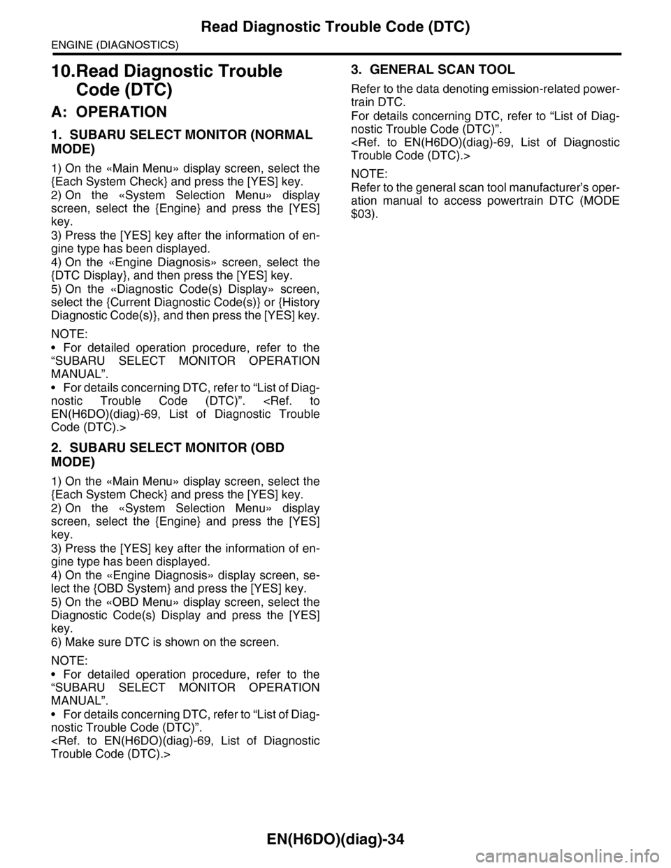
EN(H6DO)(diag)-34
Read Diagnostic Trouble Code (DTC)
ENGINE (DIAGNOSTICS)
10.Read Diagnostic Trouble
Code (DTC)
A: OPERATION
1. SUBARU SELECT MONITOR (NORMAL
MODE)
1) On the «Main Menu» display screen, select the
{Each System Check} and press the [YES] key.
2) On the «System Selection Menu» display
screen, select the {Engine} and press the [YES]
key.
3) Press the [YES] key after the information of en-
gine type has been displayed.
4) On the «Engine Diagnosis» screen, select the
{DTC Display}, and then press the [YES] key.
5) On the «Diagnostic Code(s) Display» screen,
select the {Current Diagnostic Code(s)} or {History
Diagnostic Code(s)}, and then press the [YES] key.
NOTE:
•For detailed operation procedure, refer to the
“SUBARU SELECT MONITOR OPERATION
MANUAL”.
•For details concerning DTC, refer to “List of Diag-
nostic Trouble Code (DTC)”.
Code (DTC).>
2. SUBARU SELECT MONITOR (OBD
MODE)
1) On the «Main Menu» display screen, select the
{Each System Check} and press the [YES] key.
2) On the «System Selection Menu» display
screen, select the {Engine} and press the [YES]
key.
3) Press the [YES] key after the information of en-
gine type has been displayed.
4) On the «Engine Diagnosis» display screen, se-
lect the {OBD System} and press the [YES] key.
5) On the «OBD Menu» display screen, select the
Diagnostic Code(s) Display and press the [YES]
key.
6) Make sure DTC is shown on the screen.
NOTE:
•For detailed operation procedure, refer to the
“SUBARU SELECT MONITOR OPERATION
MANUAL”.
•For details concerning DTC, refer to “List of Diag-
nostic Trouble Code (DTC)”.
3. GENERAL SCAN TOOL
Refer to the data denoting emission-related power-
train DTC.
For details concerning DTC, refer to “List of Diag-
nostic Trouble Code (DTC)”.
NOTE:
Refer to the general scan tool manufacturer’s oper-
ation manual to access powertrain DTC (MODE
$03).