Page 1076 of 2453
VDC(diag)-84
Diagnostic Procedure with Diagnostic Trouble Code (DTC)
VEHICLE DYNAMICS CONTROL (VDC) (DIAGNOSTICS)
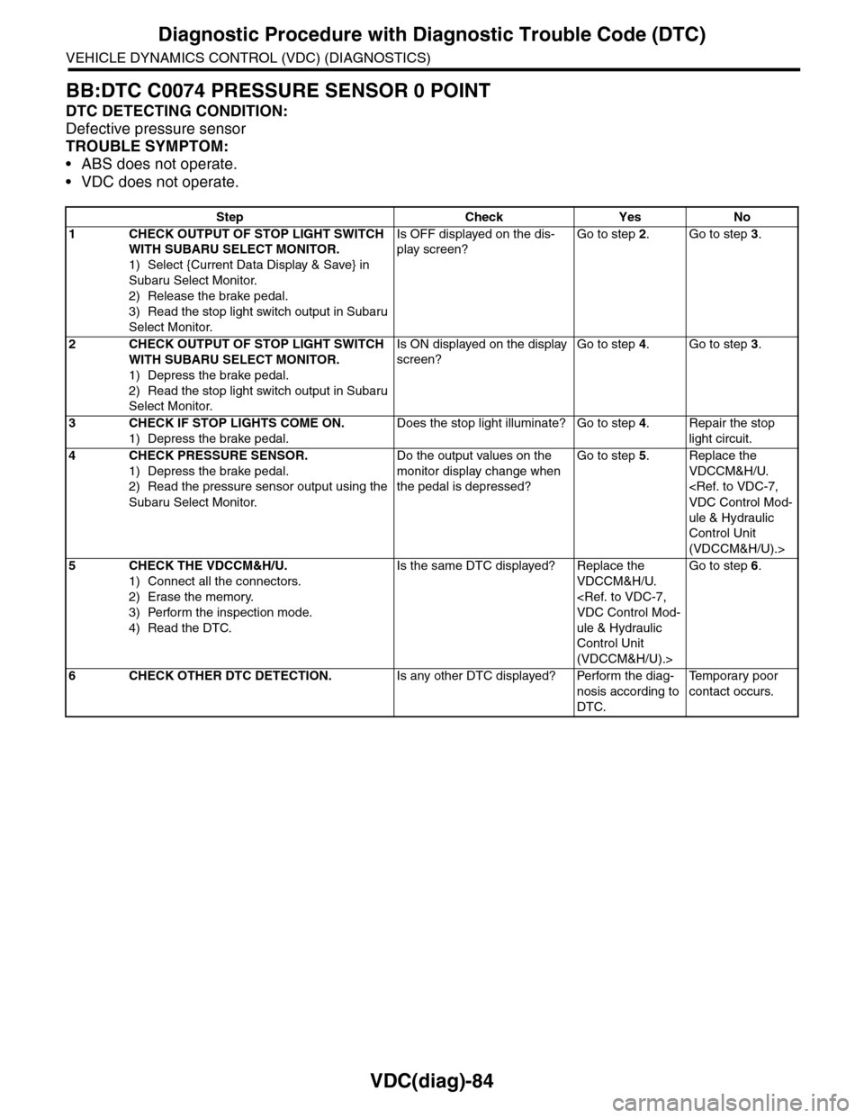
BB:DTC C0074 PRESSURE SENSOR 0 POINT
DTC DETECTING CONDITION:
Defective pressure sensor
TROUBLE SYMPTOM:
•ABS does not operate.
•VDC does not operate.
Step Check Yes No
1CHECK OUTPUT OF STOP LIGHT SWITCH
WITH SUBARU SELECT MONITOR.
1) Select {Current Data Display & Save} in
Subaru Select Monitor.
2) Release the brake pedal.
3) Read the stop light switch output in Subaru
Select Monitor.
Is OFF displayed on the dis-
play screen?
Go to step 2.Go to step 3.
2CHECK OUTPUT OF STOP LIGHT SWITCH
WITH SUBARU SELECT MONITOR.
1) Depress the brake pedal.
2) Read the stop light switch output in Subaru
Select Monitor.
Is ON displayed on the display
screen?
Go to step 4.Go to step 3.
3CHECK IF STOP LIGHTS COME ON.
1) Depress the brake pedal.
Does the stop light illuminate? Go to step 4.Repair the stop
light circuit.
4CHECK PRESSURE SENSOR.
1) Depress the brake pedal.
2) Read the pressure sensor output using the
Subaru Select Monitor.
Do the output values on the
monitor display change when
the pedal is depressed?
Go to step 5.Replace the
VDCCM&H/U.
VDC Control Mod-
ule & Hydraulic
Control Unit
(VDCCM&H/U).>
5CHECK THE VDCCM&H/U.
1) Connect all the connectors.
2) Erase the memory.
3) Perform the inspection mode.
4) Read the DTC.
Is the same DTC displayed? Replace the
VDCCM&H/U.
VDC Control Mod-
ule & Hydraulic
Control Unit
(VDCCM&H/U).>
Go to step 6.
6CHECK OTHER DTC DETECTION.Is any other DTC displayed? Perform the diag-
nosis according to
DTC.
Te m p o r a r y p o o r
contact occurs.
Page 1077 of 2453
VDC(diag)-85
Diagnostic Procedure with Diagnostic Trouble Code (DTC)
VEHICLE DYNAMICS CONTROL (VDC) (DIAGNOSTICS)
BC:DTC C0074 PRESSURE SENSOR NOISE
DTC DETECTING CONDITION:
Defective pressure sensor
TROUBLE SYMPTOM:
•ABS does not operate.
•VDC does not operate.
WIRING DIAGRAM:
MAIN SBF
SBF-6
NO.33
B310
E
E
431
VDCCM & H/U
BATTERY
GENERATOR
IGNITIONSWITCH
VDC00371
B310
1234
1516171819202122232425262728293031323334353637383940414245464344568910 11 12 13 147
Page 1078 of 2453
VDC(diag)-86
Diagnostic Procedure with Diagnostic Trouble Code (DTC)
VEHICLE DYNAMICS CONTROL (VDC) (DIAGNOSTICS)
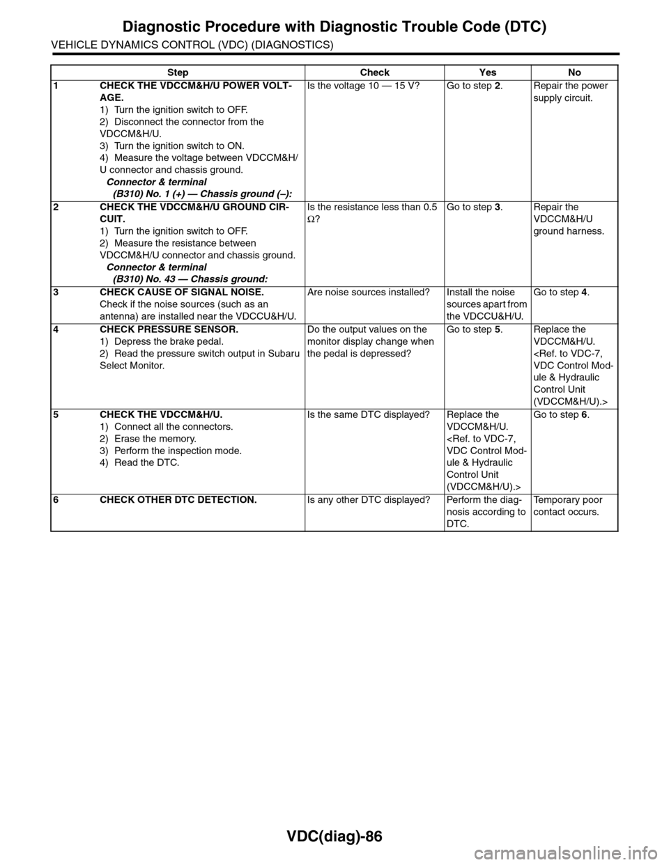
Step Check Yes No
1CHECK THE VDCCM&H/U POWER VOLT-
AGE.
1) Turn the ignition switch to OFF.
2) Disconnect the connector from the
VDCCM&H/U.
3) Turn the ignition switch to ON.
4) Measure the voltage between VDCCM&H/
U connector and chassis ground.
Connector & terminal
(B310) No. 1 (+) — Chassis ground (–):
Is the voltage 10 — 15 V? Go to step 2.Repair the power
supply circuit.
2CHECK THE VDCCM&H/U GROUND CIR-
CUIT.
1) Turn the ignition switch to OFF.
2) Measure the resistance between
VDCCM&H/U connector and chassis ground.
Connector & terminal
(B310) No. 43 — Chassis ground:
Is the resistance less than 0.5
Ω?
Go to step 3.Repair the
VDCCM&H/U
ground harness.
3CHECK CAUSE OF SIGNAL NOISE.
Check if the noise sources (such as an
antenna) are installed near the VDCCU&H/U.
Are noise sources installed? Install the noise
sources apart from
the VDCCU&H/U.
Go to step 4.
4CHECK PRESSURE SENSOR.
1) Depress the brake pedal.
2) Read the pressure switch output in Subaru
Select Monitor.
Do the output values on the
monitor display change when
the pedal is depressed?
Go to step 5.Replace the
VDCCM&H/U.
VDC Control Mod-
ule & Hydraulic
Control Unit
(VDCCM&H/U).>
5CHECK THE VDCCM&H/U.
1) Connect all the connectors.
2) Erase the memory.
3) Perform the inspection mode.
4) Read the DTC.
Is the same DTC displayed? Replace the
VDCCM&H/U.
VDC Control Mod-
ule & Hydraulic
Control Unit
(VDCCM&H/U).>
Go to step 6.
6CHECK OTHER DTC DETECTION.Is any other DTC displayed? Perform the diag-
nosis according to
DTC.
Te m p o r a r y p o o r
contact occurs.
Page 1092 of 2453
VDC-11
VDC Control Module & Hydraulic Control Unit (VDCCM&H/U)
VEHICLE DYNAMICS CONTROL (VDC)
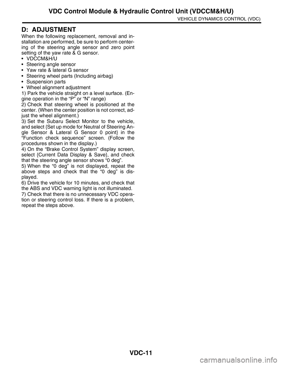
D: ADJUSTMENT
When the following replacement, removal and in-
stallation are performed, be sure to perform center-
ing of the steering angle sensor and zero point
setting of the yaw rate & G sensor.
•VDCCM&H/U
•Steering angle sensor
•Yaw rate & lateral G sensor
•Steering wheel parts (Including airbag)
•Suspension parts
•Wheel alignment adjustment
1) Park the vehicle straight on a level surface. (En-
gine operation in the “P” or “N” range)
2) Check that steering wheel is positioned at the
center. (When the center position is not correct, ad-
just the wheel alignment.)
3) Set the Subaru Select Monitor to the vehicle,
and select {Set up mode for Neutral of Steering An-
gle Sensor & Lateral G Sensor 0 point} in the
“Function check sequence” screen. (Follow the
procedures shown in the display.)
4) On the “Brake Control System” display screen,
select {Current Data Display & Save}, and check
that the steering angle sensor shows “0 deg”.
5) When the “0 deg” is not displayed, repeat the
above steps and check that the “0 deg” is dis-
played.
6) Drive the vehicle for 10 minutes, and check that
the ABS and VDC warning light is not illuminated.
7) Check that there is no unnecessary VDC opera-
tion or steering control loss. If there is a problem,
repeat the steps above.
Page 1099 of 2453
VDC-18
Yaw Rate & Lateral G Sensor
VEHICLE DYNAMICS CONTROL (VDC)
5. Yaw Rate & Lateral G Sensor
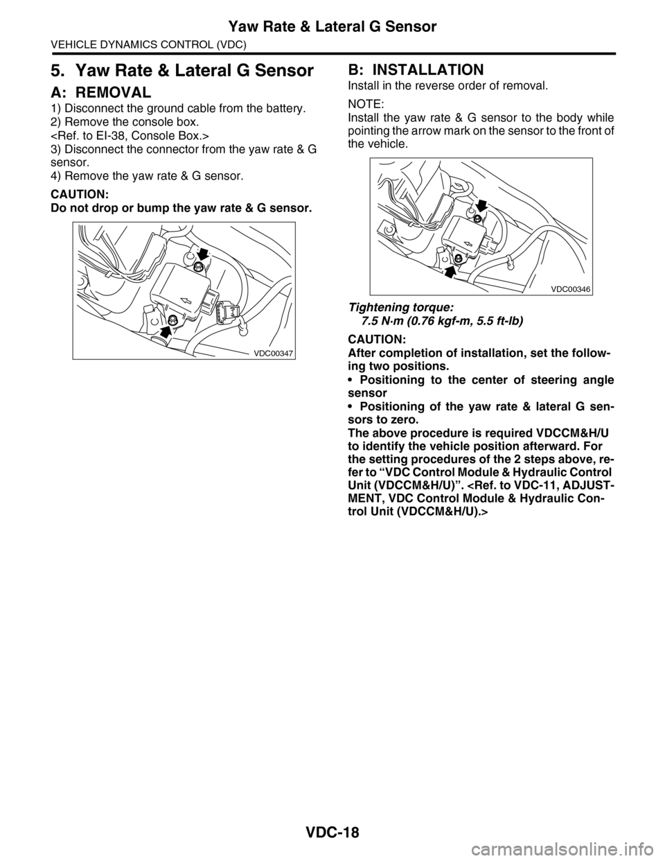
A: REMOVAL
1) Disconnect the ground cable from the battery.
2) Remove the console box.
3) Disconnect the connector from the yaw rate & G
sensor.
4) Remove the yaw rate & G sensor.
CAUTION:
Do not drop or bump the yaw rate & G sensor.
B: INSTALLATION
Install in the reverse order of removal.
NOTE:
Install the yaw rate & G sensor to the body while
pointing the arrow mark on the sensor to the front of
the vehicle.
Tightening torque:
7.5 N·m (0.76 kgf-m, 5.5 ft-lb)
CAUTION:
After completion of installation, set the follow-
ing two positions.
•Positioning to the center of steering angle
sensor
•Positioning of the yaw rate & lateral G sen-
sors to zero.
The above procedure is required VDCCM&H/U
to identify the vehicle position afterward. For
the setting procedures of the 2 steps above, re-
fer to “VDC Control Module & Hydraulic Control
Unit (VDCCM&H/U)”.
MENT, VDC Control Module & Hydraulic Con-
trol Unit (VDCCM&H/U).>
VDC00347
VDC00346
Page 1101 of 2453
VDC-20
Steering Angle Sensor
VEHICLE DYNAMICS CONTROL (VDC)
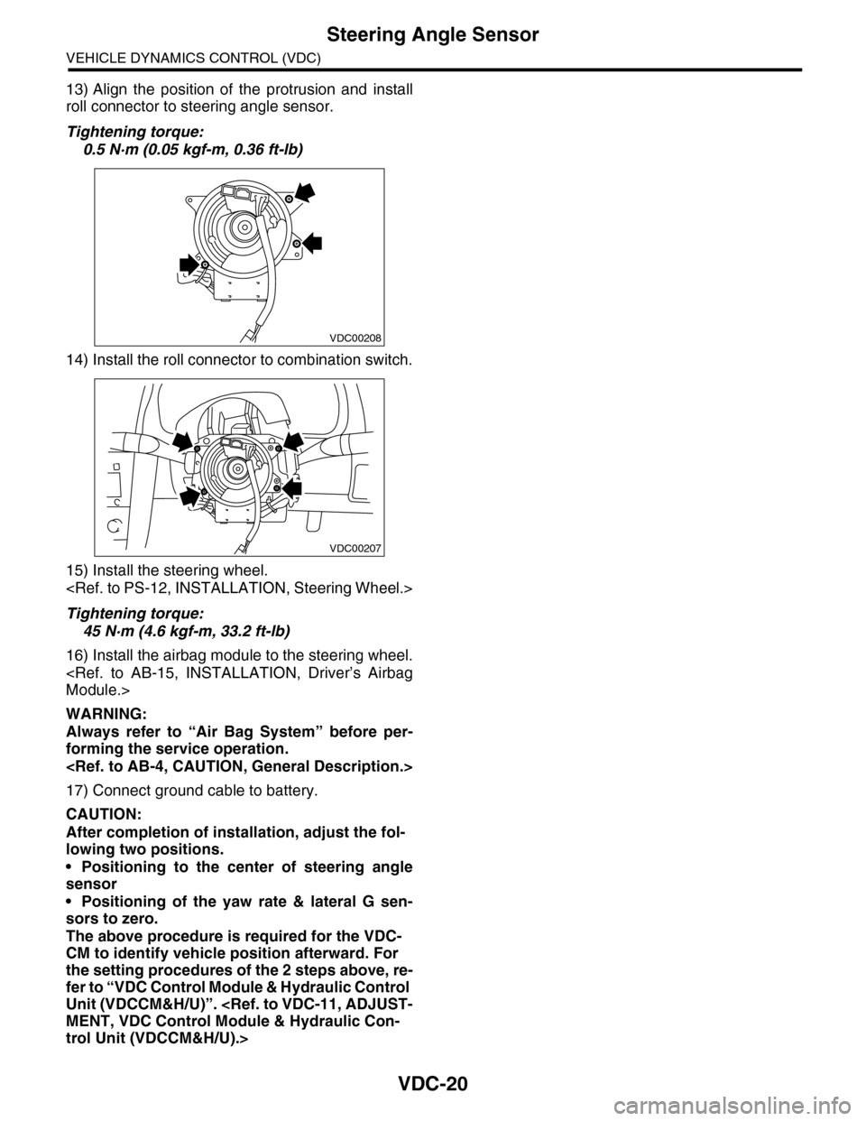
13) Align the position of the protrusion and install
roll connector to steering angle sensor.
Tightening torque:
0.5 N·m (0.05 kgf-m, 0.36 ft-lb)
14) Install the roll connector to combination switch.
15) Install the steering wheel.
Tightening torque:
45 N·m (4.6 kgf-m, 33.2 ft-lb)
16) Install the airbag module to the steering wheel.
Module.>
WARNING:
Always refer to “Air Bag System” before per-
forming the service operation.
17) Connect ground cable to battery.
CAUTION:
After completion of installation, adjust the fol-
lowing two positions.
•Positioning to the center of steering angle
sensor
•Positioning of the yaw rate & lateral G sen-
sors to zero.
The above procedure is required for the VDC-
CM to identify vehicle position afterward. For
the setting procedures of the 2 steps above, re-
fer to “VDC Control Module & Hydraulic Control
Unit (VDCCM&H/U)”.
MENT, VDC Control Module & Hydraulic Con-
trol Unit (VDCCM&H/U).>
VDC00208
VDC00207
Page 1116 of 2453
WT-10
“T–type” Tire
WHEEL AND TIRE SYSTEM
5. “T–type” Tire
A: NOTE
“T–type” tire for temporary use is equipped as a
spare tire.
CAUTION:
•Do not drive at a speed greater than 100 km/h
(62 MPH).
•For the model with tire pressure monitoring
system, the indicator light may blink when run-
ning with the “T-type” tire.
B: REPLACEMENT
Refer to Aluminum Wheels for removal and instal-
lation procedures of the “T–type”.
REMOVAL, Aluminum Wheel.>
CAUTION:
The “T–type” tire is only for temporary use. Re-
place with a conventional tire as soon as possi-
ble.
C: INSPECTION
1) Check the tire air pressure.
Specifications:
420 kPa (4.2 kg/cm2, 60 psi)
2) Take stones, glass, nails, etc. out of the tread
groove.
3) Check the tires for deformation, cracks, partial
wear, or wear.
CAUTION:
Replace the tire with a new one if defective.
Page 1120 of 2453
WT-14
General Diagnostic Table
WHEEL AND TIRE SYSTEM
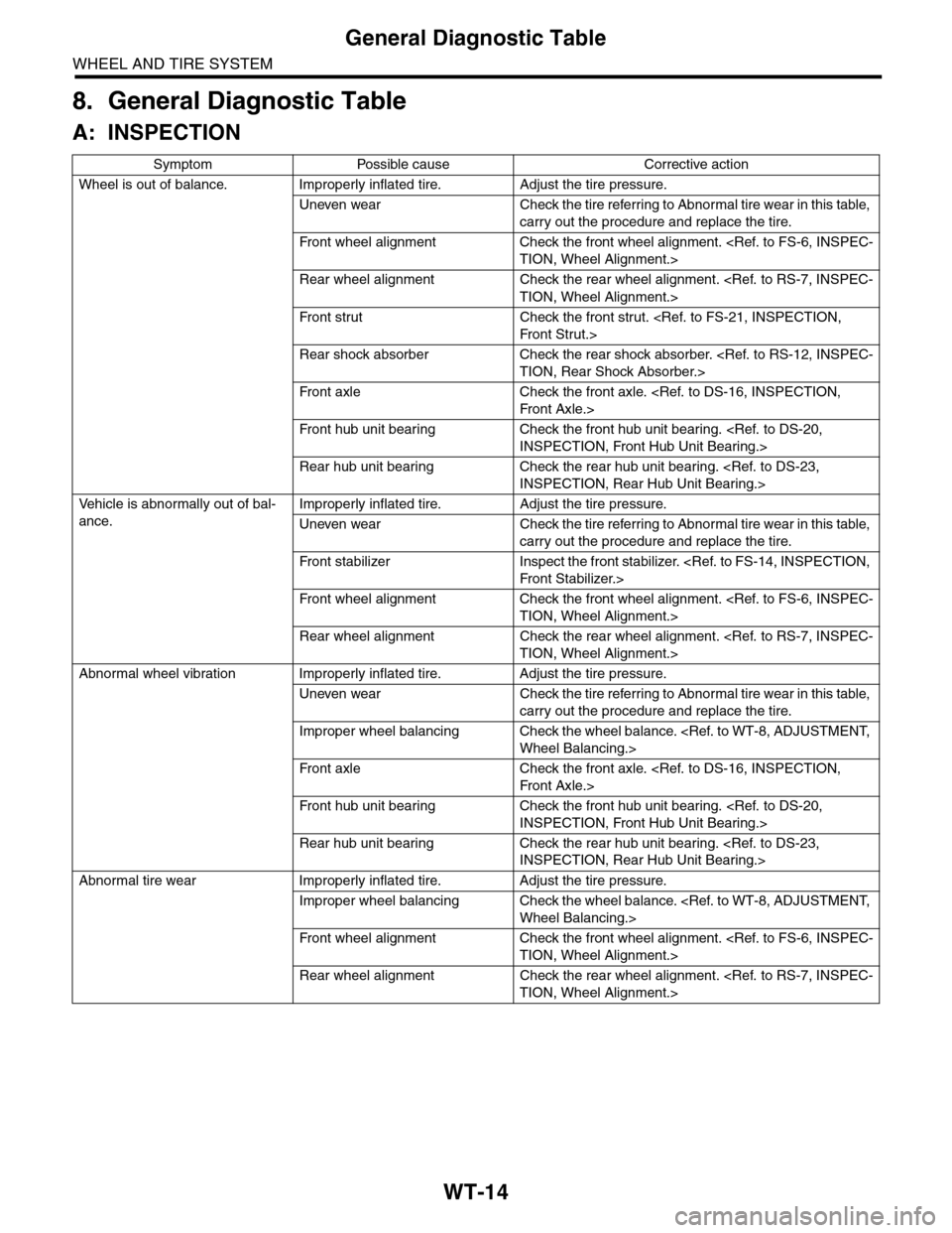
8. General Diagnostic Table
A: INSPECTION
Symptom Possible cause Corrective action
Wheel is out of balance. Improperly inflated tire. Adjust the tire pressure.
Uneven wear Check the tire referring to Abnormal tire wear in this table,
carry out the procedure and replace the tire.
Fr o nt w h ee l al ig n me nt Ch eck t he f r on t w he e l a l ig n me nt . < R ef. to F S - 6, I N S P E C -
TION, Wheel Alignment.>
Rear wheel alignment Check the rear wheel alignment.
TION, Wheel Alignment.>
Fr o nt s tr u t Ch eck th e f r o n t s tr ut .
Fr o n t S t r u t .>
Rear shock absorber Check the rear shock absorber.
TION, Rear Shock Absorber.>
Fr o nt a xl e C h eck th e f r o n t a xl e. < R e f. t o D S - 1 6, I N S P E C T IO N,
Fr o n t A x le. >
Fr o nt h ub un i t b e ar i n g Ch eck th e f r o n t h ub u ni t b e ar i n g. < Re f. t o DS - 2 0,
INSPECTION, Front Hub Unit Bearing.>
Rear hub unit bearing Check the rear hub unit bearing.
INSPECTION, Rear Hub Unit Bearing.>
Ve h i c l e i s a b n o r m a l l y o u t o f b a l -
ance.
Improperly inflated tire. Adjust the tire pressure.
Uneven wear Check the tire referring to Abnormal tire wear in this table,
carry out the procedure and replace the tire.
Fr o nt s ta b il i ze r I ns p ec t t h e f r o nt st a bi l izer. < R e f. t o F S - 14 , IN SP E C T I ON,
Fr o n t S t a bi l izer. >
Fr o nt w h ee l al ig n me nt Ch eck t he f r on t w he e l a l ig n me nt . < R ef. to F S - 6, I N S P E C -
TION, Wheel Alignment.>
Rear wheel alignment Check the rear wheel alignment.
TION, Wheel Alignment.>
Abnormal wheel vibration Improperly inflated tire. Adjust the tire pressure.
Uneven wear Check the tire referring to Abnormal tire wear in this table,
carry out the procedure and replace the tire.
Improper wheel balancing Check the wheel balance.
Wheel Balancing.>
Fr o nt a xl e C h eck th e f r o n t a xl e. < R e f. t o D S - 1 6, I N S P E C T IO N,
Fr o n t A x le. >
Fr o nt h ub un i t b e ar i n g Ch eck th e f r o n t h ub u ni t b e ar i n g. < Re f. t o DS - 2 0,
INSPECTION, Front Hub Unit Bearing.>
Rear hub unit bearing Check the rear hub unit bearing.
INSPECTION, Rear Hub Unit Bearing.>
Abnormal tire wear Improperly inflated tire. Adjust the tire pressure.
Improper wheel balancing Check the wheel balance.
Wheel Balancing.>
Fr o nt w h ee l al ig n me nt Ch eck t he f r on t w he e l a l ig n me nt . < R ef. to F S - 6, I N S P E C -
TION, Wheel Alignment.>
Rear wheel alignment Check the rear wheel alignment.
TION, Wheel Alignment.>