Page 1044 of 2453
VDC(diag)-52
Diagnostic Procedure with Diagnostic Trouble Code (DTC)
VEHICLE DYNAMICS CONTROL (VDC) (DIAGNOSTICS)
Y: DTC C0047 IMPROPER CAN COMMUNICATION
DTC DETECTING CONDITION:
CAN communication line circuit is open or shorted.
TROUBLE SYMPTOM:
•ABS does not operate.
•VDC does not operate.
Step Check Yes No
1CHECK LAN SYSTEM.
Perfor m the diagnosis for LAN system.
LAN(diag)-25, OPERATION, Read Diagnostic
Tr o u b l e C o d e ( D T C ) . >
Is there any fault in LAN sys-
tem?
Pe r for m t h e d ia g -
nosis according to
DTC for LAN sys-
tem.
Go to step 2.
2CHECK POOR CONTACT OF CONNEC-
TORS.
Is there poor contact in
VDCCM&H/U connector?
Repair the con-
nector.
Go to step 3.
3CHECK THE VDCCM&H/U.
1) Connect all the connectors.
2) Erase the memory.
3) Perform the inspection mode.
4) Read the DTC.
Is the same DTC displayed? Replace the
VDCCM&H/U.
VDC Control Mod-
ule & Hydraulic
Control Unit
(VDCCM&H/U).>
Te m p o r a r y p o o r
contact occurs.
Page 1045 of 2453
VDC(diag)-53
Diagnostic Procedure with Diagnostic Trouble Code (DTC)
VEHICLE DYNAMICS CONTROL (VDC) (DIAGNOSTICS)
Z: DTC C0051 VALVE RELAY SYSTEM OPEN LINE
DTC DETECTING CONDITION:
Defective valve relay
TROUBLE SYMPTOM:
•ABS does not operate.
•EBD does not operate.
•VDC does not operate.
WIRING DIAGRAM:
B310
E
4443
VDCCM & H/U
1
PUMP MOTOR
M
FL INLET
MAIN SBF
SBF-6
NO.1
NO.33
E
BATTERY
IGNITIONSWITCH
SOLENOID VALVE
FR INLETRL INLETRR INLETFL OUTLETFR OUTLETRL OUTLETRR OUTLET
PRIMARY NEAR VALVESECONDARY NEAR VALVEVALVERELAY
VDC00372
B310
1234
1516171819202122232425262728293031323334353637383940414245464344568910 11 12 13 147
Page 1046 of 2453

VDC(diag)-54
Diagnostic Procedure with Diagnostic Trouble Code (DTC)
VEHICLE DYNAMICS CONTROL (VDC) (DIAGNOSTICS)
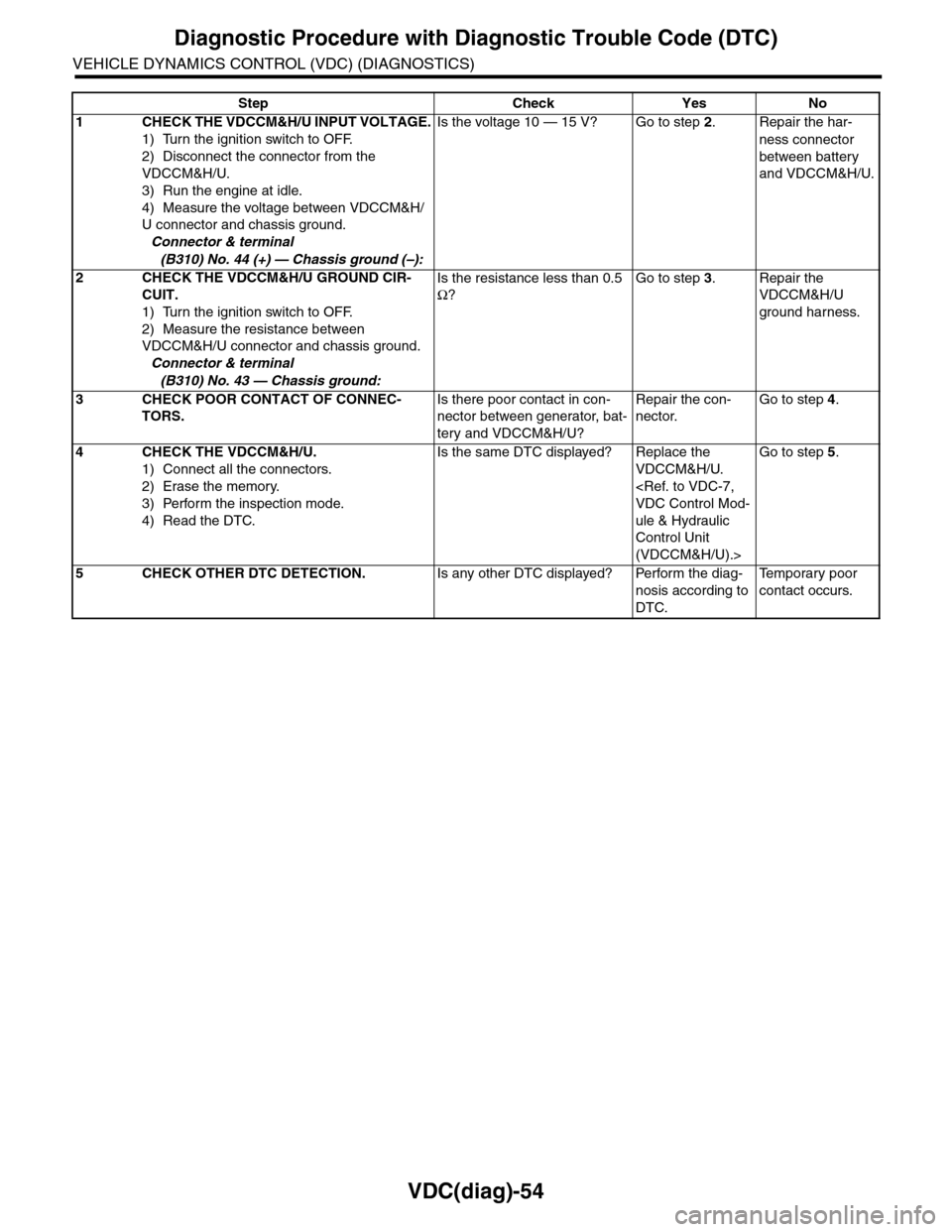
Step Check Yes No
1CHECK THE VDCCM&H/U INPUT VOLTAGE.
1) Turn the ignition switch to OFF.
2) Disconnect the connector from the
VDCCM&H/U.
3) Run the engine at idle.
4) Measure the voltage between VDCCM&H/
U connector and chassis ground.
Connector & terminal
(B310) No. 44 (+) — Chassis ground (–):
Is the voltage 10 — 15 V? Go to step 2.Repair the har-
ness connector
between battery
and VDCCM&H/U.
2CHECK THE VDCCM&H/U GROUND CIR-
CUIT.
1) Turn the ignition switch to OFF.
2) Measure the resistance between
VDCCM&H/U connector and chassis ground.
Connector & terminal
(B310) No. 43 — Chassis ground:
Is the resistance less than 0.5
Ω?
Go to step 3.Repair the
VDCCM&H/U
ground harness.
3CHECK POOR CONTACT OF CONNEC-
TORS.
Is there poor contact in con-
nector between generator, bat-
tery and VDCCM&H/U?
Repair the con-
nector.
Go to step 4.
4CHECK THE VDCCM&H/U.
1) Connect all the connectors.
2) Erase the memory.
3) Perform the inspection mode.
4) Read the DTC.
Is the same DTC displayed? Replace the
VDCCM&H/U.
VDC Control Mod-
ule & Hydraulic
Control Unit
(VDCCM&H/U).>
Go to step 5.
5CHECK OTHER DTC DETECTION.Is any other DTC displayed? Perform the diag-
nosis according to
DTC.
Te m p o r a r y p o o r
contact occurs.
Page 1047 of 2453
VDC(diag)-55
Diagnostic Procedure with Diagnostic Trouble Code (DTC)
VEHICLE DYNAMICS CONTROL (VDC) (DIAGNOSTICS)
AA:DTC C0051 VALVE RELAY SYSTEM SHORT
DTC DETECTING CONDITION:
Defective valve relay
TROUBLE SYMPTOM:
•ABS does not operate.
•VDC does not operate.
•EBD may not operate.
WIRING DIAGRAM:
B310
E
4443
VDCCM & H/U
1
PUMP MOTOR
M
FL INLET
MAIN SBF
SBF-6
NO.1
NO.33
E
BATTERY
IGNITIONSWITCH
SOLENOID VALVE
FR INLETRL INLETRR INLETFL OUTLETFR OUTLETRL OUTLETRR OUTLET
PRIMARY NEAR VALVESECONDARY NEAR VALVEVALVERELAY
VDC00372
B310
1234
1516171819202122232425262728293031323334353637383940414245464344568910 11 12 13 147
Page 1048 of 2453

VDC(diag)-56
Diagnostic Procedure with Diagnostic Trouble Code (DTC)
VEHICLE DYNAMICS CONTROL (VDC) (DIAGNOSTICS)
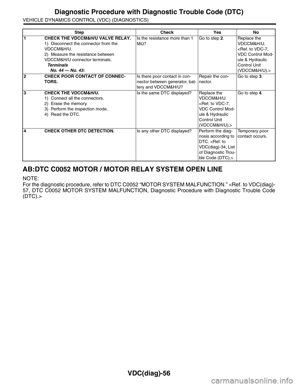
AB:DTC C0052 MOTOR / MOTOR RELAY SYSTEM OPEN LINE
NOTE:
For the diagnostic procedure, refer to DTC C0052 “MOTOR SYSTEM MALFUNCTION.”
57, DTC C0052 MOTOR SYSTEM MALFUNCTION, Diagnostic Procedure with Diagnostic Trouble Code
(DTC).>
Step Check Yes No
1CHECK THE VDCCM&H/U VALVE RELAY.
1) Disconnect the connector from the
VDCCM&H/U.
2) Measure the resistance between
VDCCM&H/U connector terminals.
Te r m i n a l s
No. 44 — No. 43:
Is the resistance more than 1
MΩ?
Go to step 2.Replace the
VDCCM&H/U.
VDC Control Mod-
ule & Hydraulic
Control Unit
(VDCCM&H/U).>
2CHECK POOR CONTACT OF CONNEC-
TORS.
Is there poor contact in con-
nector between generator, bat-
tery and VDCCM&H/U?
Repair the con-
nector.
Go to step 3.
3CHECK THE VDCCM&H/U.
1) Connect all the connectors.
2) Erase the memory.
3) Perform the inspection mode.
4) Read the DTC.
Is the same DTC displayed? Replace the
VDCCM&H/U.
VDC Control Mod-
ule & Hydraulic
Control Unit
(VDCCM&H/U).>
Go to step 4.
4CHECK OTHER DTC DETECTION.Is any other DTC displayed? Perform the diag-
nosis according to
DTC.
VDC(diag)-34, List
of Diagnostic Trou-
ble Code (DTC).>
Te m p o r a r y p o o r
contact occurs.
Page 1049 of 2453
VDC(diag)-57
Diagnostic Procedure with Diagnostic Trouble Code (DTC)
VEHICLE DYNAMICS CONTROL (VDC) (DIAGNOSTICS)
AC:DTC C0052 MOTOR SYSTEM MALFUNCTION
DTC DETECTING CONDITION:
•Defective motor and motor relay
•Defective harness connector
TROUBLE SYMPTOM:
•ABS does not operate.
•VDC does not operate.
•EBD may not operate.
WIRING DIAGRAM:
B310
B423
VC1
B423
VC1
VC2
E
246
2314
B310 VDCCM & H/U
1234
1516171819202122232425262728293031323334353637383940414245464344568910 11 12 13 147
VDC00373
1314
1211
421453031
E
MAIN SBF
SBF-6
NO.33
E
BATTERY
IGNITIONSWITCH
MOTORRELAY
RELAY BOXFAILSAFERELAY
B423
34561278
VC2
12345
678910121311
14
SBF-1
M
96
108
5
Page 1050 of 2453

VDC(diag)-58
Diagnostic Procedure with Diagnostic Trouble Code (DTC)
VEHICLE DYNAMICS CONTROL (VDC) (DIAGNOSTICS)
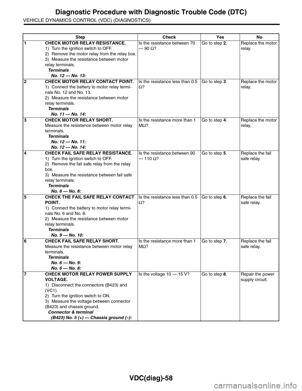
Step Check Yes No
1CHECK MOTOR RELAY RESISTANCE.
1) Turn the ignition switch to OFF.
2) Remove the motor relay from the relay box.
3) Measure the resistance between motor
relay terminals.
Te r m i n a l s
No. 12 — No. 13:
Is the resistance between 70
— 90 Ω?
Go to step 2.Replace the motor
relay.
2CHECK MOTOR RELAY CONTACT POINT.
1) Connect the battery to motor relay termi-
nals No. 12 and No. 13.
2) Measure the resistance between motor
relay terminals.
Te r m i n a l s
No. 11 — No. 14:
Is the resistance less than 0.5
Ω?
Go to step 3.Replace the motor
relay.
3CHECK MOTOR RELAY SHORT.
Measure the resistance between motor relay
terminals.
Te r m i n a l s
No. 12 — No. 11:
No. 12 — No. 14:
Is the resistance more than 1
MΩ?
Go to step 4.Replace the motor
relay.
4CHECK FAIL SAFE RELAY RESISTANCE.
1) Turn the ignition switch to OFF.
2) Remove the fail safe relay from the relay
box.
3) Measure the resistance between fail safe
relay terminals.
Te r m i n a l s
No. 6 — No. 8:
Is the resistance between 90
— 110 Ω?
Go to step 5.Replace the fail
safe relay.
5CHECK THE FAIL SAFE RELAY CONTACT
POINT.
1) Connect the battery to motor relay termi-
nals No. 6 and No. 8.
2) Measure the resistance between motor
relay terminals.
Te r m i n a l s
No. 9 — No. 10:
Is the resistance less than 0.5
Ω?
Go to step 6.Replace the fail
safe relay.
6 CHECK FAIL SAFE RELAY SHORT.
Measure the resistance between motor relay
terminals.
Te r m i n a l s
No. 6 — No. 9:
No. 6 — No. 8:
Is the resistance more than 1
MΩ?
Go to step 7.Replace the fail
safe relay.
7CHECK MOTOR RELAY POWER SUPPLY
VOLTAGE.
1) Disconnect the connectors (B423) and
(VC1).
2) Turn the ignition switch to ON.
3) Measure the voltage between connector
(B423) and chassis ground.
Connector & terminal
(B423) No. 5 (+) — Chassis ground (–):
Is the voltage 10 — 15 V? Go to step 8.Repair the power
supply circuit.
Page 1051 of 2453

VDC(diag)-59
Diagnostic Procedure with Diagnostic Trouble Code (DTC)
VEHICLE DYNAMICS CONTROL (VDC) (DIAGNOSTICS)
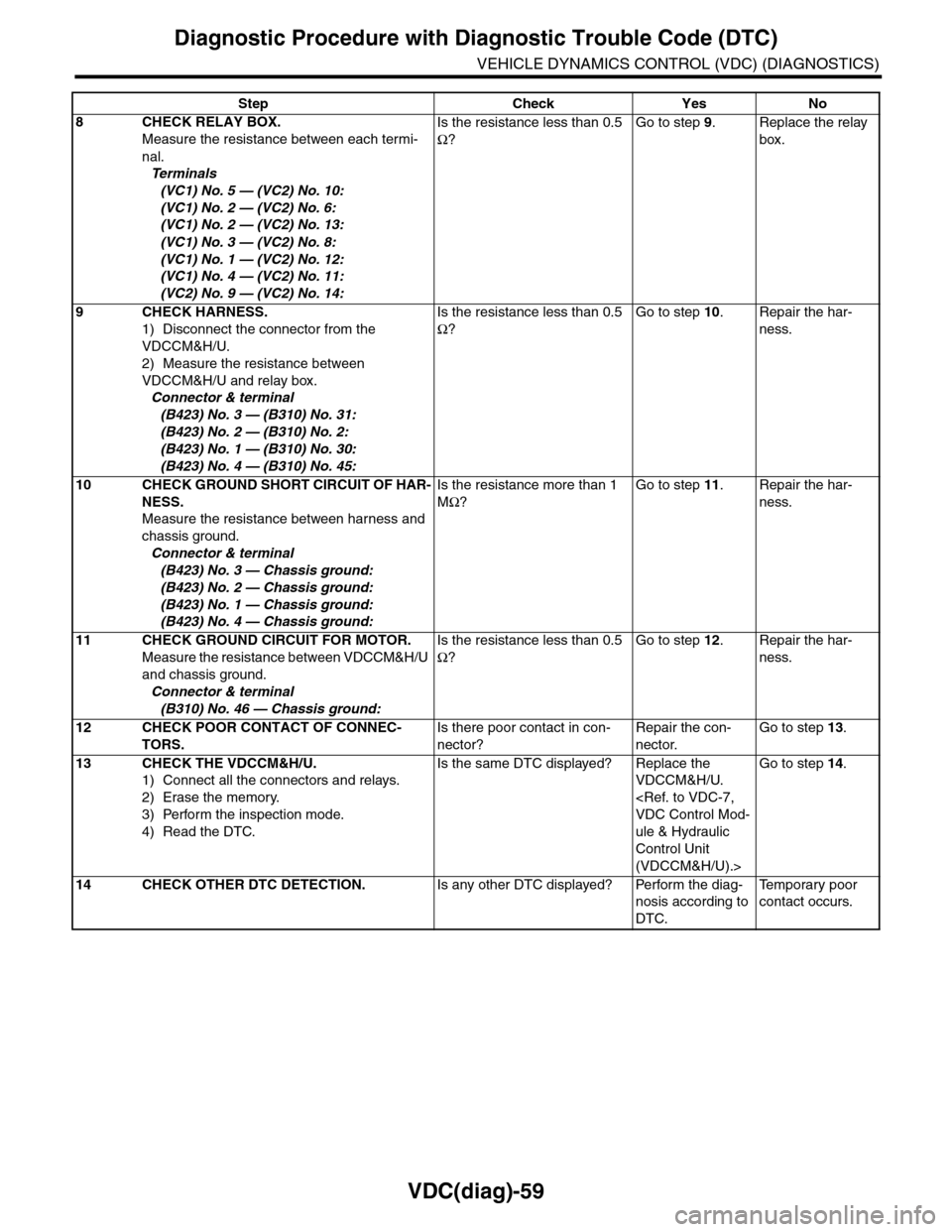
8CHECK RELAY BOX.
Measure the resistance between each termi-
nal.
Te r m i n a l s
(VC1) No. 5 — (VC2) No. 10:
(VC1) No. 2 — (VC2) No. 6:
(VC1) No. 2 — (VC2) No. 13:
(VC1) No. 3 — (VC2) No. 8:
(VC1) No. 1 — (VC2) No. 12:
(VC1) No. 4 — (VC2) No. 11:
(VC2) No. 9 — (VC2) No. 14:
Is the resistance less than 0.5
Ω?
Go to step 9.Replace the relay
box.
9CHECK HARNESS.
1) Disconnect the connector from the
VDCCM&H/U.
2) Measure the resistance between
VDCCM&H/U and relay box.
Connector & terminal
(B423) No. 3 — (B310) No. 31:
(B423) No. 2 — (B310) No. 2:
(B423) No. 1 — (B310) No. 30:
(B423) No. 4 — (B310) No. 45:
Is the resistance less than 0.5
Ω?
Go to step 10.Repair the har-
ness.
10 CHECK GROUND SHORT CIRCUIT OF HAR-
NESS.
Measure the resistance between harness and
chassis ground.
Connector & terminal
(B423) No. 3 — Chassis ground:
(B423) No. 2 — Chassis ground:
(B423) No. 1 — Chassis ground:
(B423) No. 4 — Chassis ground:
Is the resistance more than 1
MΩ?
Go to step 11.Repair the har-
ness.
11 CHECK GROUND CIRCUIT FOR MOTOR.
Measure the resistance between VDCCM&H/U
and chassis ground.
Connector & terminal
(B310) No. 46 — Chassis ground:
Is the resistance less than 0.5
Ω?
Go to step 12.Repair the har-
ness.
12 CHECK POOR CONTACT OF CONNEC-
TORS.
Is there poor contact in con-
nector?
Repair the con-
nector.
Go to step 13.
13 CHECK THE VDCCM&H/U.
1) Connect all the connectors and relays.
2) Erase the memory.
3) Perform the inspection mode.
4) Read the DTC.
Is the same DTC displayed? Replace the
VDCCM&H/U.
VDC Control Mod-
ule & Hydraulic
Control Unit
(VDCCM&H/U).>
Go to step 14.
14 CHECK OTHER DTC DETECTION.Is any other DTC displayed? Perform the diag-
nosis according to
DTC.
Te m p o r a r y p o o r
contact occurs.
Step Check Yes No