2009 SUBARU TRIBECA ac 25 procedure
[x] Cancel search: ac 25 procedurePage 995 of 2453

VDC(diag)-3
Basic Diagnostic Procedure
VEHICLE DYNAMICS CONTROL (VDC) (DIAGNOSTICS)
4PERFORM THE DIAGNOSIS.
1) Refer to “List of Diagnostic Trouble Code
(DTC)”.
NOTE:For the DTC list, refer to “List of Diagnostic
Trouble Code (DTC)”.
2) Correct the cause of trouble.
3) Perform the clear memory mode.
Mode.>
4) Perform the inspection mode.
Mode.>
5) Read the DTC.
(DTC).>
Is DTC displayed? Repeat step 4 until
DTC is not shown.
Finish the diagno-
sis.
Step Check Yes No
Page 1008 of 2453
VDC(diag)-16
Subaru Select Monitor
VEHICLE DYNAMICS CONTROL (VDC) (DIAGNOSTICS)
6. Subaru Select Monitor
A: OPERATION
1. READ DIAGNOSTIC TROUBLE CODE
(DTC)
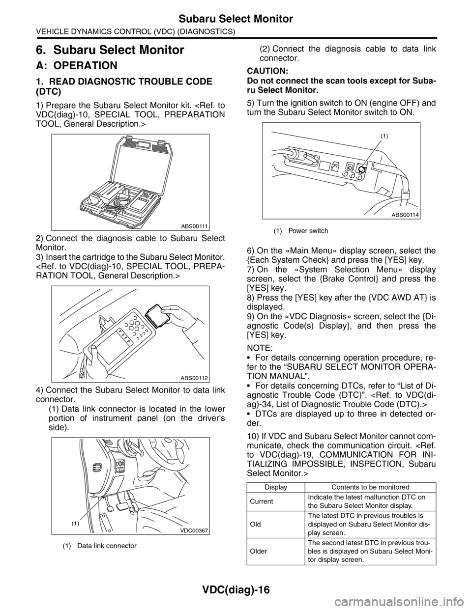
1) Prepare the Subaru Select Monitor kit.
TOOL, General Description.>
2) Connect the diagnosis cable to Subaru Select
Monitor.
3) Insert the cartridge to the Subaru Select Monitor.
4) Connect the Subaru Select Monitor to data link
connector.
(1) Data link connector is located in the lower
portion of instrument panel (on the driver's
side).
(2) Connect the diagnosis cable to data link
connector.
CAUTION:
Do not connect the scan tools except for Suba-
ru Select Monitor.
5) Turn the ignition switch to ON (engine OFF) and
turn the Subaru Select Monitor switch to ON.
6) On the «Main Menu» display screen, select the
{Each System Check} and press the [YES] key.
7) On the «System Selection Menu» display
screen, select the {Brake Control} and press the
[YES] key.
8) Press the [YES] key after the {VDC AWD AT} is
displayed.
9) On the «VDC Diagnosis» screen, select the {Di-
agnostic Code(s) Display}, and then press the
[YES] key.
NOTE:
•For details concerning operation procedure, re-
fer to the “SUBARU SELECT MONITOR OPERA-
TION MANUAL”.
•For details concerning DTCs, refer to “List of Di-
agnostic Trouble Code (DTC)”.
•DTCs are displayed up to three in detected or-
der.
10) If VDC and Subaru Select Monitor cannot com-
municate, check the communication circuit.
TIALIZING IMPOSSIBLE, INSPECTION, Subaru
Select Monitor.>
(1) Data link connector
ABS00111
ABS00112
VDC00367(1)
(1) Power switch
Display Contents to be monitored
CurrentIndicate the latest malfunction DTC on
the Subaru Select Monitor display.
Old
The latest DTC in previous troubles is
displayed on Subaru Select Monitor dis-
play screen.
Older
The second latest DTC in previous trou-
bles is displayed on Subaru Select Moni-
tor display screen.
ABS00114
(1)
Page 1009 of 2453
![SUBARU TRIBECA 2009 1.G Service Workshop Manual VDC(diag)-17
Subaru Select Monitor
VEHICLE DYNAMICS CONTROL (VDC) (DIAGNOSTICS)
2. READ CURRENT DATA
1) On the «Main Menu» display screen, select the {Each System Check} and press the [YES] key.
2) SUBARU TRIBECA 2009 1.G Service Workshop Manual VDC(diag)-17
Subaru Select Monitor
VEHICLE DYNAMICS CONTROL (VDC) (DIAGNOSTICS)
2. READ CURRENT DATA
1) On the «Main Menu» display screen, select the {Each System Check} and press the [YES] key.
2)](/manual-img/17/7322/w960_7322-1008.png)
VDC(diag)-17
Subaru Select Monitor
VEHICLE DYNAMICS CONTROL (VDC) (DIAGNOSTICS)
2. READ CURRENT DATA
1) On the «Main Menu» display screen, select the {Each System Check} and press the [YES] key.
2) On the «System Selection Menu» display screen, select the {Brake Control} and press the [YES] key.
3) Press the [YES] key after {VDC AWD AT} is displayed.
4) On the «Brake Control Diagnosis» display screen, select the {Current Data Display/Save}, and then press
the [YES] key.
5) On the «Display Menu» screen, select the data display method and press the [YES] key.
6) Using a scroll key, scroll the display screen up or down until necessary data is shown.
•A list of the support data is shown in the following table.
NOTE:
For details concerning operation procedure, refer to the “SUBARU SELECT MONITOR OPERATION MAN-
UAL”.
Display Contents to be monitored Unit of measure
FR Wheel SpeedWheel speed detected by front ABS wheel speed sensor RH is dis-
played.km/h or MPH
FL Wheel SpeedWheel speed detected by front ABS wheel speed sensor LH is dis-
played.km/h or MPH
RR Wheel SpeedWheel speed detected by rear ABS wheel speed sensor RH is dis-
played.km/h or MPH
RL Wheel SpeedWheel speed detected by rear ABS wheel speed sensor LH is dis-
played.km/h or MPH
Fr o nt / Re ar G S e ns o r Ve h ic le f r on t / re a r ac ce le ra t io n d e te c te d by G se n so r is d i sp layed .m/s2
Lateral G Sensor Vehicle lateral acceleration detected by G sensor is displayed.m/s2
IG power supply voltage Voltage supplied to VDCCM&H/U is displayed. V
Steering Angle Sensor Steering angle detected by steering angle sensor is displayed. deg
Ya w R a t e S e n s o r V e h i c l e a n g u l a r s p e e d d e t e c t e d b y y a w r a t e s e n s o r i s d i s p l a y e d . d e g / s
Pressure Sensor Brake fluid pressure detected by pressure sensor is displayed. bar
ABS Control Flag ABS control condition is displayed. ON or OFF
EBD Control Flag EBD control condition is displayed. ON or OFF
Brake Switch Brake ON/OFF is displayed. ON or OFF
ABS Warning Light ON operation of the ABS warning light is displayed. ON or OFF
EBD Warning Light ON operation of the EBD warning light is displayed. ON or OFF
Motor Relay Signal Motor relay operation signal is displayed. ON or OFF
Motor Relay Monitor Motor relay monitor signal is displayed. ON or OFF
TCS Control Flag TCS control condition is displayed. ON or OFF
Va l ve R e l ay S i g n a l Va l v e r e l ay o p e r a t i o n s i g n a l i s d i s p l ay e d . O N o r O F F
VDC Control Flag VDC control condition is displayed. ON or OFF
VDC Warning Light ON operation of the VDC warning light is displayed. ON or OFF
OFF Light ON/OFF condition of TCS OFF indicator light is displayed. ON or OFF
E/G Control Prohibited Flag Engine control command signal is displayed. 1 or 0
OFF Switch Signal Operation condition of TCS OFF switch is displayed. ON or OFF
Motor Fail Safe Relay Drive
SignalMotor fail safe relay drive signal is displayed. ON or OFF
Page 1010 of 2453
![SUBARU TRIBECA 2009 1.G Service Workshop Manual VDC(diag)-18
Subaru Select Monitor
VEHICLE DYNAMICS CONTROL (VDC) (DIAGNOSTICS)
3. CLEAR MEMORY MODE
1) On the «Main Menu», select the {2. Each Sys-
tem Check} and press the [YES] key.
2) On SUBARU TRIBECA 2009 1.G Service Workshop Manual VDC(diag)-18
Subaru Select Monitor
VEHICLE DYNAMICS CONTROL (VDC) (DIAGNOSTICS)
3. CLEAR MEMORY MODE
1) On the «Main Menu», select the {2. Each Sys-
tem Check} and press the [YES] key.
2) On](/manual-img/17/7322/w960_7322-1009.png)
VDC(diag)-18
Subaru Select Monitor
VEHICLE DYNAMICS CONTROL (VDC) (DIAGNOSTICS)
3. CLEAR MEMORY MODE
1) On the «Main Menu», select the {2. Each Sys-
tem Check} and press the [YES] key.
2) On the «System Selection Menu» display
screen, select the {Brake Control} and press the
[YES] key.
3) Press the [YES] key after {VDC AWD AT} is dis-
played.
4) On the «Brake Control Diagnosis» display
screen, select the {Memory Clear} and press the
[YES] key.
5) When “Done” and “Turn ignition switch OFF” are
shown on the display screen, turn the Subaru Se-
lect Monitor and ignition switch to OFF.
NOTE:
For details concerning operation procedure, refer
to the “SUBARU SELECT MONITOR OPERATION
MANUAL”.
4. SEQUENCE CONTROL
5. FREEZE FRAME DATA
NOTE:
•Data stored at the time of trouble occurrence is
shown on display.
•Each time trouble occurs, the latest information
is stored in the freeze frame data in memory.
Display Contents to be monitored
Clear memory? DTC deleting function
Display Contents to be monitoredReference tar-
get
ABS
sequence
control
Operate the valve and
pump motor continuously
to perform the ABS
sequence control.
Sequence Con-
trol.>
VDC
sequence
control
Operate the valve and
pump motor continuously
to perform the VDC
sequence control.
Sequence Con-
trol.>
Display Contents to be monitored
IG CounterNumber of times ignition switch turned to
ON is displayed.
DTC The recorded failure code is displayed.
FR Wheel
Speed
Wheel speed detected by front ABS
wheel speed sensor RH is displayed in
km/h or MPH.
FL Wheel Speed
Wheel speed detected by front ABS
wheel speed sensor LH is displayed in
km/h or MPH.
RR Wheel
Speed
Wheel speed detected by rear ABS
wheel speed sensor RH is displayed in
km/h or MPH.
RL Wheel
Speed
Wheel speed detected by rear ABS
wheel speed sensor LH is displayed in
km/h or MPH.
Ve h i c l e S p e e dVe h i c l e s p e e d c a l c u l a t e d b y V D C c o n t r o l
module is displayed.
G Sensor First
ShaftThe sensor value for a 45° angle crossed
2 axis G sensor is displayed.G Sensor Sec-
ond Shaft
Ya w R a t e S e n -
sor
Ve h i c l e a n g u l a r s p e e d d e t e c t e d b y y a w
rate sensor is displayed.
IG power supply
voltage
Vo l t a g e s u p p l i e d t o V D C c o n t r o l m o d u l e
is displayed.
Steering Angle
Sensor
Steering angle detected by steering
angle sensor is displayed.
Pressure sen-
sor output
Brake fluid pressure detected by pres-
sure sensor is displayed.
Engine SpeedEngine speed on malfunction occur-
rence is displayed.
Acceleration
Opening AngleAcceleration opening is displayed.
Gear positionGear position on malfunction occurrence
is displayed.
Steering Angle
Sensor Malfunc-
tion Code
The recorded steering angle sensor fail-
ure code is displayed?
ABS Control
FlagABS control condition is displayed.
EBD Control
FlagEBD control condition is displayed.
Brake Switch Brake ON/OFF is displayed.
TCS Control
FlagTCS control condition is displayed.
VDC Control
FlagVDC control condition is displayed.
E/G Control Flag
Absolute angle
recognition flag
Whether the absolute angle was deter-
mined is displayed.
OFF Switch Sig-
nal
Operation condition of TCS OFF switch
is displayed.
Page 1014 of 2453
VDC(diag)-22
Read Diagnostic Trouble Code (DTC)
VEHICLE DYNAMICS CONTROL (VDC) (DIAGNOSTICS)
7. Read Diagnostic Trouble
Code (DTC)
A: OPERATION
For details concerning DTC reading procedure, re-
fer to “Subaru Select Monitor”.
Page 1015 of 2453
VDC(diag)-23
Inspection Mode
VEHICLE DYNAMICS CONTROL (VDC) (DIAGNOSTICS)
8. Inspection Mode
A: PROCEDURE
Reproduce the malfunction occurrence condition
as possible.
Drive the vehicle at least ten minutes.
NOTE:
Make sure the vehicle is not dragged to one side
under usual driving condition.
Page 1026 of 2453
VDC(diag)-34
List of Diagnostic Trouble Code (DTC)
VEHICLE DYNAMICS CONTROL (VDC) (DIAGNOSTICS)
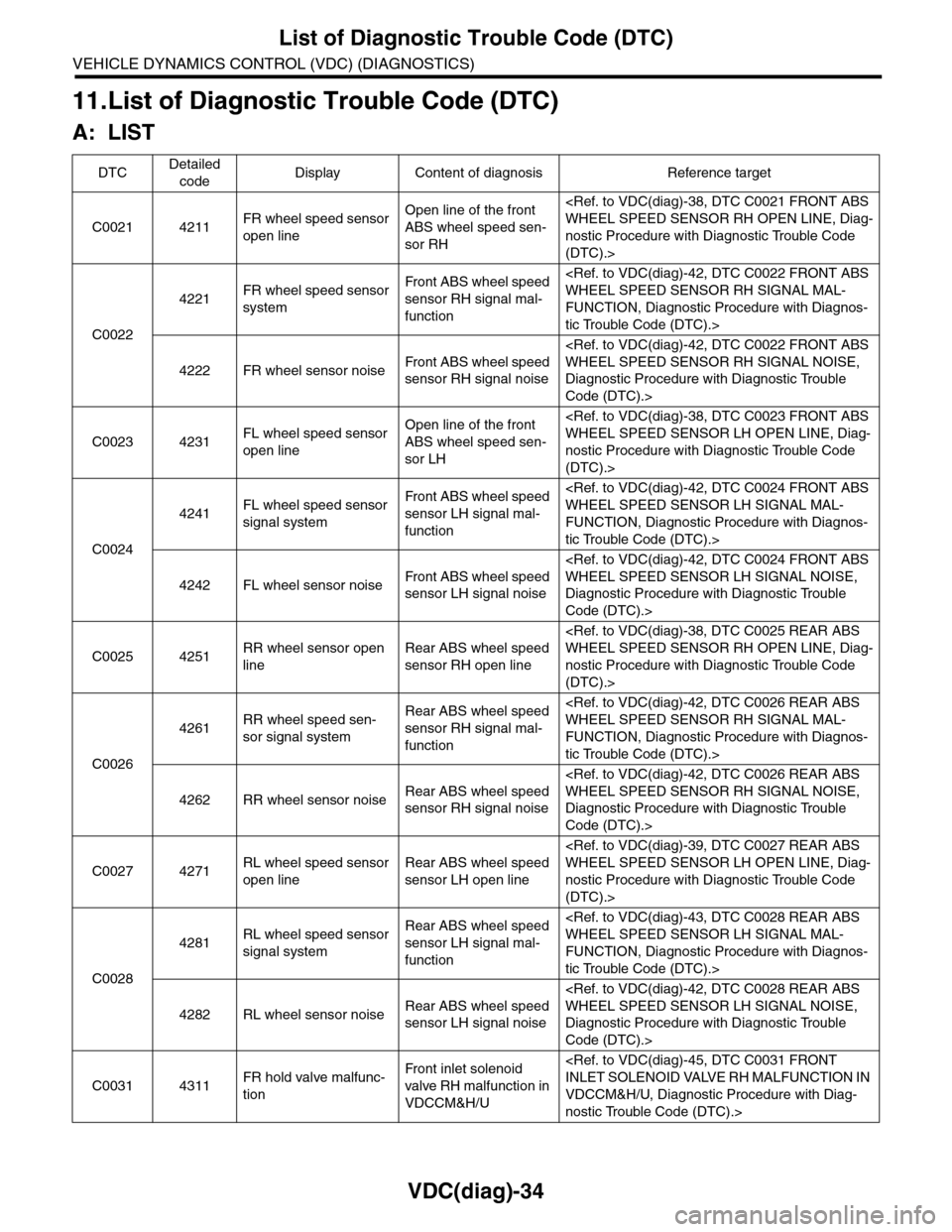
11.List of Diagnostic Trouble Code (DTC)
A: LIST
DTCDetailed
codeDisplay Content of diagnosis Reference target
C0021 4211FR wheel speed sensor
open line
Open line of the front
ABS wheel speed sen-
sor RH
nostic Procedure with Diagnostic Trouble Code
(DTC).>
C0022
4221FR wheel speed sensor
system
Fr o nt A B S w h e el sp e ed
sensor RH signal mal-
function
FUNCTION, Diagnostic Procedure with Diagnos-
tic Trouble Code (DTC).>
4222 FR wheel sensor noiseFr o nt A B S w h e el sp e ed
sensor RH signal noise
Diagnostic Procedure with Diagnostic Trouble
Code (DTC).>
C0023 4231FL wheel speed sensor
open line
Open line of the front
ABS wheel speed sen-
sor LH
nostic Procedure with Diagnostic Trouble Code
(DTC).>
C0024
4241FL wheel speed sensor
signal system
Fr o nt A B S w h e el sp e ed
sensor LH signal mal-
function
FUNCTION, Diagnostic Procedure with Diagnos-
tic Trouble Code (DTC).>
4242 FL wheel sensor noiseFr o nt A B S w h e el sp e ed
sensor LH signal noise
Diagnostic Procedure with Diagnostic Trouble
Code (DTC).>
C0025 4251RR wheel sensor open
line
Rear ABS wheel speed
sensor RH open line
nostic Procedure with Diagnostic Trouble Code
(DTC).>
C0026
4261RR wheel speed sen-
sor signal system
Rear ABS wheel speed
sensor RH signal mal-
function
FUNCTION, Diagnostic Procedure with Diagnos-
tic Trouble Code (DTC).>
4262 RR wheel sensor noiseRear ABS wheel speed
sensor RH signal noise
Diagnostic Procedure with Diagnostic Trouble
Code (DTC).>
C0027 4271RL wheel speed sensor
open line
Rear ABS wheel speed
sensor LH open line
nostic Procedure with Diagnostic Trouble Code
(DTC).>
C0028
4281RL wheel speed sensor
signal system
Rear ABS wheel speed
sensor LH signal mal-
function
FUNCTION, Diagnostic Procedure with Diagnos-
tic Trouble Code (DTC).>
4282 RL wheel sensor noiseRear ABS wheel speed
sensor LH signal noise
Diagnostic Procedure with Diagnostic Trouble
Code (DTC).>
C0031 4311FR hold valve malfunc-
tion
Fr o nt i nl e t s ol e no i d
valve RH malfunction in
VDCCM&H/U
VDCCM&H/U, Diagnostic Procedure with Diag-
nostic Trouble Code (DTC).>
Page 1027 of 2453
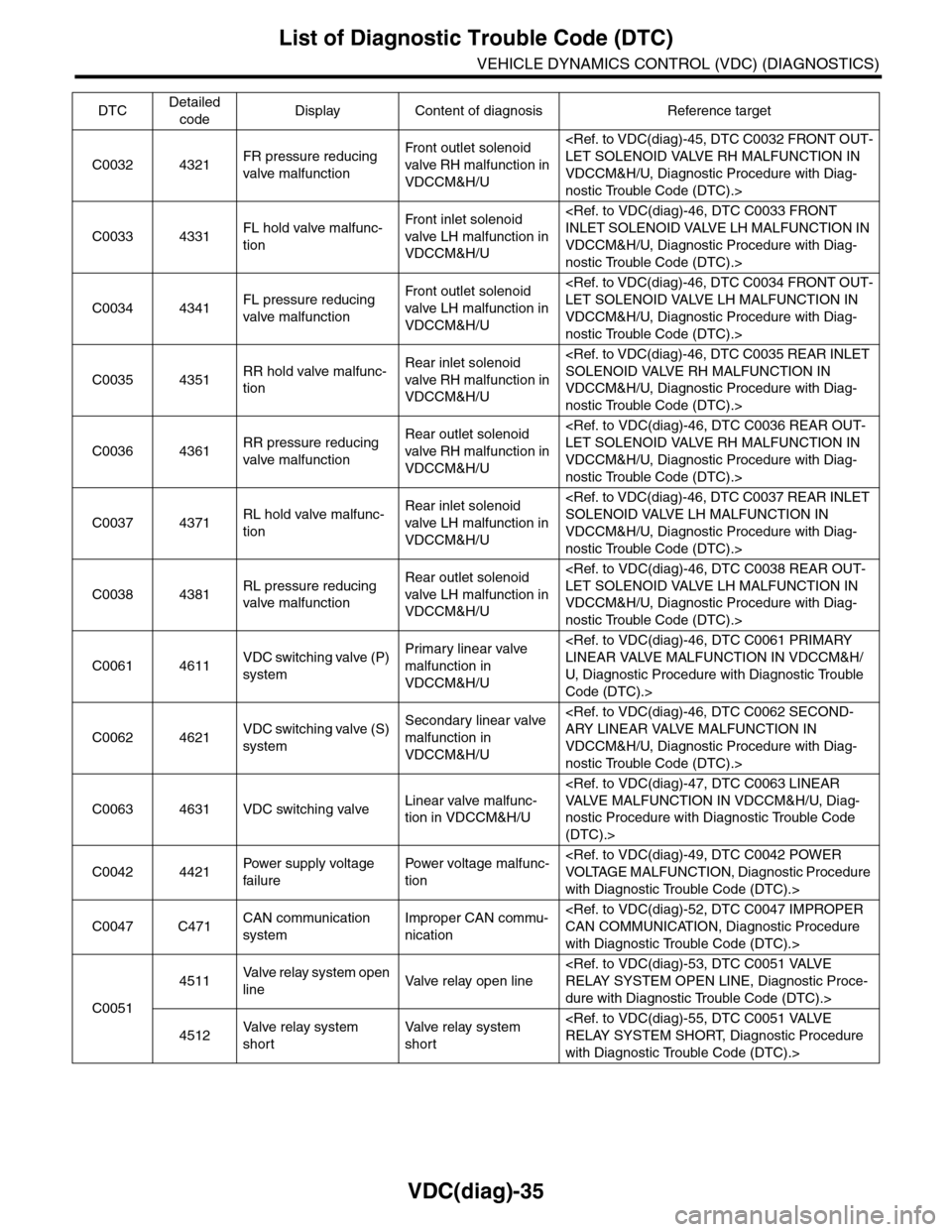
VDC(diag)-35
List of Diagnostic Trouble Code (DTC)
VEHICLE DYNAMICS CONTROL (VDC) (DIAGNOSTICS)
C0032 4321FR pressure reducing
valve malfunction
Fr o nt o ut l et s ol en o id
valve RH malfunction in
VDCCM&H/U
VDCCM&H/U, Diagnostic Procedure with Diag-
nostic Trouble Code (DTC).>
C0033 4331FL hold valve malfunc-
tion
Fr o nt i nl e t s ol e no i d
valve LH malfunction in
VDCCM&H/U
VDCCM&H/U, Diagnostic Procedure with Diag-
nostic Trouble Code (DTC).>
C0034 4341FL pressure reducing
valve malfunction
Fr o nt o ut l et s ol en o id
valve LH malfunction in
VDCCM&H/U
VDCCM&H/U, Diagnostic Procedure with Diag-
nostic Trouble Code (DTC).>
C0035 4351RR hold valve malfunc-
tion
Rear inlet solenoid
valve RH malfunction in
VDCCM&H/U
VDCCM&H/U, Diagnostic Procedure with Diag-
nostic Trouble Code (DTC).>
C0036 4361RR pressure reducing
valve malfunction
Rear outlet solenoid
valve RH malfunction in
VDCCM&H/U
VDCCM&H/U, Diagnostic Procedure with Diag-
nostic Trouble Code (DTC).>
C0037 4371RL hold valve malfunc-
tion
Rear inlet solenoid
valve LH malfunction in
VDCCM&H/U
VDCCM&H/U, Diagnostic Procedure with Diag-
nostic Trouble Code (DTC).>
C0038 4381RL pressure reducing
valve malfunction
Rear outlet solenoid
valve LH malfunction in
VDCCM&H/U
VDCCM&H/U, Diagnostic Procedure with Diag-
nostic Trouble Code (DTC).>
C0061 4611VDC switching valve (P)
system
Primary linear valve
malfunction in
VDCCM&H/U
U, D iagnostic Procedure with Diagnostic Trouble
Code (DTC).>
C0062 4621VDC switching valve (S)
system
Secondary linear valve
malfunction in
VDCCM&H/U
VDCCM&H/U, Diagnostic Procedure with Diag-
nostic Trouble Code (DTC).>
C0063 4631 VDC switching valveLinear valve malfunc-
tion in VDCCM&H/U
nostic Procedure with Diagnostic Trouble Code
(DTC).>
C0042 4421Pow er s up p ly vo lt a ge
failure
Powe r vo lt a ge ma lf u nc -
tion
with Diagnostic Trouble Code (DTC).>
C0047 C471CAN communication
system
Improper CAN commu-
nication
with Diagnostic Trouble Code (DTC).>
C0051
4511Va l ve r e l a y s y s t e m o p e n
lineVa l ve r e l ay o p e n l i n e
dure with Diagnostic Trouble Code (DTC).>
4512Va l ve r e l ay s y s t e m
short
Va l ve r e l ay s y s t e m
short
with Diagnostic Trouble Code (DTC).>
DTCDetailed
codeDisplay Content of diagnosis Reference target