2009 SUBARU TRIBECA wheel
[x] Cancel search: wheelPage 571 of 2453

OD(diag)-3
Check List for Interview
OCCUPANT DETECTION SYSTEM (DIAGNOSTICS)
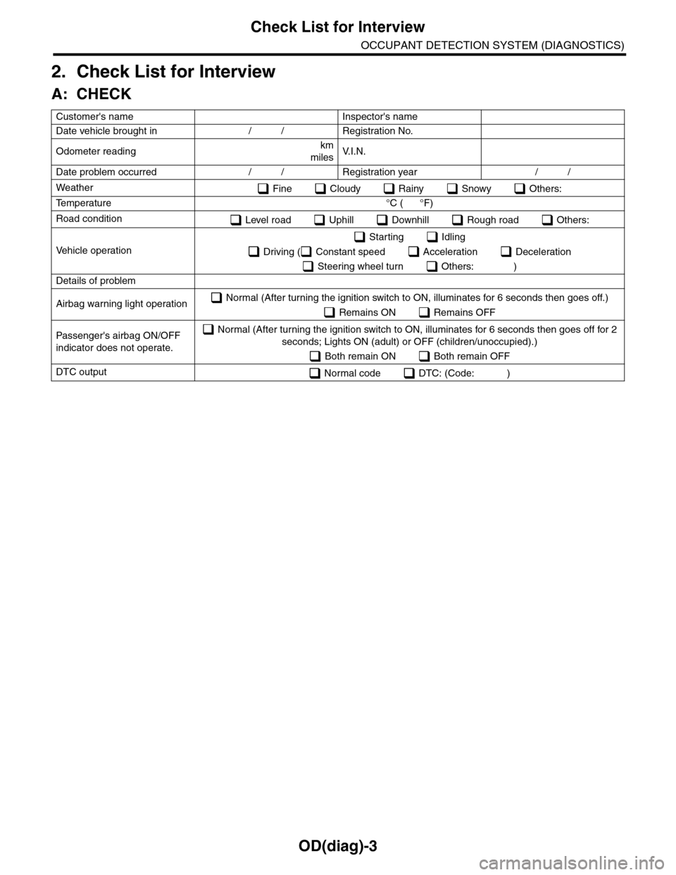
2. Check List for Interview
A: CHECK
Customer's name Inspector's name
Date vehicle brought in / / Registration No.
Odometer readingkm
milesV. I . N .
Date problem occurred / / Registration year / /
Weather Fine Cloudy Rainy Snowy Others:
Te m p e r a t u r e ° C ( ° F )
Road condition Level road Uphill Downhill Rough road Others:
Ve h i c l e o p e r a t i o n
Starting Idling
Driving ( Constant speed Acceleration Deceleration
Steering wheel turn Others: )
Details of problem
Airbag warning light operation Normal (After turning the ignition switch to ON, illuminates for 6 seconds then goes off.)
Remains ON Remains OFF
Passenger's airbag ON/OFF
indicator does not operate.
Normal (After turning the ignition switch to ON, illuminates for 6 seconds then goes off for 2
seconds; Lights ON (adult) or OFF (children/unoccupied).)
Both remain ON Both remain OFF
DTC output Normal code DTC: (Code: )
Page 606 of 2453

SB-9
Seat Belt Warning System
SEAT BELT SYSTEM
9CHECK BODY INTEGRATED MODULE.
Measure the voltage between connector (i84)
and chassis ground.
Connector & terminal
(i84) No. 4 (+) — Chassis ground (–):
Is the voltage more than 10 V? Go to step 10.Check the body
integrated unit.
10 CHECK COMBINATION METER.
Measure the voltage between connector
(R167) and chassis ground.
Connector & terminal
(R167) No. 20 (+) — Chassis ground (–):
Is the voltage more than 10 V?
Also, does the seat belt warn-
ing light come on?
Go to step 11.Replace the body
integrated unit.
11 CHECK COMBINATION METER.
Measure the voltage between connector (i10)
and chassis ground.
Connector & terminal
(i10) No. 9 (+) — Chassis ground (–):
Is the voltage more than 10 V?
Also, does the seat belt warn-
ing light come on?
Go to step 12.Check the combi-
nation meter.
12 CHECK SEAT BELT WARNING SYSTEM.
1) Disconnect the driver’s seat belt.
2) Turn the ignition switch to ON.
Does the seat belt warning
buzzer beep and warning light
blink for 6 seconds after turn-
ing the ignition switch to ON?
Go to step 13.Replace the body
integrated unit.
13 CHECK SEAT BELT WARNING SYSTEM.
Wait for 6 seconds from the step 12 condition
(seat belt warning buzzer beeps and warning
light blinks).
Does the seat belt warning
light repeat illuminating/blink-
ing every 15-seconds, and the
warning buzzer beep?
Go to step 14.Replace the body
integrated unit.
14 CHECK SEAT BELT WARNING SYSTEM.
Connect the driver’s seat belt buckle in the
step 13 condition (seat belt warning light
repeat illuminating/blinking every 15-seconds,
and warning buzzer beeps).
Does the seat belt warning
light go off and the buzzer
stop?
Go to step 15.Replace the body
integrated unit.
15 CHECK SEAT BELT WARNING SYSTEM.
Disconnect the driver’s seat belt.
Does the seat belt warning
light repeat illuminating/ blink-
ing every 15-seconds?
Go to step 16.Replace the body
integrated unit.
16 CHECK SEAT BELT WARNING SYSTEM.
1) Lift-up the vehicle.
NOTE:
Raise all wheels off floor.
2) Start the engine, and set the vehicle speed
to more than 15 km/h (9 MPH).
NOTE:
When there is a speed difference between front
and rear wheels, the ABS or VDC warning may
light, but this does not indicate a malfunction.
When diagnosis is complete, perform clear
memory for VDC.
Does the seat belt warning
light repeat illuminating/ blink-
ing every 15-seconds?
Go to step 17.Replace the body
integrated unit.
17 CHECK SEAT BELT WARNING SYSTEM.
Connect the driver’s seat belt in the step 16
condition.
Does the seat belt warning
light go off and the buzzer
stop?
Go to step 18.Replace the body
integrated unit.
18 Seat Belt Warning System
Disconnect the driver’s seat belt in the step 17
condition.
Does the seat belt warning
light repeat illuminating/ blink-
ing every 15-seconds?
Go to step 19.Replace the body
integrated unit.
19 CHECK SEAT BELT WARNING SYSTEM.
Connect the driver’s seat belt.
Does the seat belt warning
light go off and the buzzer
stop?
A temporary con-
tact failure.
Replace the body
integrated unit.
Step Check Yes No
Page 701 of 2453

WW-6
Combination Switch (Wiper)
WIPER AND WASHER SYSTEMS
3. Combination Switch (Wiper)
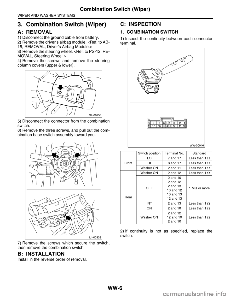
A: REMOVAL
1) Disconnect the ground cable from battery.
2) Remove the driver’s airbag module.
3) Remove the steering wheel.
4) Remove the screws and remove the steering
column covers (upper & lower).
5) Disconnect the connector from the combination
switch.
6) Remove the three screws, and pull out the com-
bination base switch assembly toward you.
7) Remove the screws which secure the switch,
then remove the combination switch.
B: INSTALLATION
Install in the reverse order of removal.
C: INSPECTION
1. COMBINATION SWITCH
1) Inspect the continuity between each connector
terminal.
2) If continuity is not as specified, replace the
switch.
SL-00258
LI -00332
Switch positionTerminal No.Standard
Fr o n t
LO 7 and 17 Less than 1 Ω
HI 8 and 17 Less than 1 Ω
Washer ON 2 and 11 Less than 1 Ω
Rear
Washer ON 2 and 12 Less than 1 Ω
OFF
2 and 10
2 and 12
2 and 13
10 and 12
10 and 13
12 and 13
1 MΩ or more
INT 2 and 13 Less than 1 Ω
ON 2 and 10 Less than 1 Ω
Washer ON
2 and 12
12 and 10
2 and 10
Less than 1 Ω
WW-00046
87654321917 16 15 14 13 12 11 1018
Page 726 of 2453

BR-12
Front Brake Pad
BRAKE
2. Front Brake Pad
A: REMOVAL
1) Lift-up the vehicle, and remove the front wheels.
2) Remove the caliper bolt.
3) Raise the caliper body and support it.
NOTE:
Do not disconnect the brake hose from the caliper
body.
4) Remove the pad.
B: INSTALLATION
1) Apply a thin coat of Molykote M7439 to the pad
clip.
2) Apply a thin coat of Molykote AS880N (Part No.
K0779YA010) to the contact surface between the
pad and pad inner shim.
3) Apply a thin coat of Molykote AS880N (Part No.
K0779YA010) to the three contact surfaces be-
tween inner shim and outer shim of outer pads.
BR-00339
BR-00012
BR-00340
BR-00238
BR-00341
Page 728 of 2453

BR-14
Front Disc Rotor
BRAKE
3. Front Disc Rotor
A: REMOVAL
1) Lift-up the vehicle, and remove the front wheels.
2) Remove the caliper body and the support from
housing, and suspend it from the strut using a wire.
3) Remove the disc rotor.
NOTE:
If it is difficult to remove the disc rotor from the hub,
drive an 8 mm bolt into the threaded section (B) of
the rotor, then remove the rotor.
4) Remove mud and foreign matter from the caliper
body assembly and support.
B: INSTALLATION
1) Install the disc rotor.
2) Install the caliper body and the support to hous-
ing.
Tightening torque:
120 N·m (12.2 kgf-m, 88.5 ft-lb)
3) Install the front wheels.
C: INSPECTION
1) Check the front wheel bearing play and axle hub
runout before the inspection of disc rotor runout
limit.
2) Secure the disc rotor by tightening the five wheel
nuts.
3) Set a dial gauge 10 mm (0. 39 in) inward from
the disc rotor outer circumference. Rotate the disc
rotor to check runout. If the disc rotor runout ex-
ceeds the limit, replace with a new disc rotor. After
grinding, check disk rotor thickness according to
step 4).
Disc rotor runout limit:
0.05 mm (0.0020 in)
4) Set a micrometer 10 mm (0.39 in) inward from
the disc rotor outer perimeter, and then measure
the disc rotor thickness. If the thickness of the disc
rotor exceeds the service limit, replace with a new
disc rotor.
BR-00017
B
A
BR-00018
Specification LimitDisc rotor
outer diameter
Disc rotor thick-
ness A
mm (in)
30 (1.18) 28 (1.10) 316 (12.44)
BR-00019
B
A
BR-00018
Page 729 of 2453

BR-15
Front Disc Brake Assembly
BRAKE
4. Front Disc Brake Assembly
A: REMOVAL
CAUTION:
Do not allow brake fluid to come in contact with
vehicle body. If it does, wash off with water and
wipe away completely.
1) Lift-up the vehicle, and remove the front wheels.
2) Remove the union bolt, and disconnect the
brake hose from the caliper body assembly.
3) Remove the bolt securing the lock pin to caliper
body.
4) Raise the caliper body, and then move it toward
vehicle center to separate it from the support.
5) Remove the support from housing.
NOTE:
Remove the support only when replacing the rotor
or support. It need not be removed when servicing
the caliper body assembly.
6) Remove mud and foreign matter from the caliper
body assembly and support.
B: INSTALLATION
1) Install the support to the housing.
Tightening torque:
120 N·m (12.2 kgf-m, 88.5 ft-lb)
2) Apply a thin coat of Molykote M7439 to the pad
clip.
3) Apply a thin coat of Molykote AS880N (Part No.
K0777YA010) to the contact surface between pad
and inner shim.
4) Apply a thin coat of Molykote AS880N (Part No.
K0779YA010) to the three contact surfaces be-
tween inner shim and outer shim of outer pads.
BR-00021
BR-00022
BR-00023
BR-00340
BR-00238
BR-00341
Page 733 of 2453

BR-19
Rear Brake Pad
BRAKE
5. Rear Brake Pad
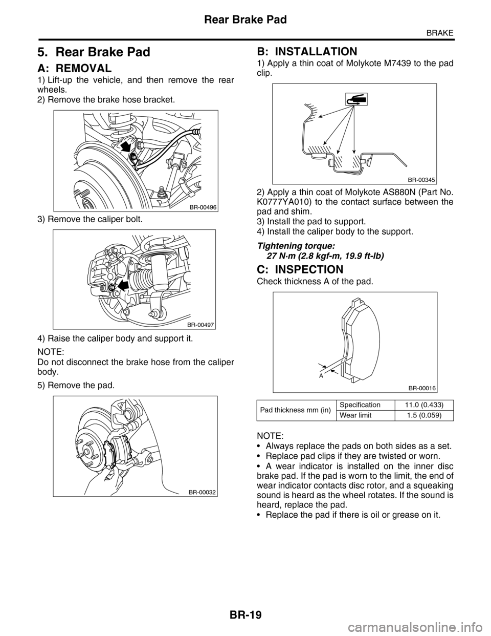
A: REMOVAL
1) Lift-up the vehicle, and then remove the rear
wheels.
2) Remove the brake hose bracket.
3) Remove the caliper bolt.
4) Raise the caliper body and support it.
NOTE:
Do not disconnect the brake hose from the caliper
body.
5) Remove the pad.
B: INSTALLATION
1) Apply a thin coat of Molykote M7439 to the pad
clip.
2) Apply a thin coat of Molykote AS880N (Part No.
K0777YA010) to the contact surface between the
pad and shim.
3) Install the pad to support.
4) Install the caliper body to the support.
Tightening torque:
27 N·m (2.8 kgf-m, 19.9 ft-lb)
C: INSPECTION
Check thickness A of the pad.
NOTE:
•Always replace the pads on both sides as a set.
•Replace pad clips if they are twisted or worn.
•A wear indicator is installed on the inner disc
brake pad. If the pad is worn to the limit, the end of
wear indicator contacts disc rotor, and a squeaking
sound is heard as the wheel rotates. If the sound is
heard, replace the pad.
•Replace the pad if there is oil or grease on it.
BR-00497
BR-00032
Pad thickness mm (in)Specification 11.0 (0.433)
Wear limit 1.5 (0.059)
BR-00345
A
BR-00016
Page 734 of 2453

BR-20
Rear Disc Rotor
BRAKE
6. Rear Disc Rotor
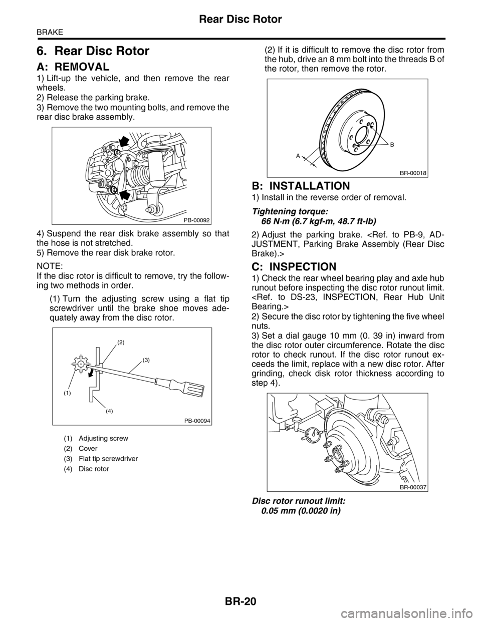
A: REMOVAL
1) Lift-up the vehicle, and then remove the rear
wheels.
2) Release the parking brake.
3) Remove the two mounting bolts, and remove the
rear disc brake assembly.
4) Suspend the rear disk brake assembly so that
the hose is not stretched.
5) Remove the rear disk brake rotor.
NOTE:
If the disc rotor is difficult to remove, try the follow-
ing two methods in order.
(1) Turn the adjusting screw using a flat tip
screwdriver until the brake shoe moves ade-
quately away from the disc rotor.
(2) If it is difficult to remove the disc rotor from
the hub, drive an 8 mm bolt into the threads B of
the rotor, then remove the rotor.
B: INSTALLATION
1) Install in the reverse order of removal.
Tightening torque:
66 N·m (6.7 kgf-m, 48.7 ft-lb)
2) Adjust the parking brake.
Brake).>
C: INSPECTION
1) Check the rear wheel bearing play and axle hub
runout before inspecting the disc rotor runout limit.
2) Secure the disc rotor by tightening the five wheel
nuts.
3) Set a dial gauge 10 mm (0. 39 in) inward from
the disc rotor outer circumference. Rotate the disc
rotor to check runout. If the disc rotor runout ex-
ceeds the limit, replace with a new disc rotor. After
grinding, check disk rotor thickness according to
step 4).
Disc rotor runout limit:
0.05 mm (0.0020 in)
(1) Adjusting screw
(2) Cover
(3) Flat tip screwdriver
(4) Disc rotor
PB-00092
(1)
(4)
(2)
(3)
PB-00094
B
A
BR-00018
BR-00037