2009 SUBARU TRIBECA warning
[x] Cancel search: warningPage 1984 of 2453
SC(H6DO)-26
Battery
STARTING/CHARGING SYSTEMS
3. SPECIFIC GRAVITY OF ELECTROLYTE
1) Measure specific gravity of electrolyte using a
hydrometer and a thermometer.
Specific gravity varies with temperature of electro-
lyte so that it must be corrected at 20°C (68°F) us-
ing the following equation:
S20 = St + 0.0007 × (t – 20)
S20: Specific gravity corrected at electrolyte
temperature of 20°C (68°F)
St: Measured specific gravity
t: Measured temperature (°C)
Determine whether or not battery must be
charged, according to corrected specific
gravity.
Standard specific gravity: 1.220 — 1.290
[20°C (68°F)]
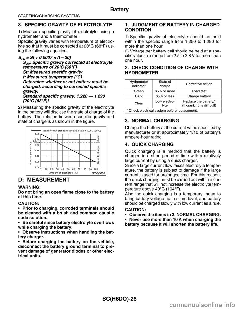
2) Measuring the specific gravity of the electrolyte
in the battery will disclose the state of charge of the
battery. The relation between specific gravity and
state of charge is as shown in the figure.
D: MEASUREMENT
WARNING:
Do not bring an open flame close to the battery
at this time.
CAUTION:
•Prior to charging, corroded terminals should
be cleaned with a brush and common caustic
soda solution.
•Be careful since battery electrolyte overflows
while charging the battery.
•Observe instructions when handling the bat-
tery charger.
•Before charging the battery on the vehicle,
disconnect the battery ground terminal to pre-
vent damage of generator diodes or other elec-
trical units.
1. JUDGMENT OF BATTERY IN CHARGED
CONDITION
1) Specific gravity of electrolyte should be held
within the specific range from 1.250 to 1.290 for
more than one hour.
2) Voltage per battery cell should be held at a spe-
cific value in a range from 2.5 to 2.8 V for more than
one hour.
2. CHECK CONDITION OF CHARGE WITH
HYDROMETER
3. NORMAL CHARGING
Charge the battery at the current value specified by
manufacturer or at approximately 1/10 of battery's
ampere-hour rating.
4. QUICK CHARGING
Quick charging is a method that the battery is
charged in a short period of time with a relatively
large current by using a quick charger.
Since a large current flow raises electrolyte temper-
ature, the battery is subject to damage if the large
current is used for prolonged time. For this reason,
the quick charging must be carried out within a cur-
rent range that will not increase the electrolyte tem-
perature above 40°C (104°F).
Also the quick charging is a temporary mean to
bring battery voltage up to some level, and battery
should be charged slowly with low current as a rule.
CAUTION:
•Observe the items in 3. NORMAL CHARGING.
•Never use more than 10 A when charging the
battery because it will shorten the battery life.
SC-00054
010 20 30 40 50 60 70 80 90 100
1.12
1.20
1.16
1.24
1.28
1.22
1.08
1.04
Amount of discharge (%)
Specific gravity ( C)
Battery with standard specific gravity 1,280 (20 C)
Good
Need to charge
Hydrometer
indicator
State of
chargeCorrective action
Green 65% or more Load test
Dark 65% or less Charge battery
ClearLow electro-
lyte
Replace the battery.*
(If cranking is difficult)
* Check electrical system before replacement.
Page 1997 of 2453
PM-14
Engine Coolant
PERIODIC MAINTENANCE SERVICES
10.Engine Coolant
A: REPLACEMENT
1. REPLACEMENT OF ENGINE COOLANT
WARNING:
The radiator is of the pressurized type. Do not
attempt to open the radiator cap immediately
after the engine has been stopped.
1) Lift-up the vehicle.
2) Remove the under cover.
3) Place a container under drain pipe.
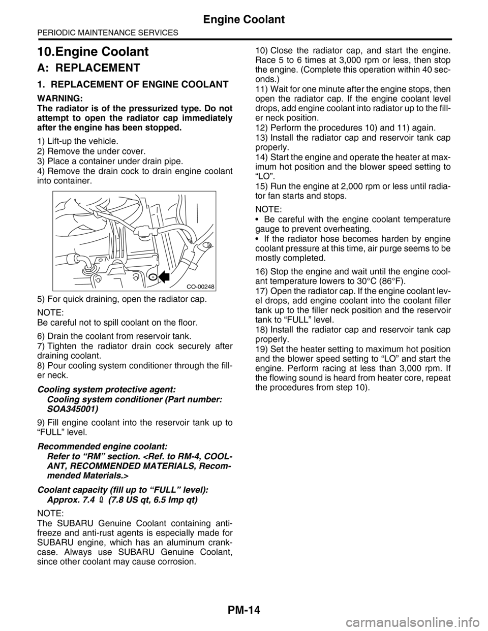
4) Remove the drain cock to drain engine coolant
into container.
5) For quick draining, open the radiator cap.
NOTE:
Be careful not to spill coolant on the floor.
6) Drain the coolant from reservoir tank.
7) Tighten the radiator drain cock securely after
draining coolant.
8) Pour cooling system conditioner through the fill-
er neck.
Cooling system protective agent:
Cooling system conditioner (Part number:
SOA345001)
9) Fill engine coolant into the reservoir tank up to
“FULL” level.
Recommended engine coolant:
Refer to “RM” section.
mended Materials.>
Coolant capacity (fill up to “FULL” level):
Approx. 7.4 2 (7.8 US qt, 6.5 Imp qt)
NOTE:
The SUBARU Genuine Coolant containing anti-
freeze and anti-rust agents is especially made for
SUBARU engine, which has an aluminum crank-
case. Always use SUBARU Genuine Coolant,
since other coolant may cause corrosion.
10) Close the radiator cap, and start the engine.
Race 5 to 6 times at 3,000 rpm or less, then stop
the engine. (Complete this operation within 40 sec-
onds.)
11) Wait for one minute after the engine stops, then
open the radiator cap. If the engine coolant level
drops, add engine coolant into radiator up to the fill-
er neck position.
12) Perform the procedures 10) and 11) again.
13) Install the radiator cap and reservoir tank cap
properly.
14) Start the engine and operate the heater at max-
imum hot position and the blower speed setting to
“LO”.
15) Run the engine at 2,000 rpm or less until radia-
tor fan starts and stops.
NOTE:
•Be careful with the engine coolant temperature
gauge to prevent overheating.
•If the radiator hose becomes harden by engine
coolant pressure at this time, air purge seems to be
mostly completed.
16) Stop the engine and wait until the engine cool-
ant temperature lowers to 30°C (86°F).
17) Open the radiator cap. If the engine coolant lev-
el drops, add engine coolant into the coolant filler
tank up to the filler neck position and the reservoir
tank to “FULL” level.
18) Install the radiator cap and reservoir tank cap
properly.
19) Set the heater setting to maximum hot position
and the blower speed setting to “LO” and start the
engine. Perform racing at less than 3,000 rpm. If
the flowing sound is heard from heater core, repeat
the procedures from step 10).
CO-00248
Page 2002 of 2453
PM-19
Brake Line
PERIODIC MAINTENANCE SERVICES
13.Brake Line
A: INSPECTION
1. BRAKE LINE
1) Check for scratches, swelling, corrosion, traces
of fluid leakage on the brake hoses or pipe joints.
2) Check the possibility of adjacent parts interfering
with brake pipes/hoses during driving, and loose
connections/clamps.
3) Check any trace of fluid leakage, scratches, etc.
on master cylinder, wheel cylinder and pressure
control valve.
NOTE:
•When the brake fluid level in the reservoir tank is
lower than specified limit, the brake warning light
on the combination meter will come on.
•Visually check the brake hose for damage. (Use
a mirror where it is difficult to see)
2. SERVICE BRAKE
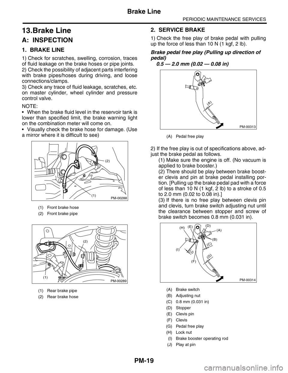
1) Check the free play of brake pedal with pulling
up the force of less than 10 N (1 kgf, 2 lb).
Brake pedal free play (Pulling up direction of
pedal)
0.5 — 2.0 mm (0.02 — 0.08 in)
2) If the free play is out of specifications above, ad-
just the brake pedal as follows.
(1) Make sure the engine is off. (No vacuum is
applied to brake booster.)
(2) There should be play between brake boost-
er clevis and pin at brake pedal installing por-
tion. [Pulling up the brake pedal pad with a force
of less than 10 N (1 kgf, 2 lb) to a stroke of 0.5
to 2.0 mm (0.02 to 0.08 in).]
(3) If there is no free play between clevis pin
and clevis, turn brake switch adjusting nut until
the clearance between stopper and screw of
brake switch becomes 0.8 mm (0.031 in).
(1) Front brake hose
(2) Front brake pipe
(1) Rear brake pipe
(2) Rear brake hose
PM-00288
(2)
(1)
PM-00289(1)
(2)
(A) Pedal free play
(A) Brake switch
(B) Adjusting nut
(C) 0.8 mm (0.031 in)
(D) Stopper
(E) Clevis pin
(F) Clevis
(G) Pedal free play
(H) Lock nut
(I) Brake booster operating rod
(J) Play at pin
PM-00313
(A)
PM-00314
(G)
(A)(D)(E)
(B)
(C)
(F)
(J)(I)
(H)
Page 2015 of 2453
PM-32
Supplemental Restraint System
PERIODIC MAINTENANCE SERVICES
22.Supplemental Restraint System
A: INSPECTION
Check the airbag system in accordance with the result of the self-diagnosis.
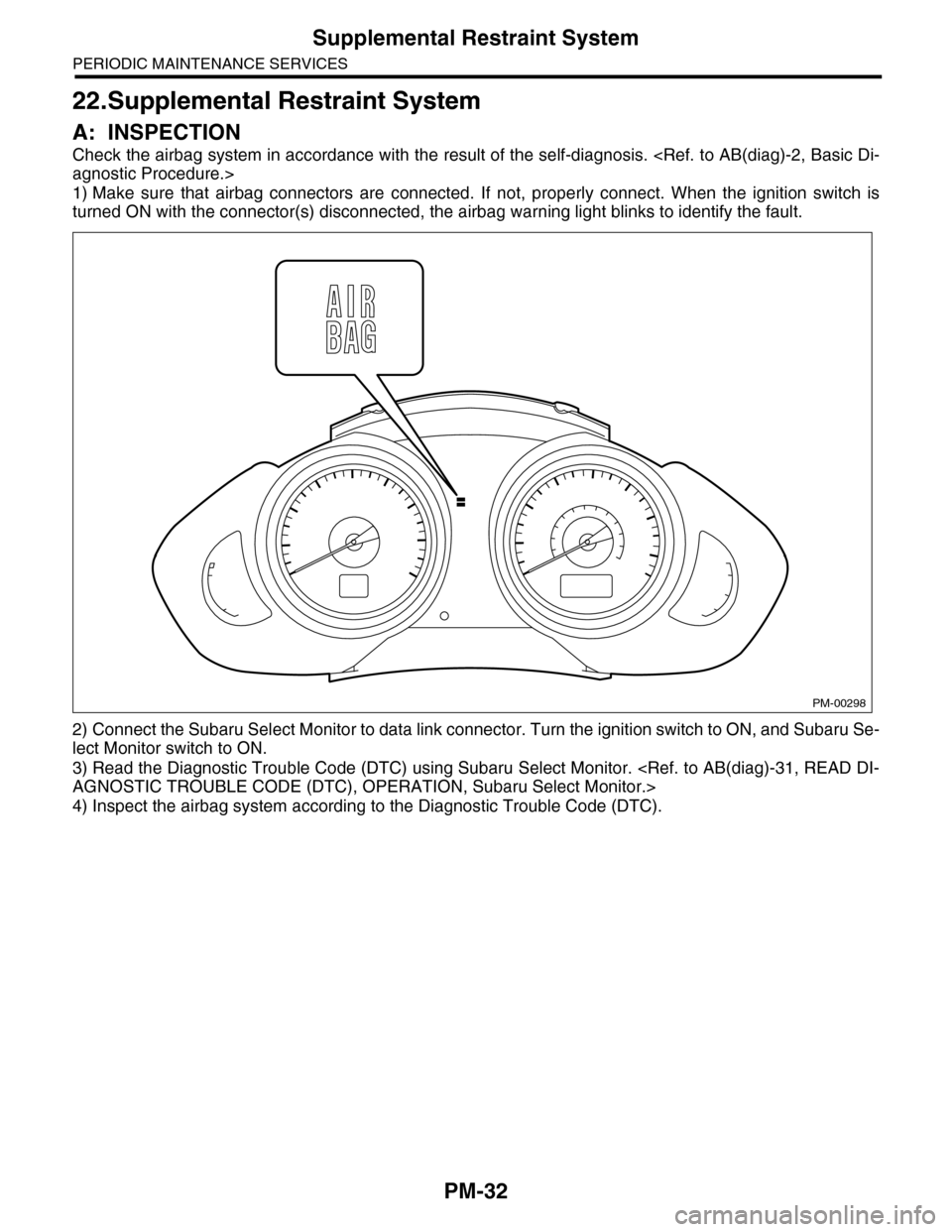
1) Make sure that airbag connectors are connected. If not, properly connect. When the ignition switch is
turned ON with the connector(s) disconnected, the airbag warning light blinks to identify the fault.
2) Connect the Subaru Select Monitor to data link connector. Turn the ignition switch to ON, and Subaru Se-
lect Monitor switch to ON.
3) Read the Diagnostic Trouble Code (DTC) using Subaru Select Monitor.
4) Inspect the airbag system according to the Diagnostic Trouble Code (DTC).
PM-00298
Page 2123 of 2453
5AT(diag)-6
General Description
AUTOMATIC TRANSMISSION (DIAGNOSTICS)
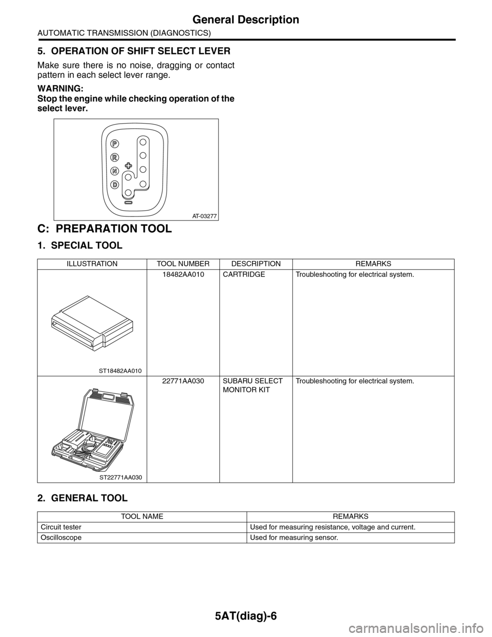
5. OPERATION OF SHIFT SELECT LEVER
Make sure there is no noise, dragging or contact
pattern in each select lever range.
WARNING:
Stop the engine while checking operation of the
select lever.
C: PREPARATION TOOL
1. SPECIAL TOOL
2. GENERAL TOOL
AT-03277
ILLUSTRATION TOOL NUMBER DESCRIPTION REMARKS
18482AA010 CARTRIDGE Troubleshooting for electrical system.
22771AA030 SUBARU SELECT
MONITOR KIT
Tr o u b l e s h o o t i n g f o r e l e c t r i c a l s y s t e m .
TOOL NAME REMARKS
Circuit tester Used for measuring resistance, voltage and current.
Oscilloscope Used for measuring sensor.
ST18482AA010
ST22771AA030
Page 2124 of 2453
5AT(diag)-7
Electrical Component Location
AUTOMATIC TRANSMISSION (DIAGNOSTICS)
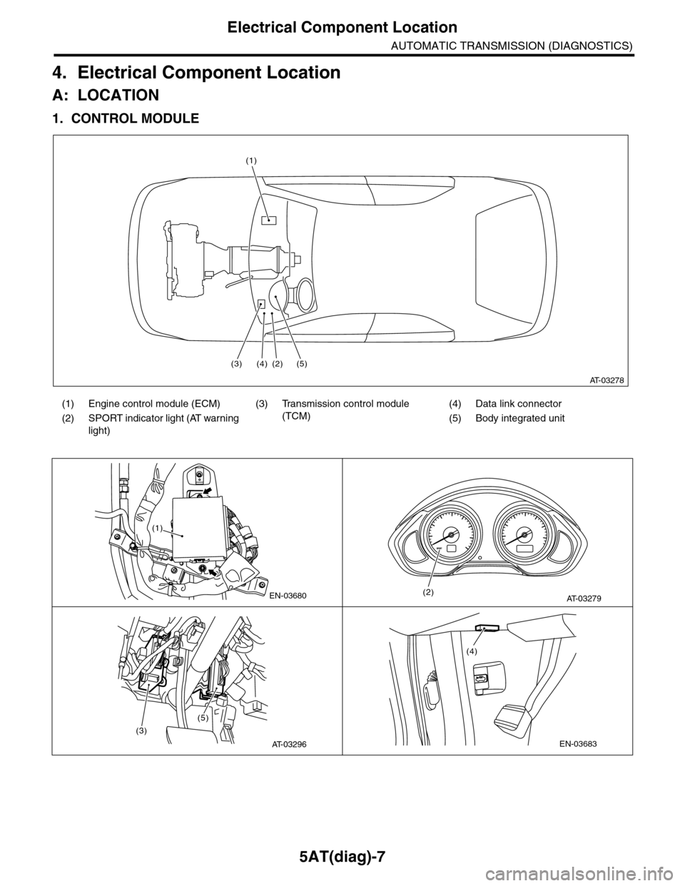
4. Electrical Component Location
A: LOCATION
1. CONTROL MODULE
(1) Engine control module (ECM) (3) Transmission control module
(TCM)
(4) Data link connector
(2) SPORT indicator light (AT warning
light)
(5) Body integrated unit
AT-03278
(1)
(3)(4) (2) (5)
EN-03680
(1)
AT-03279(2)
(3)
(5)
AT-03296EN-03683
(4)
Page 2136 of 2453
5AT(diag)-19
Inspection Mode
AUTOMATIC TRANSMISSION (DIAGNOSTICS)
8. Inspection Mode
A: PROCEDURE
WARNING:
Observe the traffic law during driving on roads.
1) Shift the select lever to “D” range, and then drive
the vehicle with changing the gear from 1st to 5th.
2) When driving the vehicle at 5th speed of “D”
range, set the gear to manual mode and drive the
vehicle by downshifting using “–” of the select lever
from 5th → 4th, 4th → 3rd, 3rd → 2nd, and 2nd →
1st.
NOTE:
At shifting down, drive the vehicle at least 10 sec-
onds in each speed.
3) Shift the select lever to “R” range and drive the
vehicle for more than 2 seconds.
Page 2160 of 2453
5AT(diag)-43
Diagnostic Procedure with Diagnostic Trouble Code (DTC)
AUTOMATIC TRANSMISSION (DIAGNOSTICS)
7CHECK HARNESS ASSEMBLY.
1) Turn the ignition switch to OFF.
2) Disconnect the connector from transmis-
sion.
3) Disconnect the connector from turbine
speed sensor 1.
4) Measure the resistance between transmis-
sion connector and turbine speed sensor 1
connector.
Connector & terminal
(T4) No. 7 — (AT1) No. 3:
(T3) No. 7 — (AT1) No. 2:
(AT1) No. 1 — Chassis ground:
Is the resistance less than 1
Ω?
Go to step 8.Repair the open
circuit of harness
between TCM and
transmission con-
nector, or poor
contact of connec-
tor.
8CHECK HARNESS ASSEMBLY.
Measure the resistance between transmission
connector and chassis ground.
Connector & terminal
(T4) No. 7 — Chassis ground:
(T3) No. 7 — Chassis ground:
Is the resistance more than 1
MΩ?
Go to step 9.Repair the short
circuit of harness
between TCM and
transmission con-
nector.
9CHECK INPUT SIGNAL FOR TCM USING
SUBARU SELECT MONITOR.
1) Connect all the connectors.
2) Lift-up the vehicle and support with rigid
racks.
NOTE:Raise all wheels off floor.
3) Start the engine, and set the vehicle in 4th
speed driving condition of manual mode.
NOTE:Turbine speed sensor 1 signal can be mea-
sured only on 4th speed.
4) Read the current data of turbine speed sen-
sor 1 using the Subaru Select Monitor.
AT I O N , S u b a r u S e l e c t M o n i t o r . >
NOTE:The speed difference between front and rear
wheels may light the ABS warning light, but this
indicates no malfunction. When AT control di-
agnosis is finished, perform the VDC memory
clearance procedure of on-board diagnostics
system.
Does the value of the turbine
speed sensor 1 change
depending on the acceleration,
deceleration and shifting range
of the vehicle?
Even if the SPORT
indicator light
blinks, the system
is in normal condi-
tion. A temporary
poor contact of
connector or har-
ness may be the
cause. Repair the
poor contact of
harness between
AT F t e m p e r a t u r e
sensor and trans-
mission connector.
Replace the tur-
bine speed sensor
1.
Sensor 1.>
Step Check Yes No