2009 SUBARU TRIBECA warning
[x] Cancel search: warningPage 1092 of 2453
VDC-11
VDC Control Module & Hydraulic Control Unit (VDCCM&H/U)
VEHICLE DYNAMICS CONTROL (VDC)
D: ADJUSTMENT
When the following replacement, removal and in-
stallation are performed, be sure to perform center-
ing of the steering angle sensor and zero point
setting of the yaw rate & G sensor.
•VDCCM&H/U
•Steering angle sensor
•Yaw rate & lateral G sensor
•Steering wheel parts (Including airbag)
•Suspension parts
•Wheel alignment adjustment
1) Park the vehicle straight on a level surface. (En-
gine operation in the “P” or “N” range)
2) Check that steering wheel is positioned at the
center. (When the center position is not correct, ad-
just the wheel alignment.)
3) Set the Subaru Select Monitor to the vehicle,
and select {Set up mode for Neutral of Steering An-
gle Sensor & Lateral G Sensor 0 point} in the
“Function check sequence” screen. (Follow the
procedures shown in the display.)
4) On the “Brake Control System” display screen,
select {Current Data Display & Save}, and check
that the steering angle sensor shows “0 deg”.
5) When the “0 deg” is not displayed, repeat the
above steps and check that the “0 deg” is dis-
played.
6) Drive the vehicle for 10 minutes, and check that
the ABS and VDC warning light is not illuminated.
7) Check that there is no unnecessary VDC opera-
tion or steering control loss. If there is a problem,
repeat the steps above.
Page 1095 of 2453
VDC-14
ABS Sequence Control
VEHICLE DYNAMICS CONTROL (VDC)
NOTE:
The control operation starts from point A.
B: SPECIFICATION
1. ABS SEQUENCE CONTROL COMPLETE
CONDITION
When the following conditions develop, the ABS
sequence control stops and ABS operation is re-
turned to the normal control mode.
1) When the speed of at least one wheel reaches
10 km/h (6 MPH).
2) When the brake pedal is released during ABS
sequence control and the stop lamp switch is be-
comes OFF.
3) After completion of ABS sequence control.
4) When a malfunction is detected.
(1) All wheel speed (10) RR decompression valve (18) 1.0 seconds
(2) Ignition key (11) RR hold valve (19) 1.4 seconds
(3) ABS warning light (12) RL decompression valve (20) 0.6 seconds
(4) Stop light switch (13) RL hold valve (21) 0.4 seconds
(5) Valve relay (14) Pump motor (22) Point A
(6) FL decompression valve (15) 1.5 seconds (23) Reset
(7) FL hold valve (16) Light OFF (24) Linear valve 1
(8) FR decompression valve (17) Light ON (25) Linear valve 2
(9) FR hold valve
Page 1098 of 2453
VDC-17
VDC Sequence Control
VEHICLE DYNAMICS CONTROL (VDC)
NOTE:
The control operation starts from point A.
B: SPECIFICATION
1. CONDITIONS FOR COMPLETION OF
VDC SEQUENCE CONTROL
When the following conditions develop, the VDC
sequence control stops and VDC operation is re-
turned to the normal control mode.
1) When the speed of at least one wheel reaches
10 km/h (6 MPH).
2) When the brake pedal is pressed during se-
quence control and the stop light switch is set to
ON.
3) After completion of VDC sequence control.
4) When a malfunction is detected.
(1) All wheel speed (11) FR compression valve (21) Light OFF
(2) Ignition key (12) RR decompression valve (22) Light ON
(3) ABS warning light (13) RR compression valve (23) 3.4 seconds
(4) VDC warning light (14) RL decompression valve (24) 1 second
(5) VDC operation lamp (CAN output) (15) RL compression valve (25) 1.6 seconds
(6) Stop light switch (16) Pump motor (26) Point A
(7) Valve relay (17) Linear valve 1 (27) Reset
(8) FL decompression valve (18) Linear valve 2 (28) 0.8 seconds
(9) FL compression valve (19) 1.5 seconds (29) 1.2 seconds
(10) FR decompression valve (20) Approx. 3 sec. (30) 0.4 seconds
Page 1100 of 2453
VDC-19
Steering Angle Sensor
VEHICLE DYNAMICS CONTROL (VDC)
6. Steering Angle Sensor
A: REPLACEMENT
CAUTION:
•Do not perform the removal except when the
replacement.
•When replacing more than three times, re-
place the combination switch as assembly to
protect the threads.
1) Set the steering wheel in a straight-ahead posi-
tion.
2) Disconnect the ground cable from the battery.
3) Remove the airbag module.
WARNING:
Always refer to “Airbag System” when perform-
ing the airbag module repair service.
4) Remove the steering wheel.
5) Remove the screws and remove the steering
column lower cover.
6) Remove the two screws securing the steering
column upper cover.
7) Unlock the harness band and disconnect the
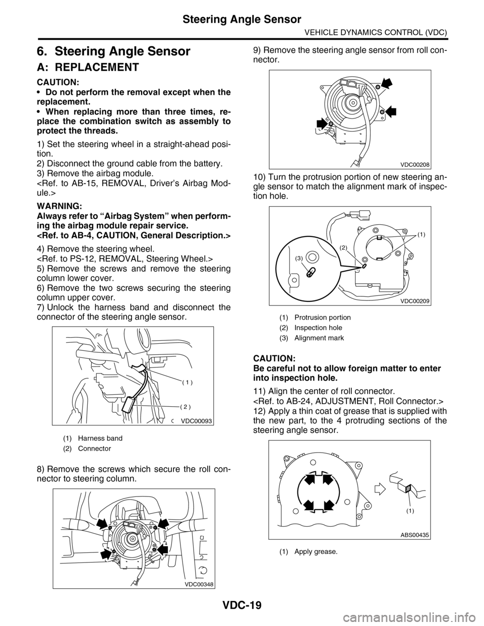
connector of the steering angle sensor.
8) Remove the screws which secure the roll con-
nector to steering column.
9) Remove the steering angle sensor from roll con-
nector.
10) Turn the protrusion portion of new steering an-
gle sensor to match the alignment mark of inspec-
tion hole.
CAUTION:
Be careful not to allow foreign matter to enter
into inspection hole.
11) Align the center of roll connector.
12) Apply a thin coat of grease that is supplied with
the new part, to the 4 protruding sections of the
steering angle sensor.
(1) Harness band
(2) Connector
VDC00093
( 1 )
( 2 )
VDC00348
(1) Protrusion portion
(2) Inspection hole
(3) Alignment mark
(1) Apply grease.
VDC00208
VDC00209
(1)
(2)
(3)
ABS00435
(1)
Page 1101 of 2453
VDC-20
Steering Angle Sensor
VEHICLE DYNAMICS CONTROL (VDC)
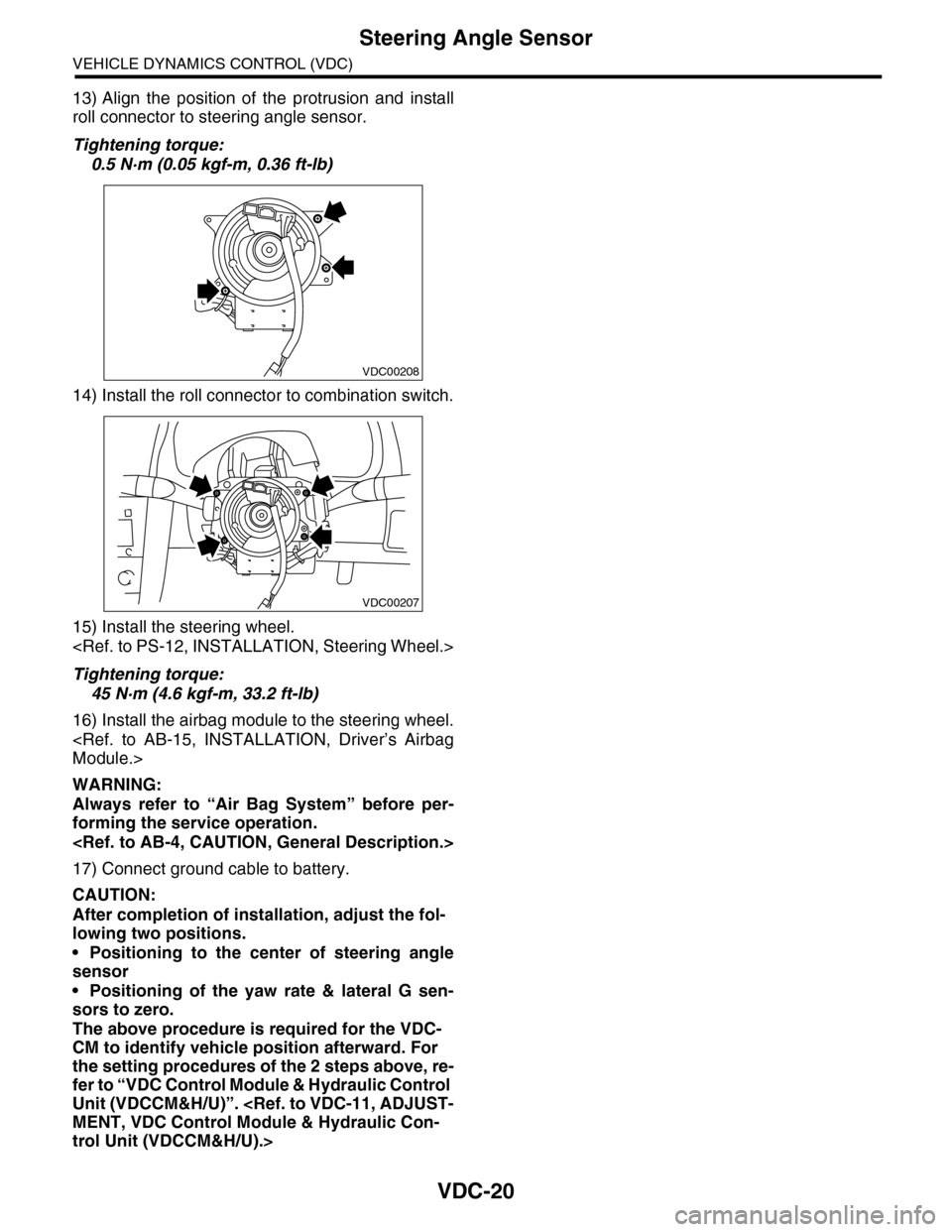
13) Align the position of the protrusion and install
roll connector to steering angle sensor.
Tightening torque:
0.5 N·m (0.05 kgf-m, 0.36 ft-lb)
14) Install the roll connector to combination switch.
15) Install the steering wheel.
Tightening torque:
45 N·m (4.6 kgf-m, 33.2 ft-lb)
16) Install the airbag module to the steering wheel.
WARNING:
Always refer to “Air Bag System” before per-
forming the service operation.
17) Connect ground cable to battery.
CAUTION:
After completion of installation, adjust the fol-
lowing two positions.
•Positioning to the center of steering angle
sensor
•Positioning of the yaw rate & lateral G sen-
sors to zero.
The above procedure is required for the VDC-
CM to identify vehicle position afterward. For
the setting procedures of the 2 steps above, re-
fer to “VDC Control Module & Hydraulic Control
Unit (VDCCM&H/U)”.
trol Unit (VDCCM&H/U).>
VDC00208
VDC00207
Page 1134 of 2453
CO(H6DO)-15
Radiator
COOLING
6. Radiator
A: REMOVAL
WARNING:
The radiator is pressurized. Wait until engine
cools down before working on the radiator.
1) Set the vehicle on a lift.
2) Remove the collector cover.
3) Disconnect the ground cable from battery.
4) Lift-up the vehicle.
5) Remove the under cover.
6) Drain engine coolant completely.
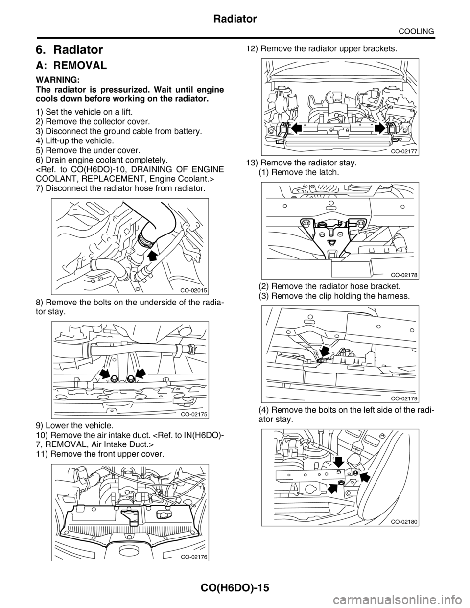
7) Disconnect the radiator hose from radiator.
8) Remove the bolts on the underside of the radia-
tor stay.
9) Lower the vehicle.
10) Remove the air intake duct.
11) Remove the front upper cover.
12) Remove the radiator upper brackets.
13) Remove the radiator stay.
(1) Remove the latch.
(2) Remove the radiator hose bracket.
(3) Remove the clip holding the harness.
(4) Remove the bolts on the left side of the radi-
ator stay.
CO-02015
CO-02175
CO-02176
CO-02177
CO-02179
CO-02180
Page 1165 of 2453
EN(H6DO)(diag)-4
Check List for Interview
ENGINE (DIAGNOSTICS)
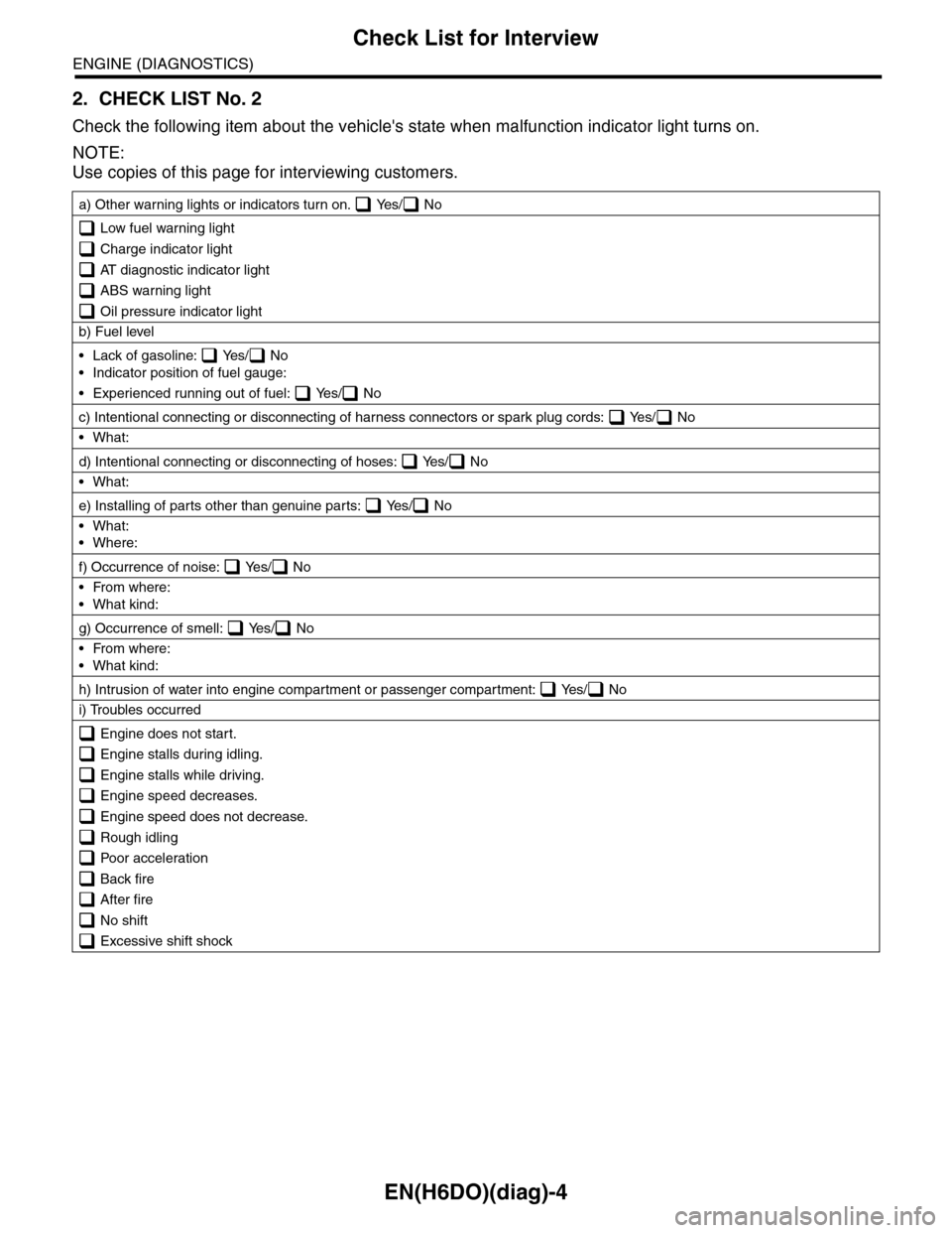
2. CHECK LIST No. 2
Check the following item about the vehicle's state when malfunction indicator light turns on.
NOTE:
Use copies of this page for interviewing customers.
a) Other warning lights or indicators turn on. Yes/ No
Low fuel warning light
Charge indicator light
AT diagnostic indicator light
ABS warning light
Oil pressure indicator light
b) Fuel level
•Lack of gasoline: Yes/ No
•Indicator position of fuel gauge:
•Experienced running out of fuel: Yes/ No
c) Intentional connecting or disconnecting of harness connectors or spark plug cords: Yes/ No
•What:
d) Intentional connecting or disconnecting of hoses: Yes/ No
•What:
e) Installing of parts other than genuine parts: Yes/ No
•What:
•Where:
f) Occurrence of noise: Yes/ No
•From where:
•What kind:
g) Occurrence of smell: Yes/ No
•From where:
•What kind:
h) Intrusion of water into engine compartment or passenger compartment: Yes/ No
i) Troubles occurred
Engine does not start.
Engine stalls during idling.
Engine stalls while driving.
Engine speed decreases.
Engine speed does not decrease.
Rough idling
Poor acceleration
Back fire
After fire
No shift
Excessive shift shock
Page 1166 of 2453
EN(H6DO)(diag)-5
General Description
ENGINE (DIAGNOSTICS)
3. General Description
A: CAUTION
1) Airbag system wiring harness is routed near the
ECM, main relay and fuel pump relay.
CAUTION:
•All airbag system wiring harnesses and con-
nectors are colored yellow. Do not use electri-
cal test equipment on these circuits.
•Be careful not to damage the airbag system
wiring harness when servicing the ECM, TCM,
main relay and fuel pump relay.
2) Never connect the battery in reverse polarity.
•The ECM will be destroyed instantly.
•The fuel injector and other parts will be dam-
aged.
3) Do not disconnect the battery terminals while the
engine is running.
A large counter electromotive force will be generat-
ed in the generator, and this voltage may damage
electronic parts such as ECM etc.
4) Before disconnecting the connectors of each
sensor and ECM, be sure to turn the ignition switch
to OFF. Perform the clear memory mode after con-
necting the connectors.
5) Poor contact has been identified as a primary
cause of this problem. Measure the voltage or re-
sistance of individual sensor or all electrical control
modules using a tapered pin with a diameter of less
than 0.64 mm (0.025 in). Do not insert the pin more
than 5 mm (0.20 in) into the part.
6) Remove the ECM from the located position after
disconnecting two cables on battery.
Otherwise, the ECM may be damaged.
CAUTION:
When replacing the ECM, be careful not to use
the wrong spec. ECM to avoid any damage on
the fuel injection system.
7) Connectors of each sensor in the engine com-
partment and the harness connectors on the en-
gine side and body side are all designed to be
waterproof. Even if the connectors are waterproof,
take care not to allow water to get into them when
washing the vehicle, or when servicing the vehicle
in rainy weather.
8) Use ECM mounting stud bolts as the grounding
point to chassis when measuring voltage and resis-
tance in the passenger compartment.
9) Use the engine ground terminal or engine as-
sembly as the grounding point to chassis when
measuring the voltage and resistance in engine
compartment.
10) Every MFI-related part is a precision part. Do
not drop them.
11) Observe the following cautions when installing
a radio in MFI equipped models.
CAUTION:
•The antenna must be kept as far apart as pos-
sible from control unit. (The ECM is located un-
der the steering column, inside of the
instrument panel lower trim panel.)
•The antenna feeder must be placed as far apart
as possible from the ECM and MFI harness.
•Carefully adjust the antenna for correct
matching.
•When mounting a large power type radio, pay
special attention to the three items mentioned
above.
•Incorrect installation of the radio may affect
the operation of ECM.
12) Release the pressure in the fuel system before
disconnecting the fuel hose. If engine starts during
this operation, run it until it stops.
13) For the model with ABS, the ABS warning light
may illuminate when performing driving test with
jacked-up or lifted-up condition, but this is not a
system malfunction. The reason for this is the
speed difference between the front and rear
wheels. After diagnosis of engine control system,
perform the ABS memory clear procedure of self-
diagnosis function.
B: INSPECTION
Before performing diagnostics, check the following
item which might affect engine problems.
1. BATTERY
1) Measure the battery voltage and specific gravity
of electrolyte.
Standard voltage: 12 V
Specific gravity: Above 1.260
2) Check the condition of the main and other fuses,
and harnesses and connectors. Also check for
proper grounding.
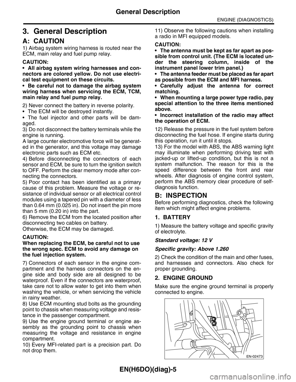
2. ENGINE GROUND
Make sure the engine ground terminal is properly
connected to engine.
EN-02473