2009 SUBARU TRIBECA warning
[x] Cancel search: warningPage 1020 of 2453
VDC(diag)-28
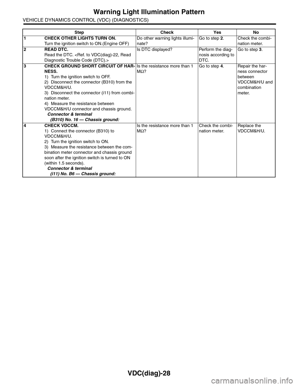
Warning Light Illumination Pattern
VEHICLE DYNAMICS CONTROL (VDC) (DIAGNOSTICS)
Step Check Yes No
1CHECK OTHER LIGHTS TURN ON.
Tu r n t h e i g n i t i o n s w i t c h t o O N . ( E n g i n e O F F )
Do other warning lights illumi-
nate?
Go to step 2.Check the combi-
nation meter.
2READ DTC.
Read the DTC.
Is DTC displayed? Perform the diag-
nosis according to
DTC.
Go to step 3.
3CHECK GROUND SHORT CIRCUIT OF HAR-
NESS.
1) Turn the ignition switch to OFF.
2) Disconnect the connector (B310) from the
VDCCM&H/U.
3) Disconnect the connector (i11) from combi-
nation meter.
4) Measure the resistance between
VDCCM&H/U connector and chassis ground.
Connector & terminal
(B310) No. 16 — Chassis ground:
Is the resistance more than 1
MΩ?
Go to step 4.Repair the har-
ness connector
between
VDCCM&H/U and
combination
meter.
4CHECK VDCCM.
1) Connect the connector (B310) to
VDCCM&H/U.
2) Turn the ignition switch to ON.
3) Measure the resistance between the com-
bination meter connector and chassis ground
soon after the ignition switch is turned to ON
(within 1.5 seconds).
Connector & terminal
(i11) No. B6 — Chassis ground:
Is the resistance more than 1
MΩ?
Check the combi-
nation meter.
Replace the
VDCCM&H/U.
Page 1021 of 2453
VDC(diag)-29
Warning Light Illumination Pattern
VEHICLE DYNAMICS CONTROL (VDC) (DIAGNOSTICS)
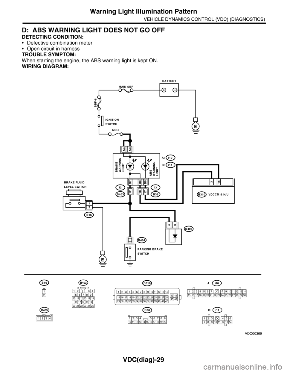
D: ABS WARNING LIGHT DOES NOT GO OFF
DETECTING CONDITION:
•Defective combination meter
•Open circuit in harness
TROUBLE SYMPTOM:
When starting the engine, the ABS warning light is kept ON.
WIRING DIAGRAM:
B16
12
B38
E
MAIN SBF
SBF-6
E
NO.5
B16
B404
A3A4
12
34B405
1234 5678910 11 12 13 14 15 16 17 18 19 20
BATTERY
IGNITIONSWITCH
BRAKE FLUIDLEVEL SWITCH
PARKING BRAKESWITCH
BRAKEWARNINGLIGHTABSWARNINGLIGHT
316
B310B38
i3
i10A:
i11B:
VDCCM & H/U
B8
1817B403
i2B7B6
VDC00369
12
B405
1234
B403
567821943
10
2422 23 25
1112131415161718192021
B310
1234
1516171819202122232425262728293031323334353637383940414245464344568910 11 12 13 147
1234567891011121314
i11B:
123456789101112131415161718192021222324252627282930
i10A:
Page 1022 of 2453
VDC(diag)-30
Warning Light Illumination Pattern
VEHICLE DYNAMICS CONTROL (VDC) (DIAGNOSTICS)
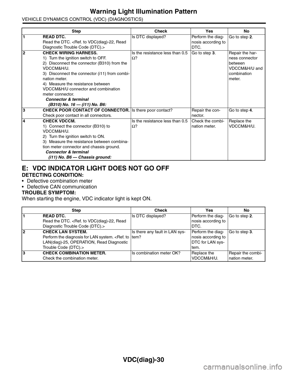
E: VDC INDICATOR LIGHT DOES NOT GO OFF
DETECTING CONDITION:
•Defective combination meter
•Defective CAN communication
TROUBLE SYMPTOM:
When starting the engine, VDC indicator light is kept ON.
Step Check Yes No
1READ DTC.
Read the DTC.
Is DTC displayed? Perform the diag-
nosis according to
DTC.
Go to step 2.
2CHECK WIRING HARNESS.
1) Turn the ignition switch to OFF.
2) Disconnect the connector (B310) from the
VDCCM&H/U.
3) Disconnect the connector (i11) from combi-
nation meter.
4) Measure the resistance between
VDCCM&H/U connector and combination
meter connector.
Connector & terminal
(B310) No. 16 — (i11) No. B6:
Is the resistance less than 0.5
Ω?
Go to step 3.Repair the har-
ness connector
between
VDCCM&H/U and
combination
meter.
3CHECK POOR CONTACT OF CONNECTOR.
Check poor contact in all connectors.
Is there poor contact? Repair the con-
nector.
Go to step 4.
4CHECK VDCCM.
1) Connect the connector (B310) to
VDCCM&H/U.
2) Turn the ignition switch to ON.
3) Measure the resistance between combina-
tion meter connector and chassis ground.
Connector & terminal
(i11) No. B6 — Chassis ground:
Is the resistance less than 0.5
Ω?
Check the combi-
nation meter.
Replace the
VDCCM&H/U.
Step Check Yes No
1READ DTC.
Read the DTC.
Is DTC displayed? Perform the diag-
nosis according to
DTC.
Go to step 2.
2CHECK LAN SYSTEM.
Perfor m the diagnosis for LAN system.
Tr o u b l e C o d e ( D T C ) . >
Is there any fault in LAN sys-
tem?
Pe r for m t h e d ia g -
nosis according to
DTC for LAN sys-
tem.
Go to step 3.
3CHECK COMBINATION METER.
Check the combination meter.
Is combination meter OK? Replace the
VDCCM&H/U.
Repair the combi-
nation meter.
Page 1023 of 2453
VDC(diag)-31
Warning Light Illumination Pattern
VEHICLE DYNAMICS CONTROL (VDC) (DIAGNOSTICS)
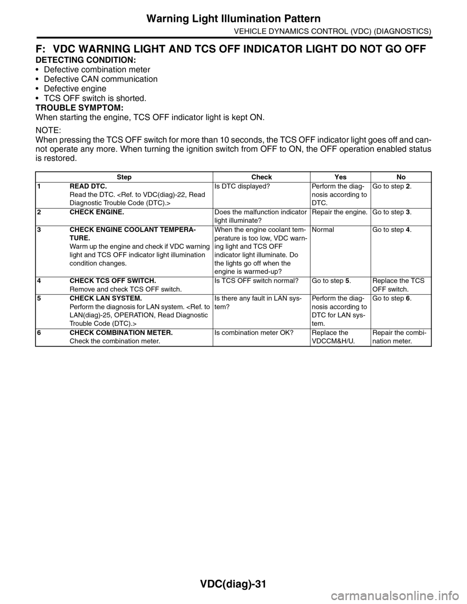
F: VDC WARNING LIGHT AND TCS OFF INDICATOR LIGHT DO NOT GO OFF
DETECTING CONDITION:
•Defective combination meter
•Defective CAN communication
•Defective engine
•TCS OFF switch is shorted.
TROUBLE SYMPTOM:
When starting the engine, TCS OFF indicator light is kept ON.
NOTE:
When pressing the TCS OFF switch for more than 10 seconds, the TCS OFF indicator light goes off and can-
not operate any more. When turning the ignition switch from OFF to ON, the OFF operation enabled status
is restored.
Step Check Yes No
1READ DTC.
Read the DTC.
Is DTC displayed? Perform the diag-
nosis according to
DTC.
Go to step 2.
2CHECK ENGINE.Does the malfunction indicator
light illuminate?
Repair the engine. Go to step 3.
3CHECK ENGINE COOLANT TEMPERA-
TURE.
War m up the engine and check if VDC war ning
light and TCS OFF indicator light illumination
condition changes.
When the engine coolant tem-
perature is too low, VDC warn-
ing light and TCS OFF
indicator light illuminate. Do
the lights go off when the
engine is warmed-up?
Normal Go to step 4.
4CHECK TCS OFF SWITCH.
Remove and check TCS OFF switch.
Is TCS OFF switch normal? Go to step 5.Replace the TCS
OFF switch.
5CHECK LAN SYSTEM.
Perfor m the diagnosis for LAN system.
Tr o u b l e C o d e ( D T C ) . >
Is there any fault in LAN sys-
tem?
Pe r for m t h e d ia g -
nosis according to
DTC for LAN sys-
tem.
Go to step 6.
6CHECK COMBINATION METER.
Check the combination meter.
Is combination meter OK? Replace the
VDCCM&H/U.
Repair the combi-
nation meter.
Page 1024 of 2453
VDC(diag)-32
Warning Light Illumination Pattern
VEHICLE DYNAMICS CONTROL (VDC) (DIAGNOSTICS)
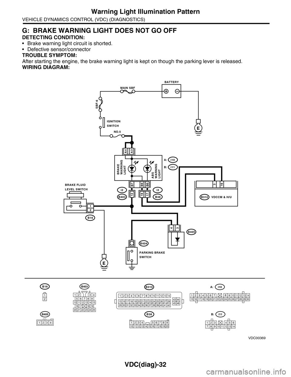
G: BRAKE WARNING LIGHT DOES NOT GO OFF
DETECTING CONDITION:
•Brake warning light circuit is shorted.
•Defective sensor/connector
TROUBLE SYMPTOM:
After starting the engine, the brake warning light is kept on though the parking lever is released.
WIRING DIAGRAM:
B16
12
B38
E
MAIN SBF
SBF-6
E
NO.5
B16
B404
A3A4
12
34B405
1234 5678910 11 12 13 14 15 16 17 18 19 20
BATTERY
IGNITIONSWITCH
BRAKE FLUIDLEVEL SWITCH
PARKING BRAKESWITCH
BRAKEWARNINGLIGHTABSWARNINGLIGHT
316
B310B38
i3
i10A:
i11B:
VDCCM & H/U
B8
1817B403
i2B7B6
VDC00369
12
B405
1234
B403
567821943
10
2422 23 25
1112131415161718192021
B310
1234
1516171819202122232425262728293031323334353637383940414245464344568910 11 12 13 147
1234567891011121314
i11B:
123456789101112131415161718192021222324252627282930
i10A:
Page 1025 of 2453
VDC(diag)-33
Warning Light Illumination Pattern
VEHICLE DYNAMICS CONTROL (VDC) (DIAGNOSTICS)
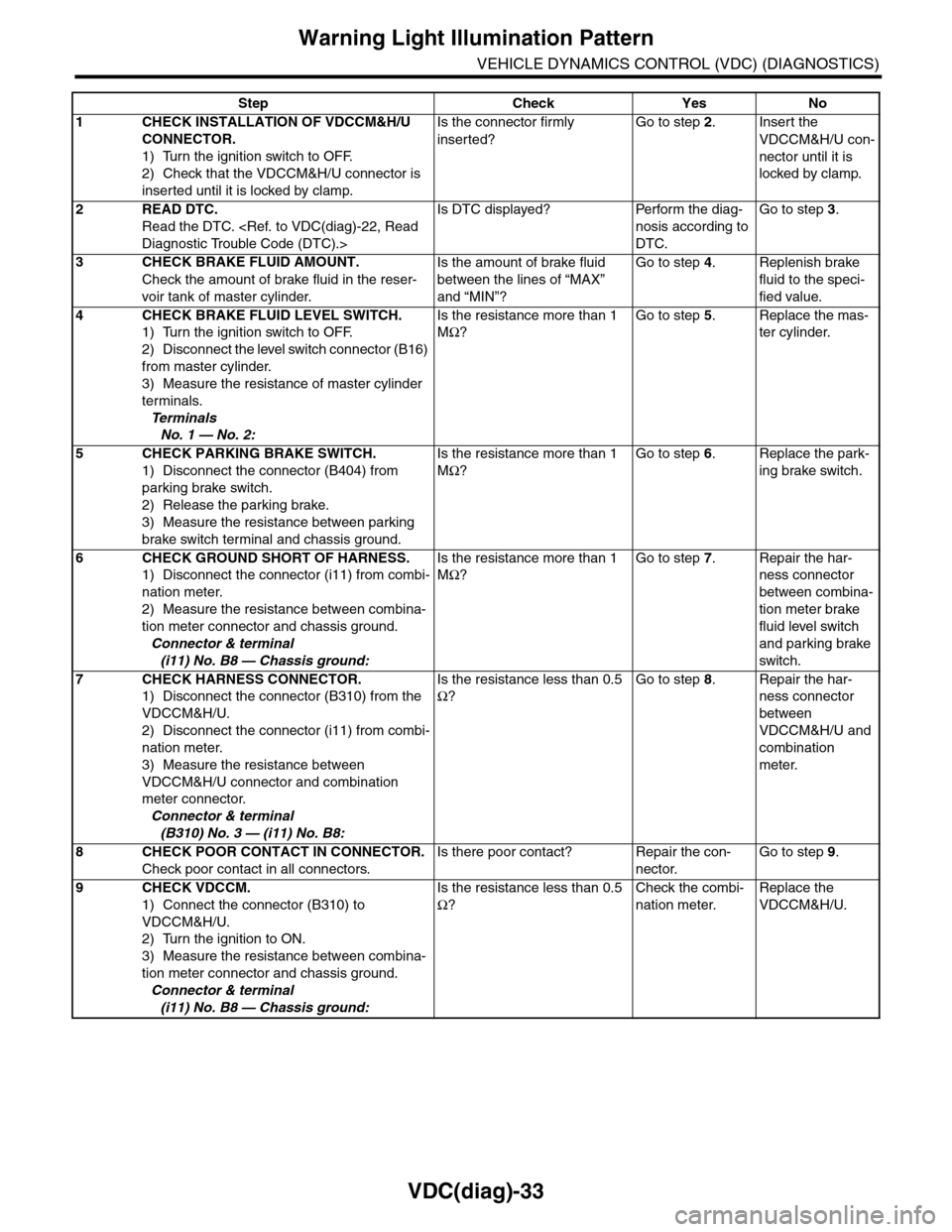
Step Check Yes No
1CHECK INSTALLATION OF VDCCM&H/U
CONNECTOR.
1) Turn the ignition switch to OFF.
2) Check that the VDCCM&H/U connector is
inserted until it is locked by clamp.
Is the connector firmly
inserted?
Go to step 2.Insert the
VDCCM&H/U con-
nector until it is
locked by clamp.
2READ DTC.
Read the DTC.
Is DTC displayed? Perform the diag-
nosis according to
DTC.
Go to step 3.
3CHECK BRAKE FLUID AMOUNT.
Check the amount of brake fluid in the reser-
voir tank of master cylinder.
Is the amount of brake fluid
between the lines of “MAX”
and “MIN”?
Go to step 4.Replenish brake
fluid to the speci-
fied value.
4CHECK BRAKE FLUID LEVEL SWITCH.
1) Turn the ignition switch to OFF.
2) Disconnect the level switch connector (B16)
from master cylinder.
3) Measure the resistance of master cylinder
terminals.
Te r m i n a l s
No. 1 — No. 2:
Is the resistance more than 1
MΩ?
Go to step 5.Replace the mas-
ter cylinder.
5CHECK PARKING BRAKE SWITCH.
1) Disconnect the connector (B404) from
parking brake switch.
2) Release the parking brake.
3) Measure the resistance between parking
brake switch terminal and chassis ground.
Is the resistance more than 1
MΩ?
Go to step 6.Replace the park-
ing brake switch.
6CHECK GROUND SHORT OF HARNESS.
1) Disconnect the connector (i11) from combi-
nation meter.
2) Measure the resistance between combina-
tion meter connector and chassis ground.
Connector & terminal
(i11) No. B8 — Chassis ground:
Is the resistance more than 1
MΩ?
Go to step 7.Repair the har-
ness connector
between combina-
tion meter brake
fluid level switch
and parking brake
switch.
7CHECK HARNESS CONNECTOR.
1) Disconnect the connector (B310) from the
VDCCM&H/U.
2) Disconnect the connector (i11) from combi-
nation meter.
3) Measure the resistance between
VDCCM&H/U connector and combination
meter connector.
Connector & terminal
(B310) No. 3 — (i11) No. B8:
Is the resistance less than 0.5
Ω?
Go to step 8.Repair the har-
ness connector
between
VDCCM&H/U and
combination
meter.
8CHECK POOR CONTACT IN CONNECTOR.
Check poor contact in all connectors.
Is there poor contact? Repair the con-
nector.
Go to step 9.
9CHECK VDCCM.
1) Connect the connector (B310) to
VDCCM&H/U.
2) Turn the ignition to ON.
3) Measure the resistance between combina-
tion meter connector and chassis ground.
Connector & terminal
(i11) No. B8 — Chassis ground:
Is the resistance less than 0.5
Ω?
Check the combi-
nation meter.
Replace the
VDCCM&H/U.
Page 1037 of 2453
VDC(diag)-45
Diagnostic Procedure with Diagnostic Trouble Code (DTC)
VEHICLE DYNAMICS CONTROL (VDC) (DIAGNOSTICS)
M: DTC C0031 FRONT INLET SOLENOID VALVE RH MALFUNCTION IN VDC-
CM&H/U
NOTE:
For the diagnostic procedure, refer to DTC C0063 “LINEAR VALVE MALFUNCTION IN VDCCM&H/U”.
N: DTC C0032 FRONT OUTLET SOLENOID VALVE RH MALFUNCTION IN VDC-
CM&H/U
NOTE:
For the diagnostic procedure, refer to DTC C0063 “LINEAR VALVE MALFUNCTION IN VDCCM&H/U”.
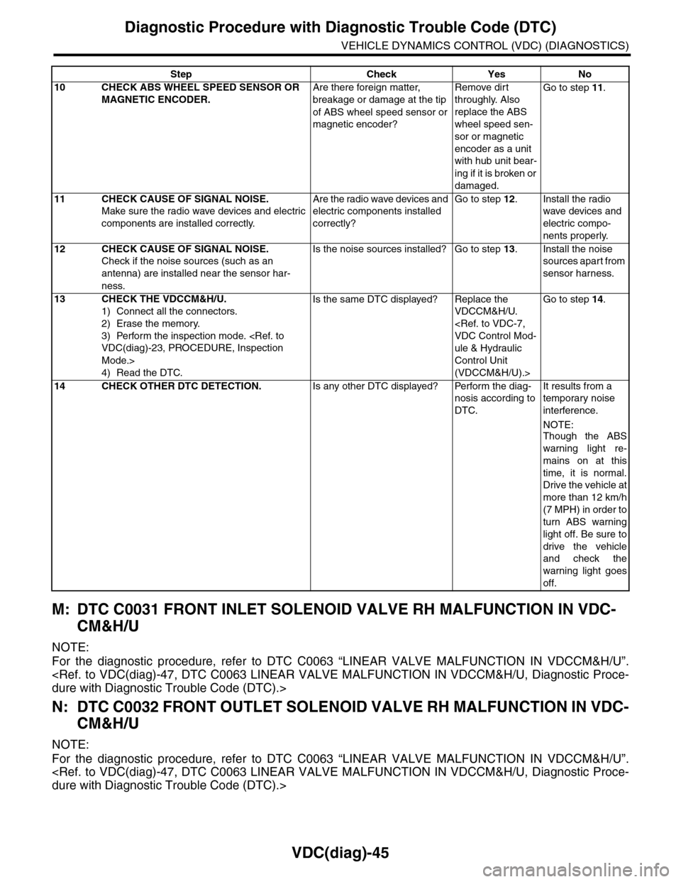
10 CHECK ABS WHEEL SPEED SENSOR OR
MAGNETIC ENCODER.
Are there foreign matter,
breakage or damage at the tip
of ABS wheel speed sensor or
magnetic encoder?
Remove dirt
throughly. Also
replace the ABS
wheel speed sen-
sor or magnetic
encoder as a unit
with hub unit bear-
ing if it is broken or
damaged.
Go to step 11.
11 CHECK CAUSE OF SIGNAL NOISE.
Make sure the radio wave devices and electric
components are installed correctly.
Are the radio wave devices and
electric components installed
correctly?
Go to step 12.Install the radio
wave devices and
electric compo-
nents properly.
12 CHECK CAUSE OF SIGNAL NOISE.
Check if the noise sources (such as an
antenna) are installed near the sensor har-
ness.
Is the noise sources installed? Go to step 13.Install the noise
sources apart from
sensor harness.
13 CHECK THE VDCCM&H/U.
1) Connect all the connectors.
2) Erase the memory.
3) Perform the inspection mode.
Mode.>
4) Read the DTC.
Is the same DTC displayed? Replace the
VDCCM&H/U.
ule & Hydraulic
Control Unit
(VDCCM&H/U).>
Go to step 14.
14 CHECK OTHER DTC DETECTION.Is any other DTC displayed? Perform the diag-
nosis according to
DTC.
It results from a
temporary noise
interference.
NOTE:
Though the ABS
warning light re-
mains on at this
time, it is normal.
Drive the vehicle at
more than 12 km/h
(7 MPH) in order to
turn ABS warning
light off. Be sure to
drive the vehicle
and check the
warning light goes
off.
Step Check Yes No
Page 1041 of 2453
VDC(diag)-49
Diagnostic Procedure with Diagnostic Trouble Code (DTC)
VEHICLE DYNAMICS CONTROL (VDC) (DIAGNOSTICS)
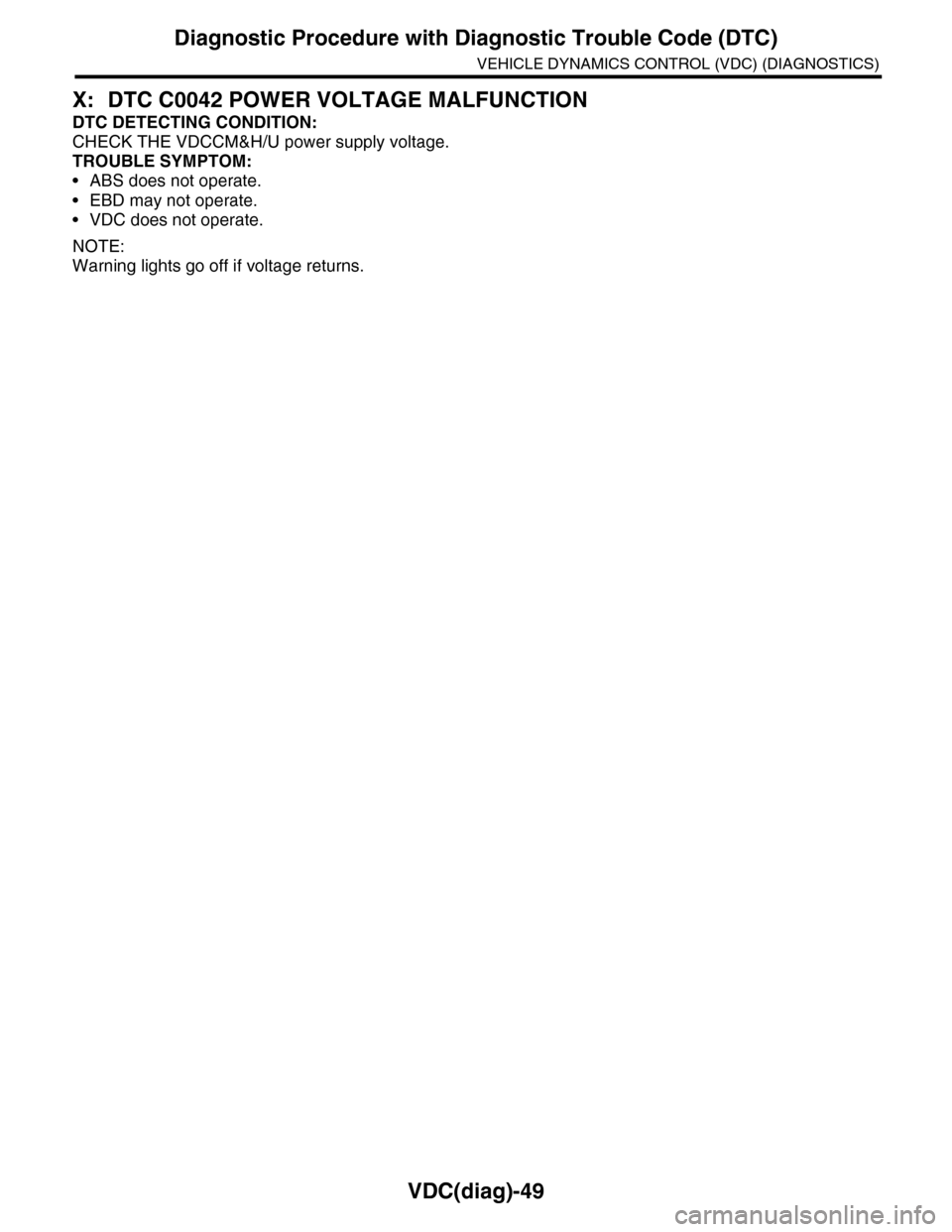
X: DTC C0042 POWER VOLTAGE MALFUNCTION
DTC DETECTING CONDITION:
CHECK THE VDCCM&H/U power supply voltage.
TROUBLE SYMPTOM:
•ABS does not operate.
•EBD may not operate.
•VDC does not operate.
NOTE:
Warning lights go off if voltage returns.