Page 1607 of 2453
FU(H6DO)-46
Fuel Sub Level Sensor
FUEL INJECTION (FUEL SYSTEMS)
26.Fuel Sub Level Sensor
A: REMOVAL
WARNING:
•Place “NO FIRE” signs near the working area.
•Be careful not to spill fuel on the floor.
1) Drain fuel.
FUEL, PROCEDURE, Fuel.>
2) Remove the second seat.
MOVAL, Second-row Seats.>
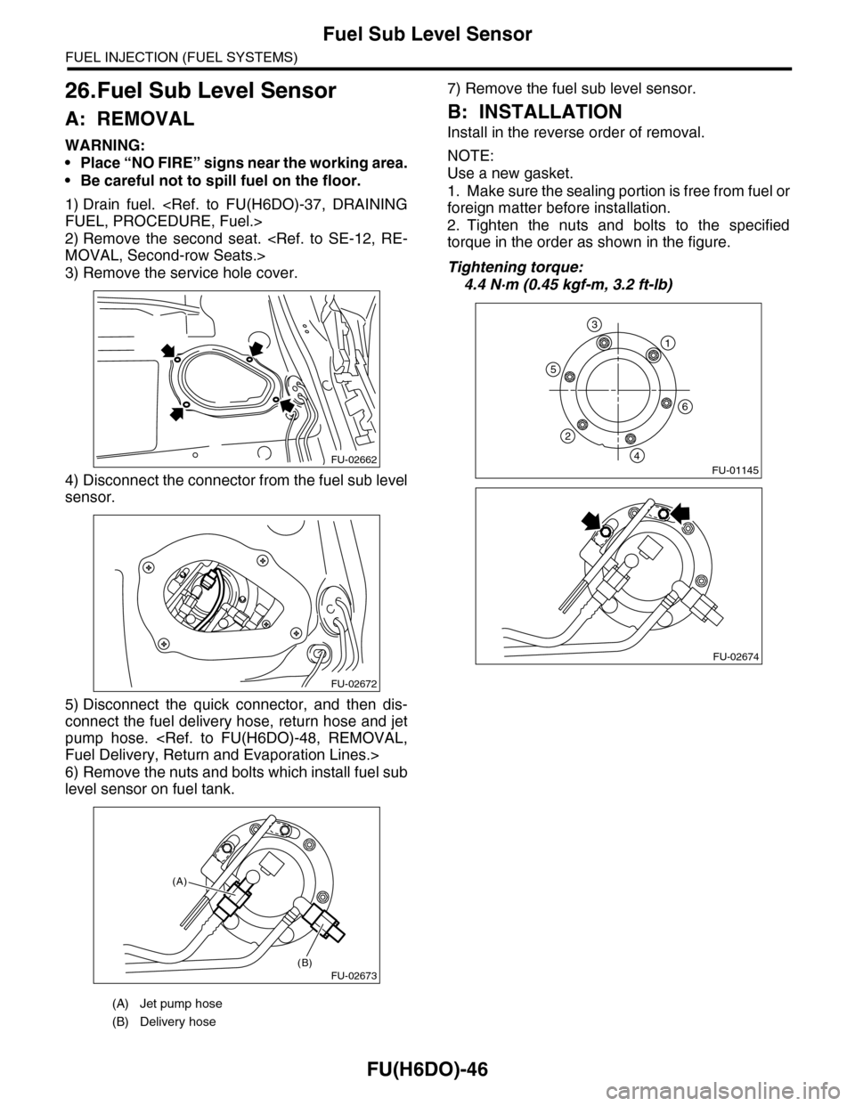
3) Remove the service hole cover.
4) Disconnect the connector from the fuel sub level
sensor.
5) Disconnect the quick connector, and then dis-
connect the fuel delivery hose, return hose and jet
pump hose.
Fuel Delivery, Return and Evaporation Lines.>
6) Remove the nuts and bolts which install fuel sub
level sensor on fuel tank.
7) Remove the fuel sub level sensor.
B: INSTALLATION
Install in the reverse order of removal.
NOTE:
Use a new gasket.
1. Make sure the sealing portion is free from fuel or
foreign matter before installation.
2. Tighten the nuts and bolts to the specified
torque in the order as shown in the figure.
Tightening torque:
4.4 N·m (0.45 kgf-m, 3.2 ft-lb)
(A) Jet pump hose
(B) Delivery hose
FU-02662
FU-02672
FU-02673(B)
(A)
FU-01145
1
6
5
2
4
3
FU-02674
Page 1609 of 2453
FU(H6DO)-48
Fuel Delivery, Return and Evaporation Lines
FUEL INJECTION (FUEL SYSTEMS)
28.Fuel Delivery, Return and Evaporation Lines
A: REMOVAL
1) Set the vehicle on a lift.
2) Release the fuel pressure.
Fuel.>
3) Open the fuel filler flap lid, and remove the fuel filler cap.
4) Remove the floor mat.
5) Disconnect the fuel delivery pipe and hose and the evaporation pipe and hose.
6) In the engine compartment, disconnect the fuel
delivery hoses and evaporation hose.
(1) Disconnect the quick connector of the fuel
delivery line by pushing the ST in the direction
of the arrow.
ST 42099AE000 CONNECTOR REMOVER
(2) Remove the clip, and disconnect the evapo-
ration hose from the pipe.
WARNING:
•Be careful not to spill fuel.
•Catch the fuel from hoses using a container
or cloth.
7) Lift-up the vehicle.
8) Remove the fuel tank.
REMOVAL, Fuel Tank.>
FU-02675
Page 1782 of 2453
GD(H6DO)-170
Diagnostic Trouble Code (DTC) Detecting Criteria
GENERAL DESCRIPTION
CX:DTC P0600 SERIAL COMMUNICATION LINK
1. OUTLINE OF DIAGNOSIS
Detect malfunction of CAN communication.
When CAN communications is not possible, and CAN communications with AT is not possible, judge as NG
if data from the AT is not normal.
2. COMPONENT DESCRIPTION
ECM and TCM are connected by high speed CAN.
(Common Specifications)
CAN Protocol 2.0 B (Active)
Frame Format: 11 Bit ID Frame (Standard Frame)
(High Speed CAN)
Conforms to ISO11898
Communication Speed: 500 kbps
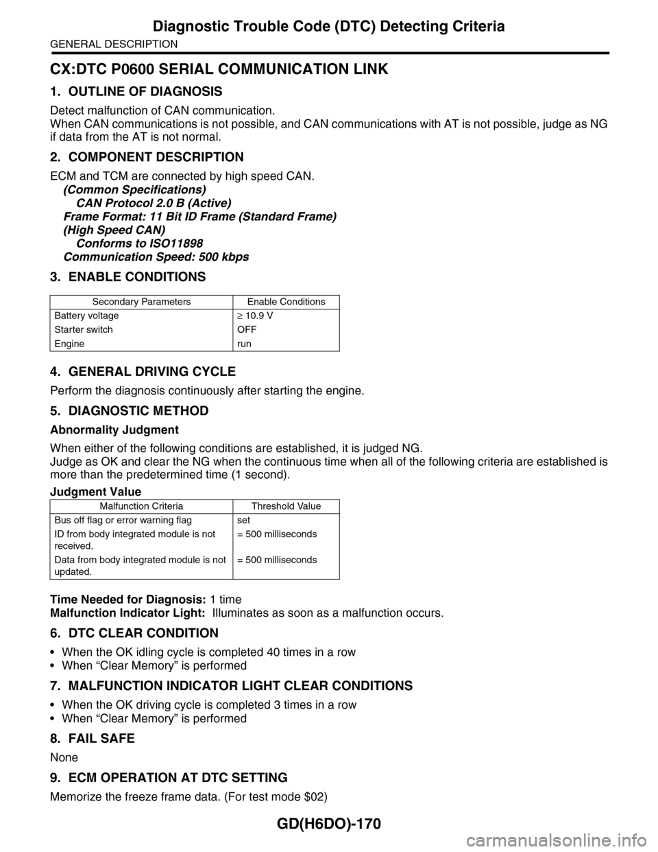
3. ENABLE CONDITIONS
4. GENERAL DRIVING CYCLE
Perform the diagnosis continuously after starting the engine.
5. DIAGNOSTIC METHOD
Abnormality Judgment
When either of the following conditions are established, it is judged NG.
Judge as OK and clear the NG when the continuous time when all of the following criteria are established is
more than the predetermined time (1 second).
Time Needed for Diagnosis: 1 time
Malfunction Indicator Light: Illuminates as soon as a malfunction occurs.
6. DTC CLEAR CONDITION
•When the OK idling cycle is completed 40 times in a row
•When “Clear Memory” is performed
7. MALFUNCTION INDICATOR LIGHT CLEAR CONDITIONS
•When the OK driving cycle is completed 3 times in a row
•When “Clear Memory” is performed
8. FAIL SAFE
None
9. ECM OPERATION AT DTC SETTING
Memorize the freeze frame data. (For test mode $02)
Secondary Parameters Enable Conditions
Battery voltage≥ 10.9 V
Starter switch OFF
Engine run
Judgment Value
Malfunction Criteria Threshold Value
Bus off flag or error warning flag set
ID from body integrated module is not
received.
= 500 milliseconds
Data from body integrated module is not
updated.
= 500 milliseconds
Page 1855 of 2453
LU(H6DO)-6
Oil Pressure System
LUBRICATION
B: INSPECTION
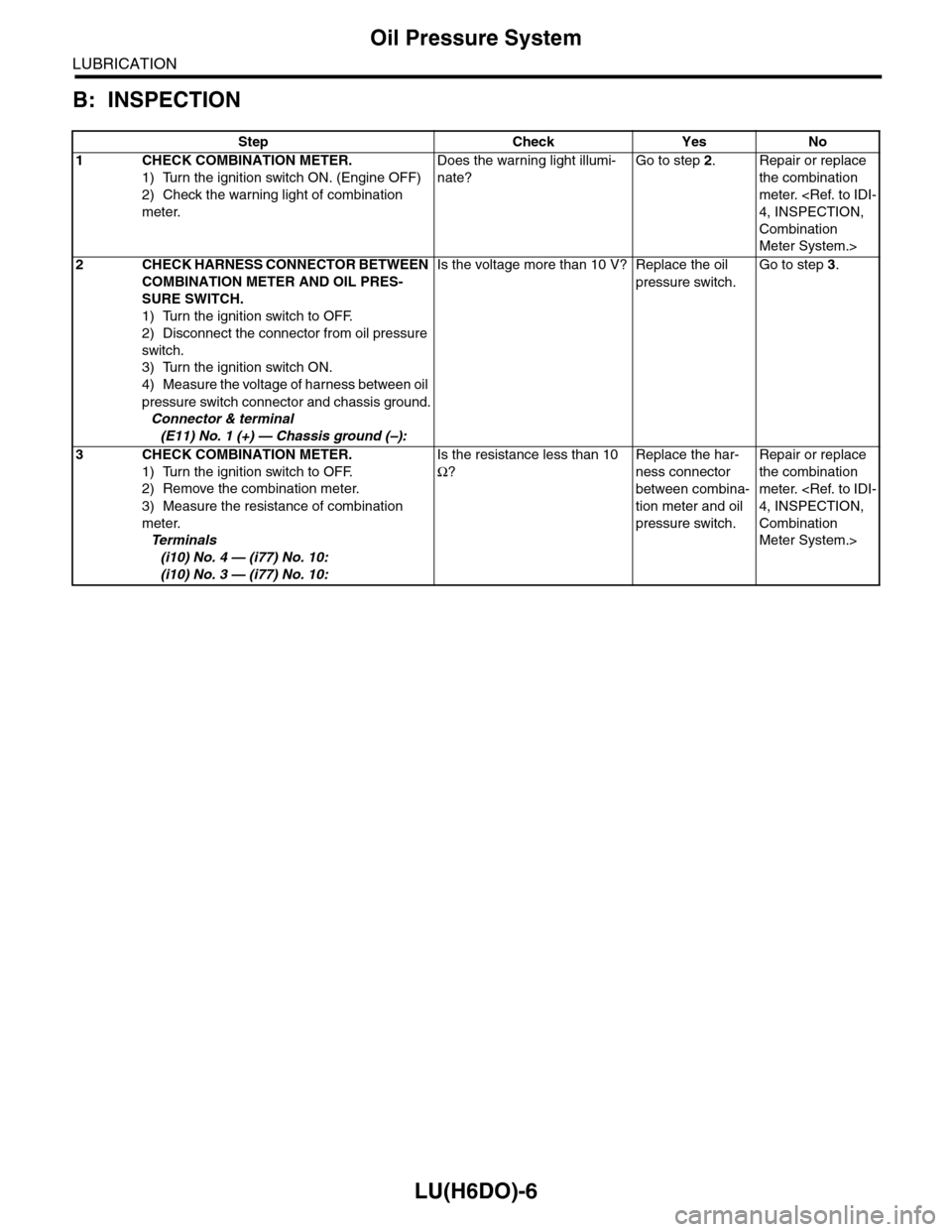
Step Check Yes No
1CHECK COMBINATION METER.
1) Turn the ignition switch ON. (Engine OFF)
2) Check the warning light of combination
meter.
Does the warning light illumi-
nate?
Go to step 2.Repair or replace
the combination
meter.
4, INSPECTION,
Combination
Meter System.>
2CHECK HARNESS CONNECTOR BETWEEN
COMBINATION METER AND OIL PRES-
SURE SWITCH.
1) Turn the ignition switch to OFF.
2) Disconnect the connector from oil pressure
switch.
3) Turn the ignition switch ON.
4) Measure the voltage of harness between oil
pressure switch connector and chassis ground.
Connector & terminal
(E11) No. 1 (+) — Chassis ground (–):
Is the voltage more than 10 V? Replace the oil
pressure switch.
Go to step 3.
3CHECK COMBINATION METER.
1) Turn the ignition switch to OFF.
2) Remove the combination meter.
3) Measure the resistance of combination
meter.
Te r m i n a l s
(i10) No. 4 — (i77) No. 10:
(i10) No. 3 — (i77) No. 10:
Is the resistance less than 10
Ω?
Replace the har-
ness connector
between combina-
tion meter and oil
pressure switch.
Repair or replace
the combination
meter.
4, INSPECTION,
Combination
Meter System.>
Page 1866 of 2453
LU(H6DO)-17
General Diagnostics Table
LUBRICATION
10.General Diagnostics Table
A: INSPECTION
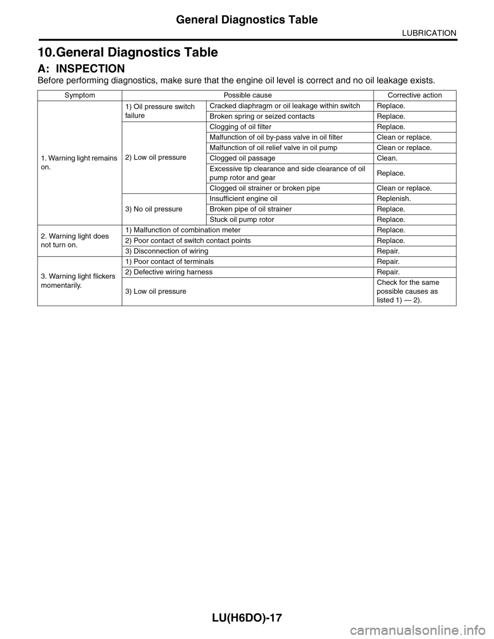
Before performing diagnostics, make sure that the engine oil level is correct and no oil leakage exists.
Symptom Possible cause Corrective action
1. Warning light remains
on.
1) Oil pressure switch
failure
Cracked diaphragm or oil leakage within switch Replace.
Broken spring or seized contacts Replace.
2) Low oil pressure
Clogging of oil filter Replace.
Malfunction of oil by-pass valve in oil filter Clean or replace.
Malfunction of oil relief valve in oil pump Clean or replace.
Clogged oil passage Clean.
Excessive tip clearance and side clearance of oil
pump rotor and gearReplace.
Clogged oil strainer or broken pipe Clean or replace.
3) No oil pressure
Insufficient engine oil Replenish.
Broken pipe of oil strainer Replace.
Stuck oil pump rotor Replace.
2. Warning light does
not turn on.
1) Malfunction of combination meter Replace.
2) Poor contact of switch contact points Replace.
3) Disconnection of wiring Repair.
3. Warning light flickers
momentarily.
1) Poor contact of terminals Repair.
2) Defective wiring harness Repair.
3) Low oil pressure
Check for the same
possible causes as
listed 1) — 2).
Page 1891 of 2453
ME(H6DO)-25
Engine Oil Pressure
MECHANICAL
6. Engine Oil Pressure
A: INSPECTION
1) Remove the oil pressure switch from cylinder
block.
Pressure Switch.>
2) Connect the oil pressure gauge hose to cylinder
block.
3) Connect the ground cable to the battery.
4) Start the engine, and measure the oil pressure.
OIL PRESSURE (at oil temperature of 80°C
(176°F)):
Standard:
135 kPa (1.4 kgf/cm2, 20 psi) or more (at
600 rpm)
500 kPa (5.1 kgf/cm2, 73 psi) or more (at
5,000 rpm)
CAUTION:
•If the oil pressure is out of specification,
check oil pump, oil filter and lubrication line.
Diagnostics Table.>
•If the oil pressure warning light is turned ON
and oil pressure is in specification, replace the
oil pressure switch.
SPECTION, General Diagnostics Table.>
5) After measuring the oil pressure, install the oil
pressure switch.
LATION, Oil Pressure Switch.>
Tightening torque:
25 N·m (2.5 kgf-m, 18 ft-lb)
Page 1892 of 2453
ME(H6DO)-26
Fuel Pressure
MECHANICAL
7. Fuel Pressure
A: INSPECTION
WARNING:
Before removing the fuel pressure gauge, re-
lease the fuel pressure.
1) Release the fuel pressure.
PRESSURE, PROCEDURE, Fuel.>
2) Disconnect the fuel delivery hose and connect
fuel pressure gauge.
(1) Disconnect the fuel delivery hose using the
ST1.
ST1 42099AE000 CONNECTOR REMOVER
(2) Connect the fuel pressure meter using the
ST2 and ST3.
NOTE:
ST2 is a genuine Subaru part.
ST2 42075AG690 FUEL HOSE
ST3 18471AA000 FUEL PIPE ADAPTER
3) Install the fuse of fuel pump to main fuse box.
4) Start the engine.
5) Measure the fuel pressure after warming up the
engine.
Fuel pressure:
Standard: 338 — 348 kPa (3.4 — 3.5 kgf/cm2,
49 — 50.5 psi)
NOTE:
The fuel pressure gauge registers 10 to 20 kPa (0.1
to 0.2 kgf/cm2, 1 to 3 psi) higher than standard val-
ues during high-altitude operations.
(A) ST 2
(B) ST 3
ME-02666
(A)
(B)
FU-01122
Page 1983 of 2453
SC(H6DO)-25
Battery
STARTING/CHARGING SYSTEMS
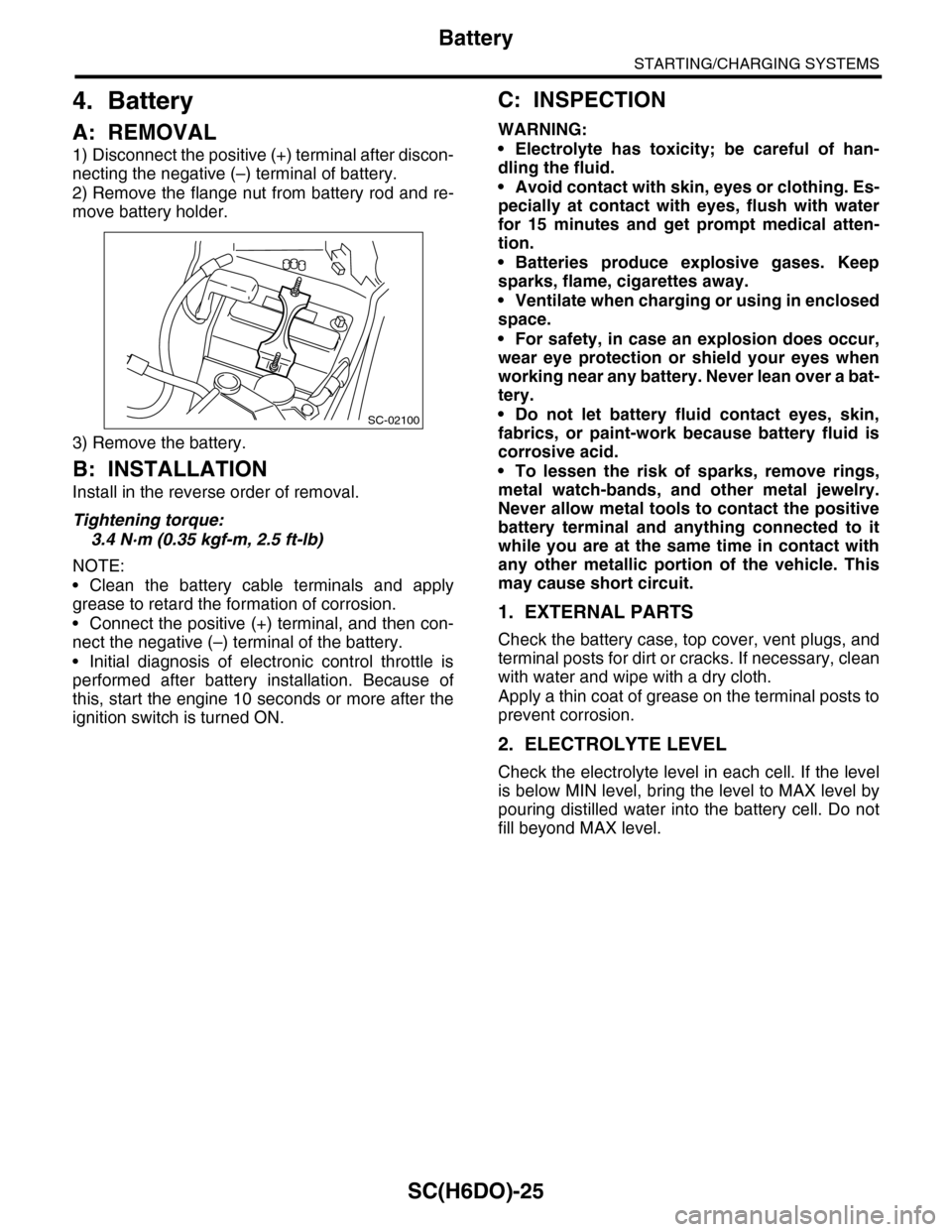
4. Battery
A: REMOVAL
1) Disconnect the positive (+) terminal after discon-
necting the negative (–) terminal of battery.
2) Remove the flange nut from battery rod and re-
move battery holder.
3) Remove the battery.
B: INSTALLATION
Install in the reverse order of removal.
Tightening torque:
3.4 N·m (0.35 kgf-m, 2.5 ft-lb)
NOTE:
•Clean the battery cable terminals and apply
grease to retard the formation of corrosion.
•Connect the positive (+) terminal, and then con-
nect the negative (–) terminal of the battery.
•Initial diagnosis of electronic control throttle is
performed after battery installation. Because of
this, start the engine 10 seconds or more after the
ignition switch is turned ON.
C: INSPECTION
WARNING:
•Electrolyte has toxicity; be careful of han-
dling the fluid.
•Avoid contact with skin, eyes or clothing. Es-
pecially at contact with eyes, flush with water
for 15 minutes and get prompt medical atten-
tion.
•Batteries produce explosive gases. Keep
sparks, flame, cigarettes away.
•Ventilate when charging or using in enclosed
space.
•For safety, in case an explosion does occur,
wear eye protection or shield your eyes when
working near any battery. Never lean over a bat-
tery.
•Do not let battery fluid contact eyes, skin,
fabrics, or paint-work because battery fluid is
corrosive acid.
•To lessen the risk of sparks, remove rings,
metal watch-bands, and other metal jewelry.
Never allow metal tools to contact the positive
battery terminal and anything connected to it
while you are at the same time in contact with
any other metallic portion of the vehicle. This
may cause short circuit.
1. EXTERNAL PARTS
Check the battery case, top cover, vent plugs, and
terminal posts for dirt or cracks. If necessary, clean
with water and wipe with a dry cloth.
Apply a thin coat of grease on the terminal posts to
prevent corrosion.
2. ELECTROLYTE LEVEL
Check the electrolyte level in each cell. If the level
is below MIN level, bring the level to MAX level by
pouring distilled water into the battery cell. Do not
fill beyond MAX level.
SC-02100