2009 SUBARU TRIBECA center console
[x] Cancel search: center consolePage 289 of 2453
EI-47
Floor Mat
EXTERIOR/INTERIOR TRIM
20.Floor Mat
A: REMOVAL
1. FRONT FLOOR MAT
1) Remove the front seats.
2) Remove the second–row seats.
3) Remove the console box.
4) Remove the instrument panel lower cover.
er.>
5) Remove the glove box.
6) Remove the following trims.
•Front door scuff plate
•Rear door scuff plate
•Front pillar lower trim
•Center pillar lower trim
7) Remove the remote opener cover.
8) Remove the navigation unit.
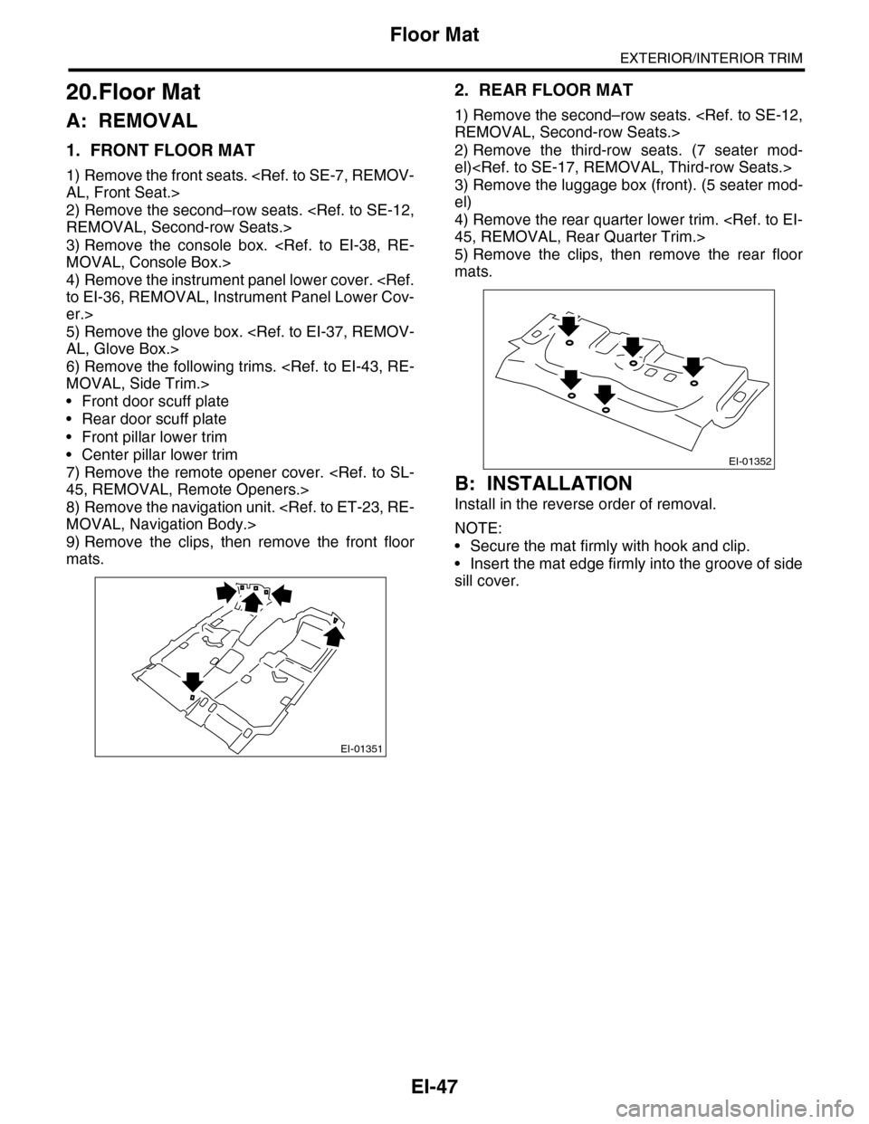
9) Remove the clips, then remove the front floor
mats.
2. REAR FLOOR MAT
1) Remove the second–row seats.
2) Remove the third-row seats. (7 seater mod-
el)
3) Remove the luggage box (front). (5 seater mod-
el)
4) Remove the rear quarter lower trim.
5) Remove the clips, then remove the rear floor
mats.
B: INSTALLATION
Install in the reverse order of removal.
NOTE:
•Secure the mat firmly with hook and clip.
•Insert the mat edge firmly into the groove of side
sill cover.
EI-01351
EI-01352
Page 380 of 2453

AC(diag)-3
General Description
HVAC SYSTEM (AUTO A/C) (DIAGNOSTICS)
2. General Description
A: CAUTION
1) Never connect the battery in reverse polarity.
•Auto A/C control module may be destroyed in-
stantly.
2) Do not disconnect the battery terminals while the
engine is running.
•A large counter electromotive force will be gener-
ated in the generator, and this voltage may damage
electronic parts such as auto A/C control module
etc.
3) Before disconnecting the connectors of each
sensor and the auto A/C control module, be sure to
turn the ignition switch to OFF.
•Auto A/C control module may be damaged.
4) Every A/C-related part is a precision part. Do not
drop them.
5) Airbag system wiring harness is routed near the
A/C control panel and junction box.
CAUTION:
•For airbag system, yellow-colored wiring har-
ness and connectors are all used. Do not use
the electrical test equipment on these circuits.
•Be careful not to damage the airbag system
wiring harness when servicing the A/C control
panel and junction box.
B: INSPECTION
Before performing the diagnosis, check the follow-
ing items which might affect A/C system problems.
1. BATTERY
1) Measure the battery voltage and specific gravity
of electrolyte.
Standard voltage: 12 V
Specific gravity: 1.260 or more
2) Check the condition of the fuses for A/C system
power supply and other fuses.
3) Check the condition of harness and harness
connector connections.
2. ASPIRATOR HOSE
1) Turn the ignition switch to ON, and press the A/
C switch.
2) Turn the temperature control dial to maximum
hot position.
3) Turn the air flow control dial to “DEF” position.
4) Turn the fan speed control dial to 4th position.
5) Put a strip of paper close to the front side of in-
vehicle sensor suction port (A) located in the driv-
er’s side console side panel, and check that air is
being sucked into the port by seeing the paper
moving towards the port.
NOTE:
Be careful not to let the paper get sucked into the
port.
6) If the paper does not move at all, remove the
driver’s side console side panel
connection of the aspirator hose, in-vehicle sensor
and heater unit, and repair them if necessary.
3. A/C LINE
Check the connection for A/C line (A) and lower
side high-pressure pipe.
AC-01323
AC-01324
(A)
Page 450 of 2453

IDI-11
Combination Meter
INSTRUMENTATION/DRIVER INFO
3. Combination Meter
A: REMOVAL
1) Disconnect the ground cable from battery.
2) Set the tilt steering at the lowest position.
3) Remove the console box.
4) Remove the control panel.
5) Remove the instrument panel lower cover.
er.>
6) Remove the console side panel.
7) Remove the meter hood.
8) Remove the screws of combination meter (two
for upper side, two for lower side) and pull the com-
bination meter.
9) Disconnect the connector in the rear side of
combination meter to remove meter.
CAUTION:
•Be careful not to damage the meter or instru-
ment panel.
•Pay particular attention to avoid damaging
the meter glass.
B: INSTALLATION
Install in the reverse order of removal.
CAUTION:
•Make sure the electrical connector is con-
nected securely.
•Make sure that each meter operates normally.
•When the combination meter of model with
immobilizer has been replaced, be sure to per-
form the registration of immobilizer.
ID-00189
Page 1099 of 2453
VDC-18
Yaw Rate & Lateral G Sensor
VEHICLE DYNAMICS CONTROL (VDC)
5. Yaw Rate & Lateral G Sensor
A: REMOVAL
1) Disconnect the ground cable from the battery.
2) Remove the console box.
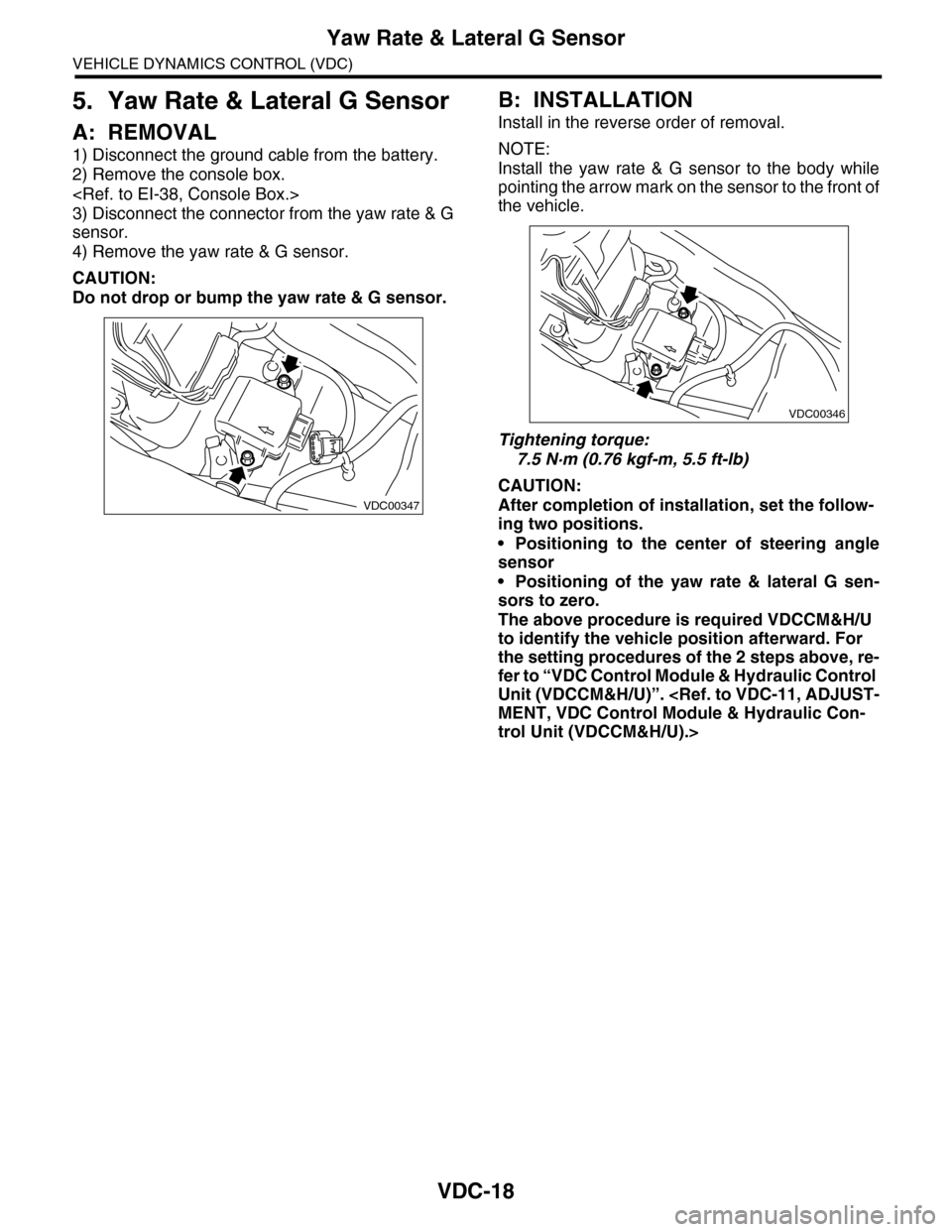
3) Disconnect the connector from the yaw rate & G
sensor.
4) Remove the yaw rate & G sensor.
CAUTION:
Do not drop or bump the yaw rate & G sensor.
B: INSTALLATION
Install in the reverse order of removal.
NOTE:
Install the yaw rate & G sensor to the body while
pointing the arrow mark on the sensor to the front of
the vehicle.
Tightening torque:
7.5 N·m (0.76 kgf-m, 5.5 ft-lb)
CAUTION:
After completion of installation, set the follow-
ing two positions.
•Positioning to the center of steering angle
sensor
•Positioning of the yaw rate & lateral G sen-
sors to zero.
The above procedure is required VDCCM&H/U
to identify the vehicle position afterward. For
the setting procedures of the 2 steps above, re-
fer to “VDC Control Module & Hydraulic Control
Unit (VDCCM&H/U)”.
trol Unit (VDCCM&H/U).>
VDC00347
VDC00346
Page 2271 of 2453
CS-19
Select Lever
CONTROL SYSTEMS
3. Select Lever
A: REMOVAL
1) Set the vehicle on a lift.
2) Disconnect the ground cable from battery.
3) Shift the select lever to “N” range.
4) Lift–up the vehicle.
5) Remove the rear exhaust pipe and muffler.
6) Remove the heat shield cover.
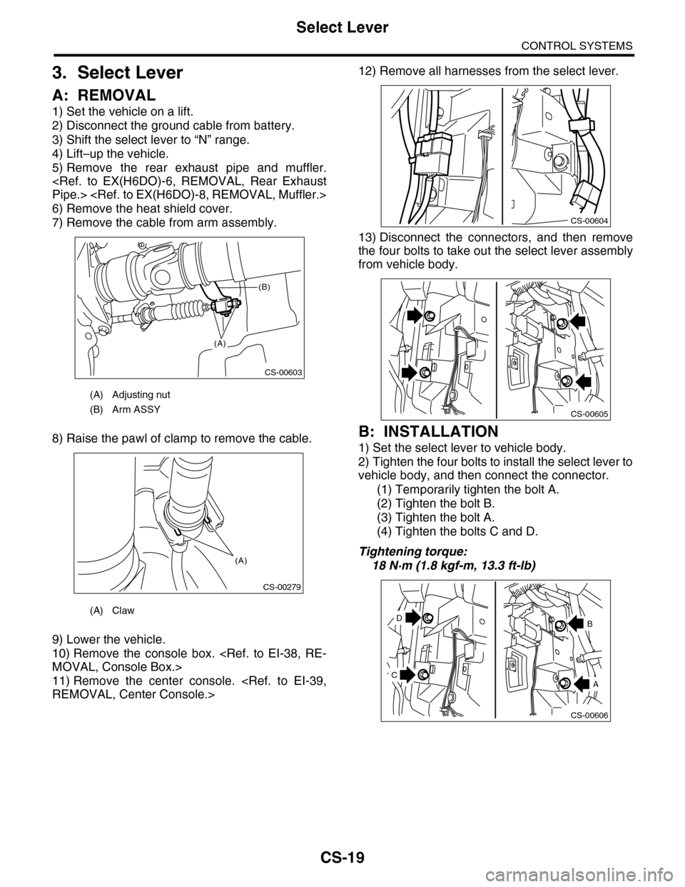
7) Remove the cable from arm assembly.
8) Raise the pawl of clamp to remove the cable.
9) Lower the vehicle.
10) Remove the console box.
11) Remove the center console.
12) Remove all harnesses from the select lever.
13) Disconnect the connectors, and then remove
the four bolts to take out the select lever assembly
from vehicle body.
B: INSTALLATION
1) Set the select lever to vehicle body.
2) Tighten the four bolts to install the select lever to
vehicle body, and then connect the connector.
(1) Temporarily tighten the bolt A.
(2) Tighten the bolt B.
(3) Tighten the bolt A.
(4) Tighten the bolts C and D.
Tightening torque:
18 N·m (1.8 kgf-m, 13.3 ft-lb)
(A) Adjusting nut
(B) Arm ASSY
(A) Claw
CS-00603
(A)
(B)
CS-00279
(A)
CS-00604
CS-00605
CS-00606
D
A
B
C
Page 2272 of 2453
CS-20
Select Lever
CONTROL SYSTEMS
3) Install the shift select cable onto select lever.
4) Install the center console.
5) Install the console box.
6) Shift the select lever to “N” range.
7) Lift–up the vehicle.
8) Shift the range select lever to the “N” range.
9) Secure the cable to the bracket.
10) Adjust the select cable position.
11) After the completion of adjustment, confirm that
the select lever operates properly at all range posi-
tions.
12) Install the heat shield cover.
13) Install the rear exhaust pipe and muffler.
Pipe.>
14) Inspect the following items. When a malfunc-
tion is found in the inspection, adjust the select ca-
ble.
(1) Engine starts when the select lever is in “P”
and “N” range, but not in other ranges.
(2) Back-up light illuminates when the select le-
ver is in the “R” range, but not in other ranges.
(3) Select lever and indicator positions are
matched.
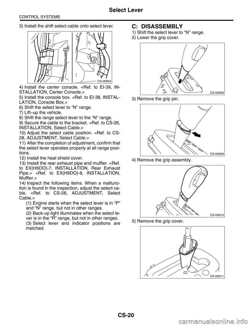
C: DISASSEMBLY
1) Shift the select lever to “N” range.
2) Lower the grip cover.
3) Remove the grip pin.
4) Remove the grip assembly.
5) Remove the grip cover.
CS-00604
CS-00608
CS-00609
CS-00610
CS-00611
Page 2448 of 2453
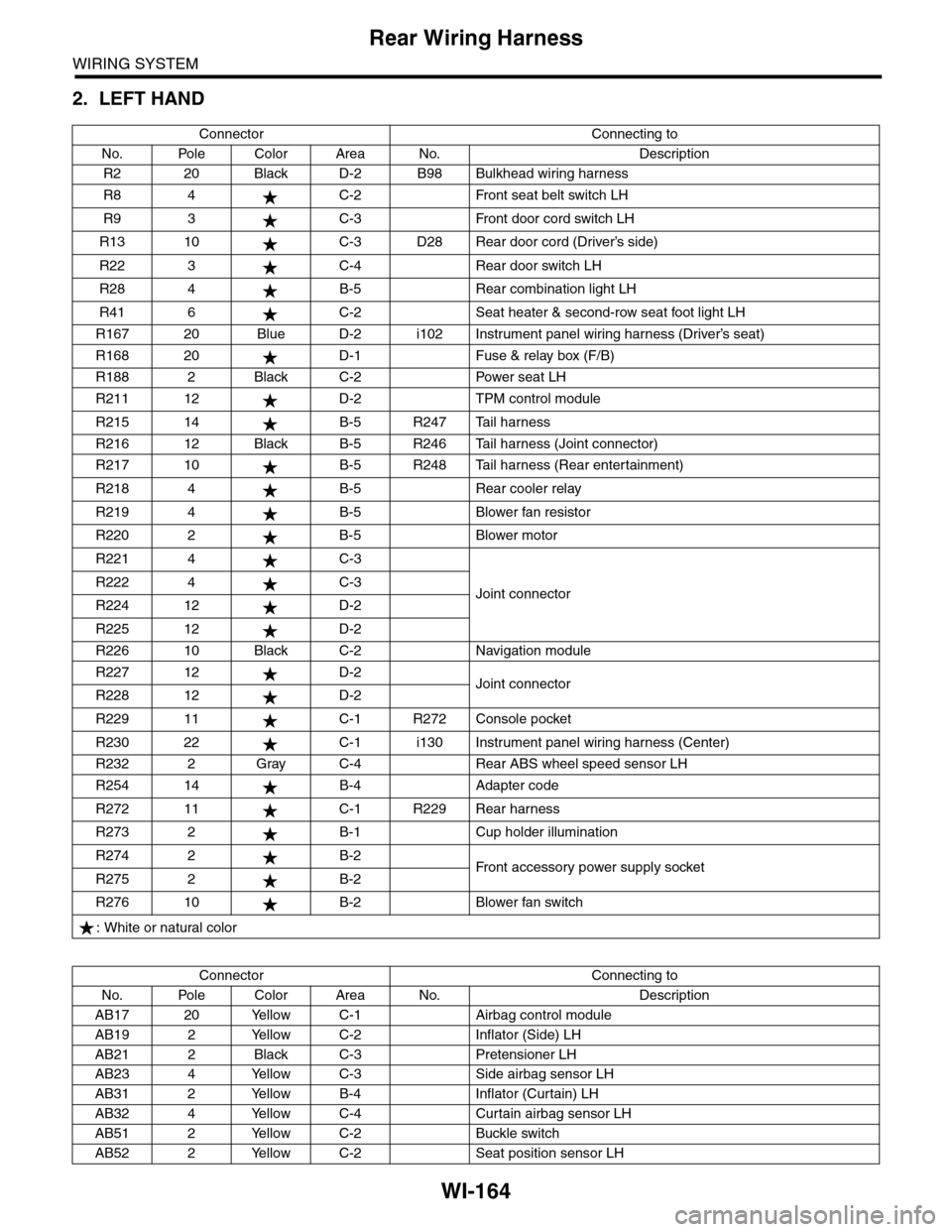
WI-164
Rear Wiring Harness
WIRING SYSTEM
2. LEFT HAND
Connector Connecting to
No. Pole Color Area No. Description
R2 20 Black D-2 B98 Bulkhead wiring harness
R8 4 C-2 Front seat belt switch LH
R9 3 C-3 Front door cord switch LH
R13 10 C-3 D28 Rear door cord (Driver’s side)
R22 3 C-4 Rear door switch LH
R28 4 B-5 Rear combination light LH
R41 6 C-2 Seat heater & second-row seat foot light LH
R167 20 Blue D-2 i102 Instrument panel wiring harness (Driver’s seat)
R168 20 D-1 Fuse & relay box (F/B)
R188 2 Black C-2 Power seat LH
R211 12 D-2 TPM control module
R215 14 B-5 R247 Tail harness
R216 12 Black B-5 R246 Tail harness (Joint connector)
R217 10 B-5 R248 Tail harness (Rear entertainment)
R218 4 B-5 Rear cooler relay
R219 4 B-5 Blower fan resistor
R220 2 B-5 Blower motor
R221 4 C-3
Joint connectorR222 4 C-3
R224 12 D-2
R225 12 D-2
R226 10 Black C-2 Navigation module
R227 12 D-2Joint connectorR228 12 D-2
R229 11 C-1 R272 Console pocket
R230 22 C-1 i130 Instrument panel wiring harness (Center)
R232 2 Gray C-4 Rear ABS wheel speed sensor LH
R254 14 B-4 Adapter code
R272 11 C-1 R229 Rear harness
R273 2 B-1 Cup holder illumination
R274 2 B-2Fr o nt a cc es so r y p ower s up pl y s ocke tR275 2 B-2
R276 10 B-2 Blower fan switch
: White or natural color
Connector Connecting to
No. Pole Color Area No. Description
AB17 20 Yellow C-1 Airbag control module
AB19 2 Yellow C-2 Inflator (Side) LH
AB21 2 Black C-3 Pretensioner LH
AB23 4 Yellow C-3 Side airbag sensor LH
AB31 2 Yellow B-4 Inflator (Curtain) LH
AB32 4 Yellow C-4 Curtain airbag sensor LH
AB51 2 Yellow C-2 Buckle switch
AB52 2 Yellow C-2 Seat position sensor LH