Page 1553 of 2453

EN(H6DO)(diag)-392
General Diagnostic Table
ENGINE (DIAGNOSTICS)
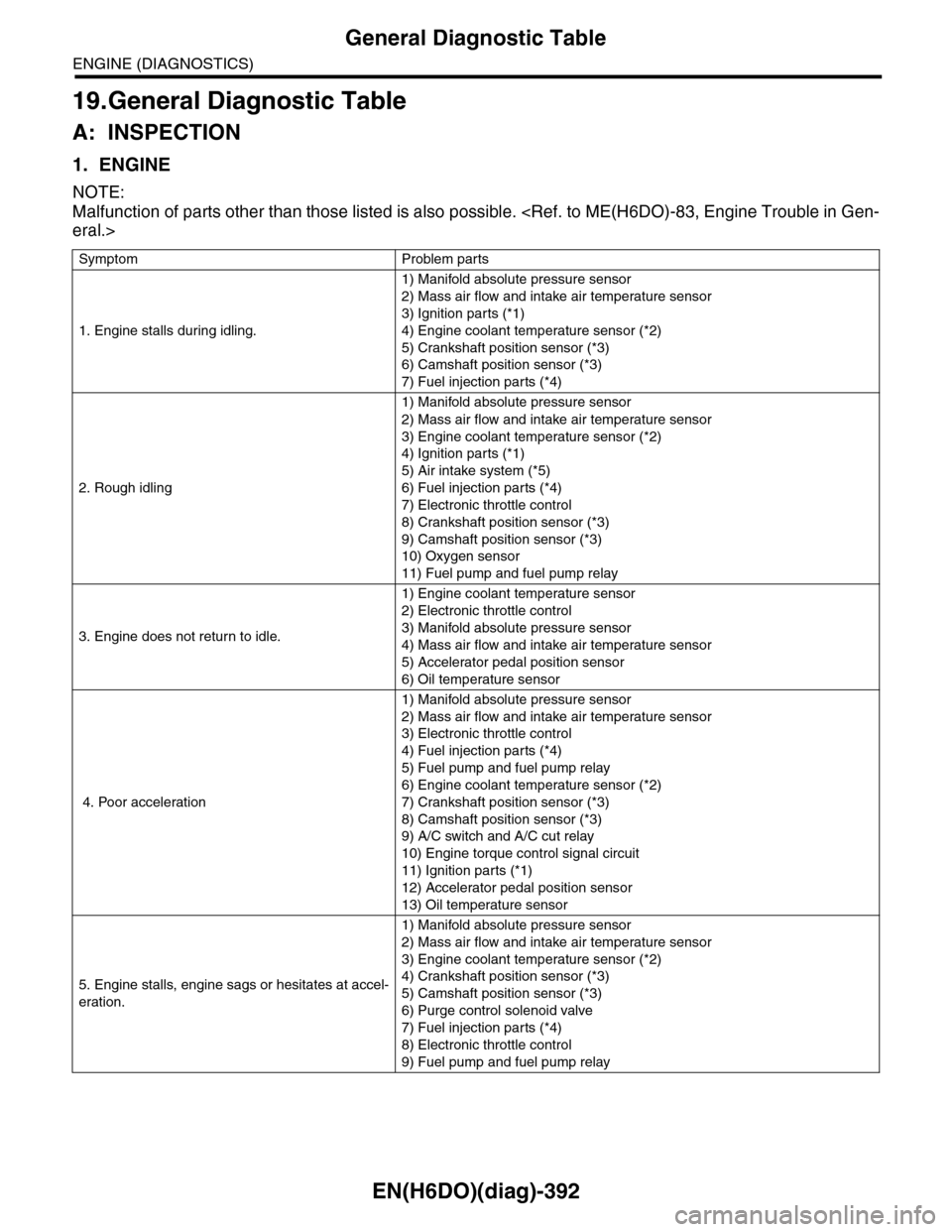
19.General Diagnostic Table
A: INSPECTION
1. ENGINE
NOTE:
Malfunction of parts other than those listed is also possible.
eral.>
Symptom Problem parts
1. Engine stalls during idling.
1) Manifold absolute pressure sensor
2) Mass air flow and intake air temperature sensor
3) Ignition parts (*1)
4) Engine coolant temperature sensor (*2)
5) Crankshaft position sensor (*3)
6) Camshaft position sensor (*3)
7) Fuel injection parts (*4)
2. Rough idling
1) Manifold absolute pressure sensor
2) Mass air flow and intake air temperature sensor
3) Engine coolant temperature sensor (*2)
4) Ignition parts (*1)
5) Air intake system (*5)
6) Fuel injection parts (*4)
7) Electronic throttle control
8) Crankshaft position sensor (*3)
9) Camshaft position sensor (*3)
10) Oxygen sensor
11) Fuel pump and fuel pump relay
3. Engine does not return to idle.
1) Engine coolant temperature sensor
2) Electronic throttle control
3) Manifold absolute pressure sensor
4) Mass air flow and intake air temperature sensor
5) Accelerator pedal position sensor
6) Oil temperature sensor
4. Poor acceleration
1) Manifold absolute pressure sensor
2) Mass air flow and intake air temperature sensor
3) Electronic throttle control
4) Fuel injection parts (*4)
5) Fuel pump and fuel pump relay
6) Engine coolant temperature sensor (*2)
7) Crankshaft position sensor (*3)
8) Camshaft position sensor (*3)
9) A/C switch and A/C cut relay
10) Engine torque control signal circuit
11) Ignition parts (*1)
12) Accelerator pedal position sensor
13) Oil temperature sensor
5. Engine stalls, engine sags or hesitates at accel-
eration.
1) Manifold absolute pressure sensor
2) Mass air flow and intake air temperature sensor
3) Engine coolant temperature sensor (*2)
4) Crankshaft position sensor (*3)
5) Camshaft position sensor (*3)
6) Purge control solenoid valve
7) Fuel injection parts (*4)
8) Electronic throttle control
9) Fuel pump and fuel pump relay
Page 1554 of 2453

EN(H6DO)(diag)-393
General Diagnostic Table
ENGINE (DIAGNOSTICS)
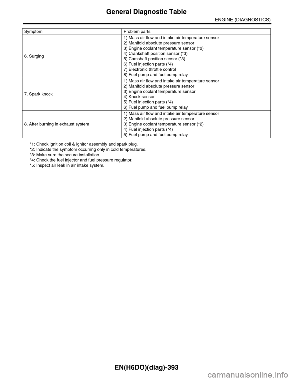
*1: Check ignition coil & ignitor assembly and spark plug.
*2: Indicate the symptom occurring only in cold temperatures.
*3: Make sure the secure installation.
*4: Check the fuel injector and fuel pressure regulator.
*5: Inspect air leak in air intake system.
6. Surging
1) Mass air flow and intake air temperature sensor
2) Manifold absolute pressure sensor
3) Engine coolant temperature sensor (*2)
4) Crankshaft position sensor (*3)
5) Camshaft position sensor (*3)
6) Fuel injection parts (*4)
7) Electronic throttle control
8) Fuel pump and fuel pump relay
7. Spark knock
1) Mass air flow and intake air temperature sensor
2) Manifold absolute pressure sensor
3) Engine coolant temperature sensor
4) Knock sensor
5) Fuel injection parts (*4)
6) Fuel pump and fuel pump relay
8. After burning in exhaust system
1) Mass air flow and intake air temperature sensor
2) Manifold absolute pressure sensor
3) Engine coolant temperature sensor (*2)
4) Fuel injection parts (*4)
5) Fuel pump and fuel pump relay
Symptom Problem parts
Page 1563 of 2453
FU(H6DO)-2
General Description
FUEL INJECTION (FUEL SYSTEMS)
1. General Description
A: SPECIFICATION
Fuel tankCapacity 64 2 (16.9 US gal, 14.1 Imp gal)
Location Rear floor bottom
Fuel pump
Ty p e I m p e l l e r
Shutoff discharge pressure550 — 850 kPa (5.61 — 8.67 kg/cm2, 79.8 — 123.3 psi)
Discharge rate155 2 (41 US gal, 34.1 Imp gal)/h or more
[12 V at 300 kPa (3.06 kg/cm2, 43.5 psi)]
Fuel filterIn-tank type
Page 1564 of 2453
FU(H6DO)-3
General Description
FUEL INJECTION (FUEL SYSTEMS)
B: COMPONENT
1. INTAKE MANIFOLD
FU-02706
T4
T5
T4
T4
T4
T5
(5)(6)
(2)
(12)
(2)
T2
T2
T2
T3
(10)
T3
(9)
(11)
T1
T2
T2
(14)(13)
(14)
(14)(13)(14)
T1
(4)
(3)
T2
T4
(7)
(8)
(1)
Page 1565 of 2453
FU(H6DO)-4
General Description
FUEL INJECTION (FUEL SYSTEMS)
2. FUEL INJECTOR
(1) Intake manifold (8) HoseTightening torque: N·m (kgf-m, ft-lb)
(2) O-ring (9) NippleT1: 1.5 (0.15, 1.1)
(3) Manifold absolute pressure sensor (10) PlugT2: 6.4 (0.65, 4.7)
(4) Filter (11) Fuel pipe protector LHT3: 17 (1.7, 12.5)
(5) Fuel pipe protector RH (12) Fuel pipe ASSYT4: 19 (1.9, 14)
(6) Purge control solenoid valve (13) HoseT5: 25 (2.5, 18)
(7) Hose (14) Clamp
(1) Fuel injector pipe LH (4) Injection rubberTightening torque: N·m (kgf-m, ft-lb)
(2) Insulator (5) O-ringT: 19 (1.9, 14)
(3) Fuel injector (6) Fuel injector pipe RH
FU-02561
(6)
T
T
(5)
(4)
(3)
(2)
(2)(3)(4)(5)
(1)
Page 1566 of 2453
FU(H6DO)-5
General Description
FUEL INJECTION (FUEL SYSTEMS)
3. AIR INTAKE SYSTEM
(1) O-ring Tightening torque: N·m (kgf-m, ft-lb)
(2) Throttle body T: 8 (0.8, 5.9)
FU-02109
(1)
(2)
T
Page 1567 of 2453
FU(H6DO)-6
General Description
FUEL INJECTION (FUEL SYSTEMS)
4. CRANKSHAFT POSITION, CAMSHAFT POSITION AND KNOCK SENSORS
(1) Crankshaft position sensor (6) Variable valve lift diagnosis oil
pressure switch RH
Tightening torque: N·m (kgf-m, ft-lb)
(2) Knock sensor RHT1: 6.4 (0.65, 4.7)
(3) Knock sensor LH (7) Variable valve lift diagnosis oil
pressure switch LH
T2: 17 (1.7, 12.5)
(4) Camshaft position sensor RHT3: 18 (1.8, 13.3)
(5) Camshaft position sensor LH (8) Oil temperature sensorT4: 25 (2.5, 18)
FU-02110
(6)
(4)
T2
T1
(3)
T4
(1)
(8)
T1
T3
(5)
T1
(2)
T4
(7)
T2
Page 1568 of 2453
FU(H6DO)-7
General Description
FUEL INJECTION (FUEL SYSTEMS)
5. FUEL TANK
T4
T1
T4
T3
T2
T3
T3
T4
T1
(15)
(14)
(14)
(11)
(10)
(5)
(6)
(4)
(3)
(20)
(21)
(22)
(2)
(8)
(9)
(7)
(16)
(17)
(18)
(12)
(13)
(19)
(1)
T2T3
(6)
FU-02677