Page 217 of 2453
ET-32
Steering Satellite Switch
ENTERTAINMENT
27.Steering Satellite Switch
A: REMOVAL
1) Disconnect the ground cable from battery.
2) Set the tire to the straight-ahead position.
3) Remove the airbag module.
MOVAL, Driver’s Airbag Module.>
WARNING:
If there are air bag modules mounted, always
refer to “Airbag System” when performing air-
bag module service.
TION, Driver’s Airbag Module.>
4) Remove the steering wheel.
MOVAL, Steering Wheel.>
5) Remove the cover from steering wheel.
6) Remove 2 satellite switch mounting screws each
from the left and right sides.
7) Remove the satellite switch.
B: INSTALLATION
Install in the reverse order of removal.
ET-00192
Page 282 of 2453

EI-40
Instrument Panel Assembly
EXTERIOR/INTERIOR TRIM
17.Instrument Panel Assembly
A: REMOVAL
CAUTION:
Take care of the following when removing the
instrument panel from the vehicle body.
•Refer to “CAUTION” of “General Description”
before starting the work.
TION, General Description.>
•Be sure to disconnect each harness connec-
tor. Applying excessive pulling force may dam-
age the harness.
•Be careful to the harness of airbag system.
Damage of the harness may cause the air bag
system malfunction.
•Take care not to damage the interior trims
when removing the instrument panel from the
vehicle body.
NOTE:
•Putting alignment marks to each connector as
necessary facilitates the reassembly work.
•When storing the removed instrument panel, be
sure to prepare a table or the like to put the instru-
ment panel on in order to prevent damage.
1. INSTRUMENT PANEL UPPER
1) Disconnect the ground cable from battery and
wait for at least 20 seconds before starting work.
2) Remove the console box.
MOVAL, Console Box.>
3) Remove the instrument panel lower cover.
to EI-36, REMOVAL, Instrument Panel Lower Cov-
er.>
4) Remove the glove box.
AL, Glove Box.>
5) Remove the center console.
MOVAL, Center Console.>
6) Remove the audio unit.
MOVAL, Audio.>
7) Remove the combination meter assembly.
to IDI-11, REMOVAL, Combination Meter.>
8) Remove the upper grille.
PER GRILL, REMOVAL, Air Vent Grille.>
9) Remove the multi function display or navigation
monitor, and warning box.
MOVAL, Navigation Display.>
10) Remove the front pillar upper trim.
43, REMOVAL, Side Trim.>
11) Remove the mounting bolts of the passenger’s
side air bag module.
12) Remove the following screws.
•In combination meter house
•At the sides (left and right) of instrument panel
•Instrument panel center
EI-01327
EI-01328
EI-01330
EI-01329
Page 426 of 2453

IM (diag)-10
Diagnostics Chart for Security Indicator Light
IMMOBILIZER (DIAGNOSTICS)
8. Diagnostics Chart for Security Indicator Light
A: INSPECTION
1. CHECK SECURITY INDICATOR LIGHT CIRCUIT
WIRING DIAGRAM:
IM-00141
MAIN SBF
SBF-3
BATTERY
WARNING BOX
BODY INTEGRATED UNIT
i116
F/B NO.7
F/B NO.12
IGNITIONSWITCH
A33C2B7C9C8
2
1
E
A1
M/B NO.8
SBF-8
B22
i84A:
B280B:
B281C:
567821943102422 23 25111213141526 27281617181920 21
B281i84
1234567891011121314151617181920212223242526272829303132333435
5467821931022 231112131415242526 2716171828 29192021 30
B280A:C:B:
5i124
i102
i97
i98
SECURITYINDICATORLIGHT
JOINT CONNECTOR
i116
12345678910i98
i97
12345678910111213141516171819202122
: TERMINAL NO. OPTIONAL ARRANGEMENT AMONG 16, 17 AND 18
1*
1*
1*
Step Check Yes No
1CHECK SECURITY INDICATOR LIGHT.
1) Turn the ignition switch to OFF.
2) Disconnect the harness connector from
body integrated unit.
3) Connect the resistor (100 Ω) between body
integrated unit harness connector terminal
(i84) No. 33 and chassis ground.
Does the security indicator
light illuminate?
Go to step 2.Go to step 5.
Page 427 of 2453

IM (diag)-11
Diagnostics Chart for Security Indicator Light
IMMOBILIZER (DIAGNOSTICS)
2CHECK BODY INTEGRATED UNIT GROUND
CIRCUIT.
Measure the resistance between body inte-
grated unit harness connector terminal and
chassis ground.
Connector & terminal
(B280) No. 22 — Chassis ground:
(B281) No. 8, No. 9 — Chassis ground:
Is the resistance less than 10
Ω?
Go to step 3.Repair the open
circuit of body inte-
grated unit ground
circuit.
3CHECK BODY INTEGRATED UNIT IGNITION
CIRCUIT.
1) Turn the ignition switch to ON.(Engine OFF)
2) Measure the voltage between body inte-
grated unit harness connector terminal and
chassis ground.
Connector & terminal
(i84) No. 1 (+) — Chassis ground (–):
Is the voltage more than 10 V? Go to step 4.Check the harness
for open or shor t
circuit between
body integrated
unit and ignition
switch.
4CHECK BODY INTEGRATED UNIT POWER
SUPPLY CIRCUIT.
1) Turn the ignition switch to OFF.
2) Measure the voltage between body inte-
grated unit harness connector terminal and
chassis ground.
Connector & terminal
(B280) No. 7 (+) — Chassis ground (–):
(B281) No. 2 (+) — Chassis ground (–):
Is the voltage more than 10 V? Replace the body
integrated unit
Body Integrated
Unit.> and replace
all the ignition keys
(including tran-
sponder). Execute
the registration
procedure next.
Refer to the “REG-
ISTRATION MAN-
UAL FO R
IMMOBILIZER”.
Check the harness
for open or shor t
circuit between
body integrated
unit and fuse.
5INSPECT WARNING BOX CIRCUIT.
1) Remove the warning box.
REMOVAL, Warning Box.>
2) Measure the voltage between the warning
box harness connector terminal and chassis
ground.
Connector & terminal
(i116) No. 1 (+) — Chassis ground (–):
Is the voltage more than 10 V? Go to step 6.Check the harness
for open or shor t
circuit between
warning box and
fuse.
6INSPECT WARNING BOX CIRCUIT.
Measure the resistance between body inte-
grated unit harness connector terminal and
warning box harness connector terminal.
Connector & terminal
(i84) No. 33 — (i116) No. 2:
Is the resistance less than 10
Ω?
LED bulb malfunc-
tion. Replace the
warning box.
to IDI-17,
REMOVAL, Warn-
ing Box.>
Repair the har-
ness or connector.
Step Check Yes No
Page 428 of 2453
IM (diag)-12
Diagnostics Chart for Security Indicator Light
IMMOBILIZER (DIAGNOSTICS)
2. CHECK KEY SWITCH CIRCUIT
WIRING DIAGRAM:
IM-00078
B350
KEY WARNINGSWITCH
B281
BODY INTEGRATEDMODULE
BATTERYM/B No.14
C7
3
4
C:
567821943102422 23 25111213141526 27281617181920 21
B281C:B350
1234
Page 429 of 2453

IM (diag)-13
Diagnostics Chart for Security Indicator Light
IMMOBILIZER (DIAGNOSTICS)
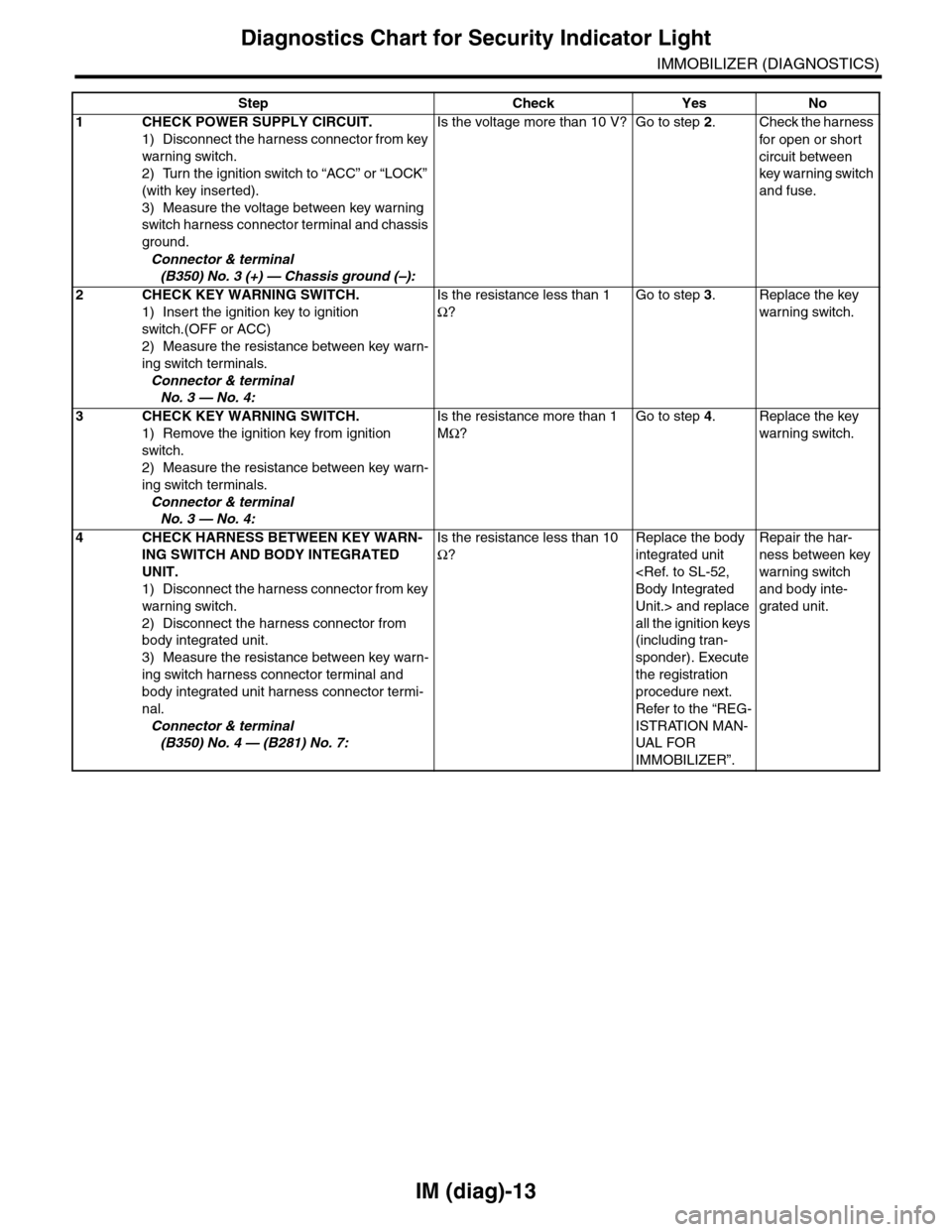
Step Check Yes No
1CHECK POWER SUPPLY CIRCUIT.
1) Disconnect the harness connector from key
warning switch.
2) Turn the ignition switch to “ACC” or “LOCK”
(with key inserted).
3) Measure the voltage between key warning
switch harness connector terminal and chassis
ground.
Connector & terminal
(B350) No. 3 (+) — Chassis ground (–):
Is the voltage more than 10 V? Go to step 2.Check the harness
for open or shor t
circuit between
key warning switch
and fuse.
2 CHECK KEY WARNING SWITCH.
1) Insert the ignition key to ignition
switch.(OFF or ACC)
2) Measure the resistance between key warn-
ing switch terminals.
Connector & terminal
No. 3 — No. 4:
Is the resistance less than 1
Ω?
Go to step 3.Replace the key
warning switch.
3 CHECK KEY WARNING SWITCH.
1) Remove the ignition key from ignition
switch.
2) Measure the resistance between key warn-
ing switch terminals.
Connector & terminal
No. 3 — No. 4:
Is the resistance more than 1
MΩ?
Go to step 4.Replace the key
warning switch.
4CHECK HARNESS BETWEEN KEY WARN-
ING SWITCH AND BODY INTEGRATED
UNIT.
1) Disconnect the harness connector from key
warning switch.
2) Disconnect the harness connector from
body integrated unit.
3) Measure the resistance between key warn-
ing switch harness connector terminal and
body integrated unit harness connector termi-
nal.
Connector & terminal
(B350) No. 4 — (B281) No. 7:
Is the resistance less than 10
Ω?
Replace the body
integrated unit
Body Integrated
Unit.> and replace
all the ignition keys
(including tran-
sponder). Execute
the registration
procedure next.
Refer to the “REG-
ISTRATION MAN-
UAL FO R
IMMOBILIZER”.
Repair the har-
ness between key
warning switch
and body inte-
grated unit.
Page 441 of 2453

IDI-2
General Description
INSTRUMENTATION/DRIVER INFO
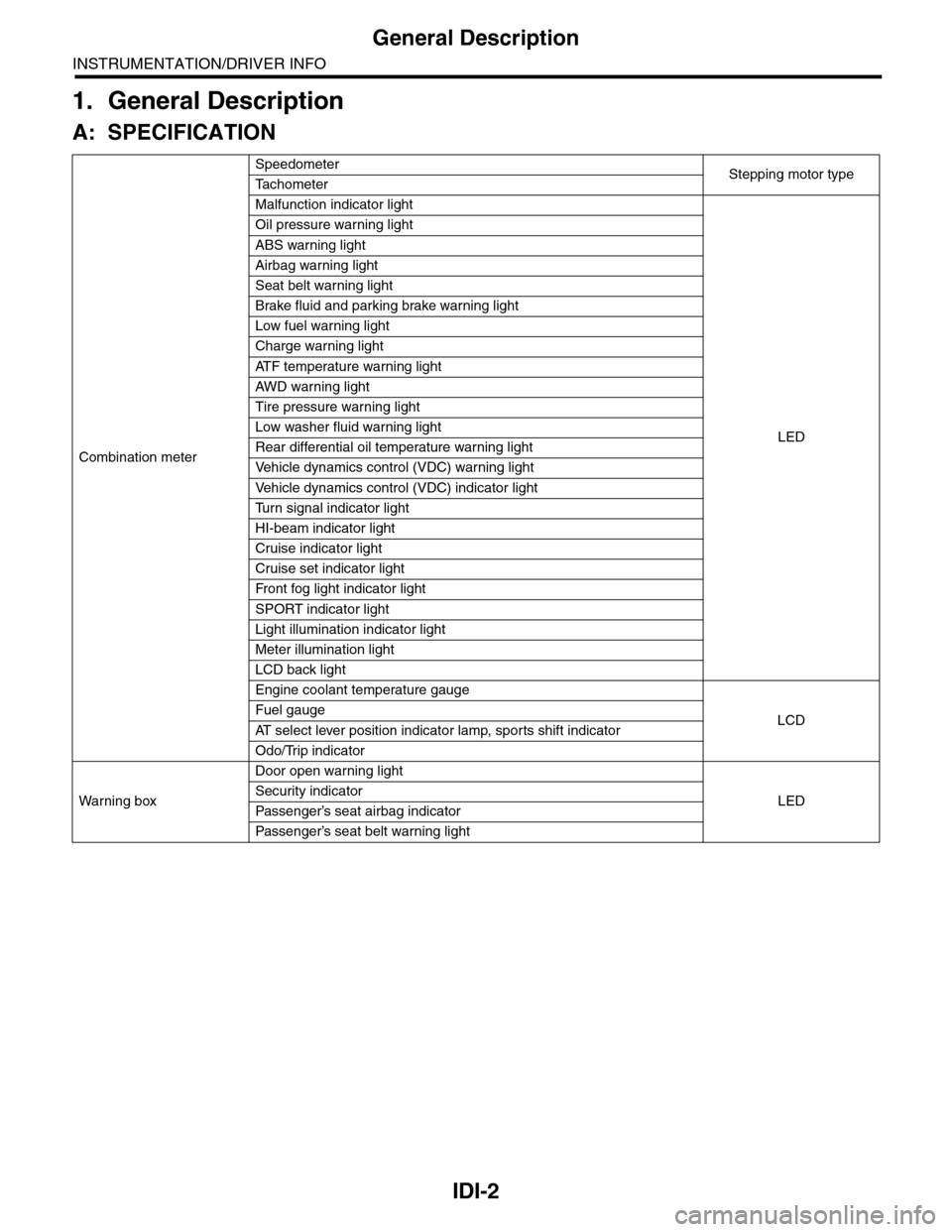
1. General Description
A: SPECIFICATION
Combination meter
SpeedometerStepping motor typeTa c h o m e t e r
Malfunction indicator light
LED
Oil pressure warning light
ABS warning light
Airbag warning light
Seat belt warning light
Brake fluid and parking brake warning light
Low fuel warning light
Charge warning light
AT F t e m p e r a t u r e w a r n i n g l i g h t
AW D war n in g l i gh t
Tire pressure warning light
Low washer fluid warning light
Rear differential oil temperature warning light
Ve h i c l e d y n a m i c s c o n t r o l ( V D C ) w a r n i n g l i g h t
Ve h i c l e d y n a m i c s c o n t r o l ( V D C ) i n d i c a t o r l i g h t
Tu r n s i g n a l i n d i c a t o r l i g h t
HI-beam indicator light
Cruise indicator light
Cruise set indicator light
Fr o nt fog li g ht i nd i ca to r li g ht
SPORT indicator light
Light illumination indicator light
Meter illumination light
LCD back light
Engine coolant temperature gauge
LCDFuel gauge
AT s e l e c t l e v e r p o s i t i o n i n d i c a t o r l a m p , s p o r t s s h i f t i n d i c a t o r
Odo/Trip indicator
Wa r ni n g b ox
Door open warning light
LEDSecurity indicator
Passenger’s seat airbag indicator
Passenger’s seat belt war ning light
Page 443 of 2453

IDI-4
Combination Meter System
INSTRUMENTATION/DRIVER INFO
2. Combination Meter System
A: WIRING DIAGRAM
1. COMBINATION METER
Meter System.>
B: INSPECTION
1. SELF-DIAGNOSIS
The self-diagnosis (checking of each meter, warn-
ing light, indicator, illumination, LCD, buzzer
sound) of combination meter can be performed in
the following procedure.
1) Turn the ignition switch to ON while turning the
small light to OFF.
2) Step 1) Turn the small light switch to ON within 3
seconds after step 1), then press the odo/tripmeter
knob three times.
3) Turn the small light switch to OFF, and press the
odo/trip knob three times.
4) Turn the small light switch to ON, and press the
odo/trip knob three times.
NOTE:
•Perform the steps described in 2) and 4) within
10 seconds after the ignition switch is turned to ON.
•When pressing the odo/trip meter knob four
times, the display changes to DTC display mode
(ECM, TCM).
MODE, INSPECTION, Combination Meter Sys-
tem.>When the self-diagnosis function operates,
the warning light, indicator, and LCD display are
checked, then every press of the odo/trip meter
knob will initiate the operation checks in the order
of meter, illumination and buzzer.
LIST OF SELF-DIAGNOSIS MODE OPERATION,
INSPECTION, Combination Meter System.> Turn
the ignition switch to OFF to cancel the self-diagno-
sis function.
•When the engine starts during diagnosis, the
self-diagnosis function is not cancelled, however,
once the vehicle starts driving, the self-diagnosis
function is cancelled automatically for safety.