2009 SUBARU TRIBECA generator
[x] Cancel search: generatorPage 189 of 2453

ET-3
Audio System
ENTERTAINMENT
2. Audio System
A: WIRING DIAGRAM
B: INSPECTION
Symptom Repair order
No power coming in. (No display and no sound from speakers) 1. Check the fuse and power supply for audio.
2. Check the audio ground.
3. Remove the audio and repair them.
A specific speaker does not operate. 1. Check the speaker.
2. Check the output circuit between audio and speaker.
Audio generates noise with engine is r unning. 1. C heck the audio ground.
2. Check the generator.
3. Check the ignition coil.
4. Remove the audio and repair them.
Vo l u m e i s l o w i n A M a n d F M m o d e s o r i n t e r f e r e n c e n o i s e
occurs.
1. Check the antenna.
2. Check the antenna amplifier.
3. Check the noise suppressor.
4. Check the audio ground.
5. Remove the audio and repair them.
Page 359 of 2453

AC-33
Compressor
HVAC SYSTEM (HEATER, VENTILATOR AND A/C)
14.Compressor
A: INSPECTION
1. MAGNETIC CLUTCH CLEARANCE
Check the clearance of the entire circumference
around the drive plate and pulley.
Standard:
0.45±0.15 mm (0.0177±0.0059 in)
2. MAGNETIC CLUTCH OPERATION
1) Disconnect the compressor connector.
2) Connect the positive (+) lead from the battery to
the compressor connector terminal, and the nega-
tive (–) lead to the compressor body.
3) Check the magnet clutch engagement.
If there is a problem, replace the compressor.
B: REMOVAL
1) Perform the compressor oil return operation.
2) Turn the A/C switch to OFF and stop the engine.
3) Using the refrigerant recovery system, dis-
charge refrigerant.
4) Disconnect the ground cable from battery.
5) Remove the V-belts.
6) Remove the generator.
7) Remove the bolt and remove the low-pressure
hose and high-pressure hose.
8) Disconnect the compressor harness from the
body harness.
9) Remove the bolts and remove the compressor
bracket.
10) Remove the bolts, then remove the bracket
from the compressor.
C: INSTALLATION
1) Install in the reverse order of removal.
2) Replace the O-rings on low-/high-pressure hos-
es with new parts, then apply compressor oil.
3) After replacing the compressor, adjust the
amount of compressor oil.
4) Charge refrigerant.
Tightening torque:
Refer to “COMPONENT” of “General Descrip-
tion”.
AC-01287
AC-01381
AC-01289
AC-01290
Page 380 of 2453

AC(diag)-3
General Description
HVAC SYSTEM (AUTO A/C) (DIAGNOSTICS)
2. General Description
A: CAUTION
1) Never connect the battery in reverse polarity.
•Auto A/C control module may be destroyed in-
stantly.
2) Do not disconnect the battery terminals while the
engine is running.
•A large counter electromotive force will be gener-
ated in the generator, and this voltage may damage
electronic parts such as auto A/C control module
etc.
3) Before disconnecting the connectors of each
sensor and the auto A/C control module, be sure to
turn the ignition switch to OFF.
•Auto A/C control module may be damaged.
4) Every A/C-related part is a precision part. Do not
drop them.
5) Airbag system wiring harness is routed near the
A/C control panel and junction box.
CAUTION:
•For airbag system, yellow-colored wiring har-
ness and connectors are all used. Do not use
the electrical test equipment on these circuits.
•Be careful not to damage the airbag system
wiring harness when servicing the A/C control
panel and junction box.
B: INSPECTION
Before performing the diagnosis, check the follow-
ing items which might affect A/C system problems.
1. BATTERY
1) Measure the battery voltage and specific gravity
of electrolyte.
Standard voltage: 12 V
Specific gravity: 1.260 or more
2) Check the condition of the fuses for A/C system
power supply and other fuses.
3) Check the condition of harness and harness
connector connections.
2. ASPIRATOR HOSE
1) Turn the ignition switch to ON, and press the A/
C switch.
2) Turn the temperature control dial to maximum
hot position.
3) Turn the air flow control dial to “DEF” position.
4) Turn the fan speed control dial to 4th position.
5) Put a strip of paper close to the front side of in-
vehicle sensor suction port (A) located in the driv-
er’s side console side panel, and check that air is
being sucked into the port by seeing the paper
moving towards the port.
NOTE:
Be careful not to let the paper get sucked into the
port.
6) If the paper does not move at all, remove the
driver’s side console side panel
connection of the aspirator hose, in-vehicle sensor
and heater unit, and repair them if necessary.
3. A/C LINE
Check the connection for A/C line (A) and lower
side high-pressure pipe.
AC-01323
AC-01324
(A)
Page 572 of 2453
OD(diag)-4
General Description
OCCUPANT DETECTION SYSTEM (DIAGNOSTICS)
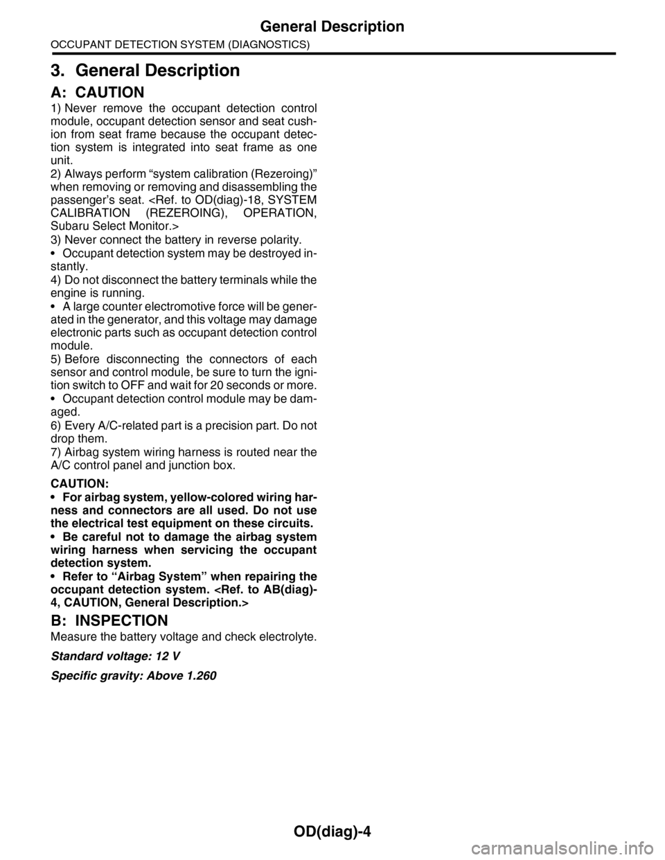
3. General Description
A: CAUTION
1) Never remove the occupant detection control
module, occupant detection sensor and seat cush-
ion from seat frame because the occupant detec-
tion system is integrated into seat frame as one
unit.
2) Always perform “system calibration (Rezeroing)”
when removing or removing and disassembling the
passenger’s seat.
Subaru Select Monitor.>
3) Never connect the battery in reverse polarity.
•Occupant detection system may be destroyed in-
stantly.
4) Do not disconnect the battery terminals while the
engine is running.
•A large counter electromotive force will be gener-
ated in the generator, and this voltage may damage
electronic parts such as occupant detection control
module.
5) Before disconnecting the connectors of each
sensor and control module, be sure to turn the igni-
tion switch to OFF and wait for 20 seconds or more.
•Occupant detection control module may be dam-
aged.
6) Every A/C-related part is a precision part. Do not
drop them.
7) Airbag system wiring harness is routed near the
A/C control panel and junction box.
CAUTION:
•For airbag system, yellow-colored wiring har-
ness and connectors are all used. Do not use
the electrical test equipment on these circuits.
•Be careful not to damage the airbag system
wiring harness when servicing the occupant
detection system.
•Refer to “Airbag System” when repairing the
occupant detection system.
B: INSPECTION
Measure the battery voltage and check electrolyte.
Standard voltage: 12 V
Specific gravity: Above 1.260
Page 1039 of 2453
VDC(diag)-47
Diagnostic Procedure with Diagnostic Trouble Code (DTC)
VEHICLE DYNAMICS CONTROL (VDC) (DIAGNOSTICS)
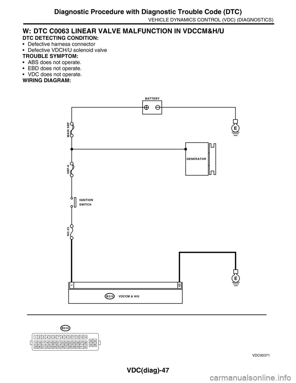
W: DTC C0063 LINEAR VALVE MALFUNCTION IN VDCCM&H/U
DTC DETECTING CONDITION:
•Defective harness connector
•Defective VDCH/U solenoid valve
TROUBLE SYMPTOM:
•ABS does not operate.
•EBD does not operate.
•VDC does not operate.
WIRING DIAGRAM:
MAIN SBF
SBF-6
NO.33
B310
E
E
431
VDCCM & H/U
BATTERY
GENERATOR
IGNITIONSWITCH
VDC00371
B310
1234
1516171819202122232425262728293031323334353637383940414245464344568910 11 12 13 147
Page 1040 of 2453
VDC(diag)-48
Diagnostic Procedure with Diagnostic Trouble Code (DTC)
VEHICLE DYNAMICS CONTROL (VDC) (DIAGNOSTICS)
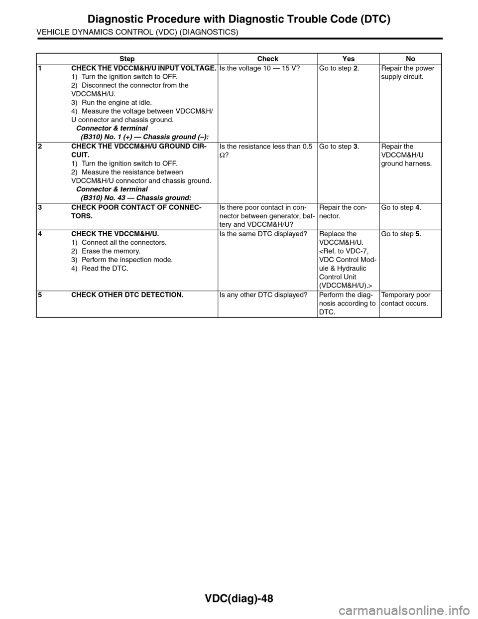
Step Check Yes No
1CHECK THE VDCCM&H/U INPUT VOLTAGE.
1) Turn the ignition switch to OFF.
2) Disconnect the connector from the
VDCCM&H/U.
3) Run the engine at idle.
4) Measure the voltage between VDCCM&H/
U connector and chassis ground.
Connector & terminal
(B310) No. 1 (+) — Chassis ground (–):
Is the voltage 10 — 15 V? Go to step 2.Repair the power
supply circuit.
2CHECK THE VDCCM&H/U GROUND CIR-
CUIT.
1) Turn the ignition switch to OFF.
2) Measure the resistance between
VDCCM&H/U connector and chassis ground.
Connector & terminal
(B310) No. 43 — Chassis ground:
Is the resistance less than 0.5
Ω?
Go to step 3.Repair the
VDCCM&H/U
ground harness.
3CHECK POOR CONTACT OF CONNEC-
TORS.
Is there poor contact in con-
nector between generator, bat-
tery and VDCCM&H/U?
Repair the con-
nector.
Go to step 4.
4CHECK THE VDCCM&H/U.
1) Connect all the connectors.
2) Erase the memory.
3) Perform the inspection mode.
4) Read the DTC.
Is the same DTC displayed? Replace the
VDCCM&H/U.
ule & Hydraulic
Control Unit
(VDCCM&H/U).>
Go to step 5.
5CHECK OTHER DTC DETECTION.Is any other DTC displayed? Perform the diag-
nosis according to
DTC.
Te m p o r a r y p o o r
contact occurs.
Page 1042 of 2453
VDC(diag)-50
Diagnostic Procedure with Diagnostic Trouble Code (DTC)
VEHICLE DYNAMICS CONTROL (VDC) (DIAGNOSTICS)
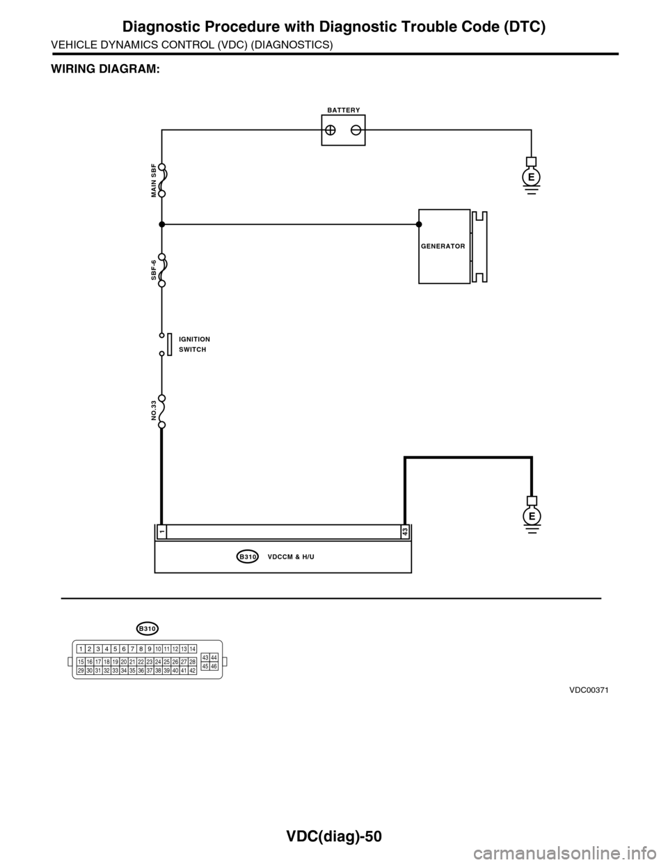
WIRING DIAGRAM:
MAIN SBF
SBF-6
NO.33
B310
E
E
431
VDCCM & H/U
BATTERY
GENERATOR
IGNITIONSWITCH
VDC00371
B310
1234
1516171819202122232425262728293031323334353637383940414245464344568910 11 12 13 147
Page 1043 of 2453
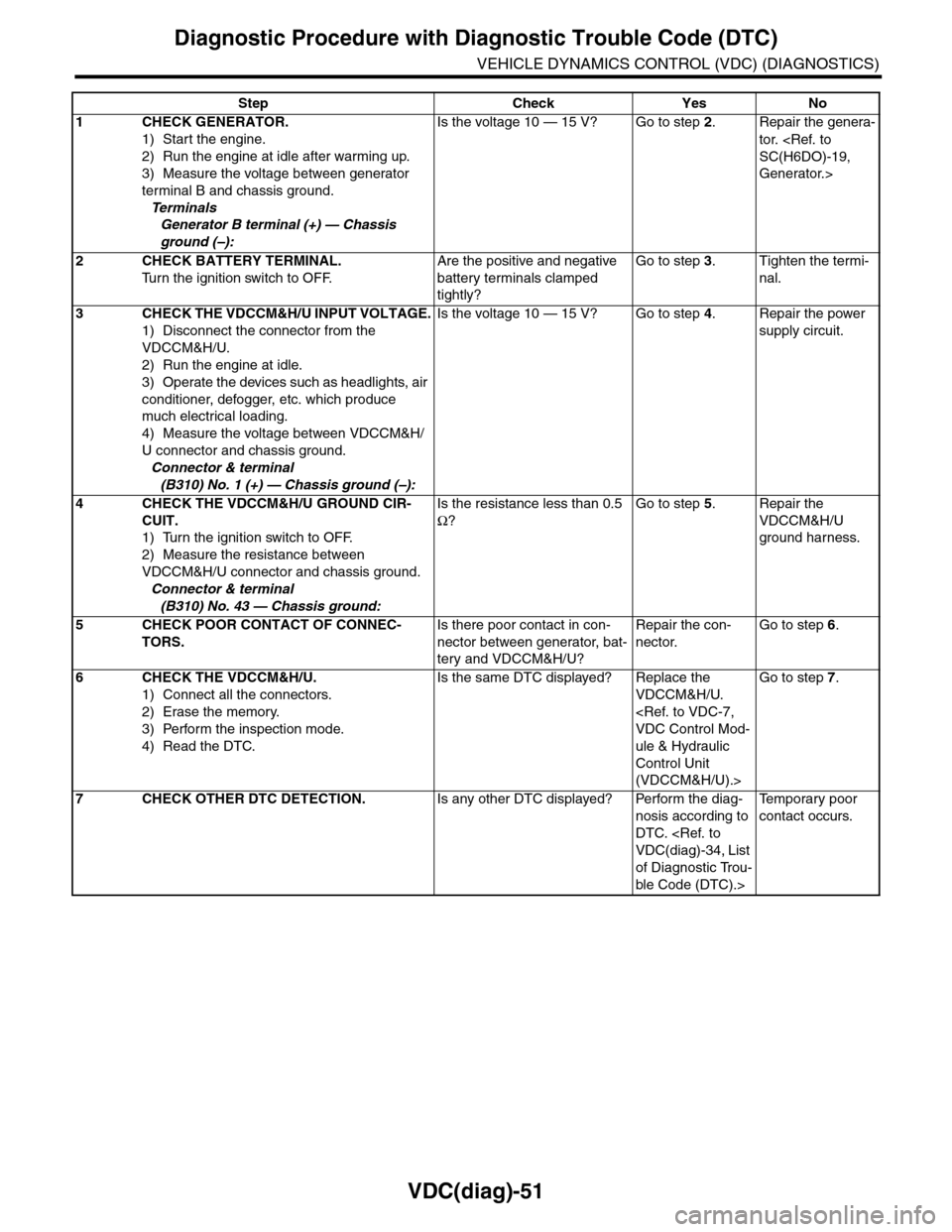
VDC(diag)-51
Diagnostic Procedure with Diagnostic Trouble Code (DTC)
VEHICLE DYNAMICS CONTROL (VDC) (DIAGNOSTICS)
Step Check Yes No
1CHECK GENERATOR.
1) Start the engine.
2) Run the engine at idle after warming up.
3) Measure the voltage between generator
terminal B and chassis ground.
Te r m i n a l s
Generator B terminal (+) — Chassis
ground (–):
Is the voltage 10 — 15 V? Go to step 2.Repair the genera-
tor.
Generator.>
2CHECK BATTERY TERMINAL.
Tu r n t h e i g n i t i o n s w i t c h t o O F F.
Are the positive and negative
battery terminals clamped
tightly?
Go to step 3.Tighten the termi-
nal.
3CHECK THE VDCCM&H/U INPUT VOLTAGE.
1) Disconnect the connector from the
VDCCM&H/U.
2) Run the engine at idle.
3) Operate the devices such as headlights, air
conditioner, defogger, etc. which produce
much electrical loading.
4) Measure the voltage between VDCCM&H/
U connector and chassis ground.
Connector & terminal
(B310) No. 1 (+) — Chassis ground (–):
Is the voltage 10 — 15 V? Go to step 4.Repair the power
supply circuit.
4CHECK THE VDCCM&H/U GROUND CIR-
CUIT.
1) Turn the ignition switch to OFF.
2) Measure the resistance between
VDCCM&H/U connector and chassis ground.
Connector & terminal
(B310) No. 43 — Chassis ground:
Is the resistance less than 0.5
Ω?
Go to step 5.Repair the
VDCCM&H/U
ground harness.
5CHECK POOR CONTACT OF CONNEC-
TORS.
Is there poor contact in con-
nector between generator, bat-
tery and VDCCM&H/U?
Repair the con-
nector.
Go to step 6.
6CHECK THE VDCCM&H/U.
1) Connect all the connectors.
2) Erase the memory.
3) Perform the inspection mode.
4) Read the DTC.
Is the same DTC displayed? Replace the
VDCCM&H/U.
ule & Hydraulic
Control Unit
(VDCCM&H/U).>
Go to step 7.
7CHECK OTHER DTC DETECTION.Is any other DTC displayed? Perform the diag-
nosis according to
DTC.
of Diagnostic Trou-
ble Code (DTC).>
Te m p o r a r y p o o r
contact occurs.