Page 1982 of 2453
SC(H6DO)-24
Generator
STARTING/CHARGING SYSTEMS
4. BRUSH
1) Measure the length of each brush. If wear ex-
ceeds the service limit, replace the brush. Each
brush has the service limit mark (A) on it.
Brush length:
Service limit (1)
5.0 mm (0.197 in)
Standard (2)
18.5 mm (0.728 in)
2) Checking brush spring for proper pressure
Using a spring pressure indicator, push the brush
into the brush holder until its tip protrudes 2 mm
(0.08 in). Then measure the pressure of brush
spring. If the pressure is less than 2.2 N (224 g, 7
91 oz), replace the brush spring with a new one.
The new spring must have a pressure of 4.8 to 6.0
N (489 to 612 g, 17.26 to 21.58 oz).
5. BEARING (FRONT SIDE)
Check the front ball bearing. If the resistance is felt
while rotating, or abnormal noise is heard, replace
the ball bearing
SC-00162
(A)
(1)
(2)
SC-00093
Page 1984 of 2453

SC(H6DO)-26
Battery
STARTING/CHARGING SYSTEMS
3. SPECIFIC GRAVITY OF ELECTROLYTE
1) Measure specific gravity of electrolyte using a
hydrometer and a thermometer.
Specific gravity varies with temperature of electro-
lyte so that it must be corrected at 20°C (68°F) us-
ing the following equation:
S20 = St + 0.0007 × (t – 20)
S20: Specific gravity corrected at electrolyte
temperature of 20°C (68°F)
St: Measured specific gravity
t: Measured temperature (°C)
Determine whether or not battery must be
charged, according to corrected specific
gravity.
Standard specific gravity: 1.220 — 1.290
[20°C (68°F)]
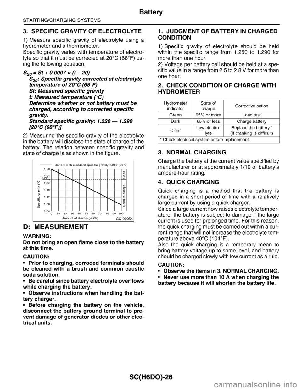
2) Measuring the specific gravity of the electrolyte
in the battery will disclose the state of charge of the
battery. The relation between specific gravity and
state of charge is as shown in the figure.
D: MEASUREMENT
WARNING:
Do not bring an open flame close to the battery
at this time.
CAUTION:
•Prior to charging, corroded terminals should
be cleaned with a brush and common caustic
soda solution.
•Be careful since battery electrolyte overflows
while charging the battery.
•Observe instructions when handling the bat-
tery charger.
•Before charging the battery on the vehicle,
disconnect the battery ground terminal to pre-
vent damage of generator diodes or other elec-
trical units.
1. JUDGMENT OF BATTERY IN CHARGED
CONDITION
1) Specific gravity of electrolyte should be held
within the specific range from 1.250 to 1.290 for
more than one hour.
2) Voltage per battery cell should be held at a spe-
cific value in a range from 2.5 to 2.8 V for more than
one hour.
2. CHECK CONDITION OF CHARGE WITH
HYDROMETER
3. NORMAL CHARGING
Charge the battery at the current value specified by
manufacturer or at approximately 1/10 of battery's
ampere-hour rating.
4. QUICK CHARGING
Quick charging is a method that the battery is
charged in a short period of time with a relatively
large current by using a quick charger.
Since a large current flow raises electrolyte temper-
ature, the battery is subject to damage if the large
current is used for prolonged time. For this reason,
the quick charging must be carried out within a cur-
rent range that will not increase the electrolyte tem-
perature above 40°C (104°F).
Also the quick charging is a temporary mean to
bring battery voltage up to some level, and battery
should be charged slowly with low current as a rule.
CAUTION:
•Observe the items in 3. NORMAL CHARGING.
•Never use more than 10 A when charging the
battery because it will shorten the battery life.
SC-00054
010 20 30 40 50 60 70 80 90 100
1.12
1.20
1.16
1.24
1.28
1.22
1.08
1.04
Amount of discharge (%)
Specific gravity ( C)
Battery with standard specific gravity 1,280 (20 C)
Good
Need to charge
Hydrometer
indicator
State of
chargeCorrective action
Green 65% or more Load test
Dark 65% or less Charge battery
ClearLow electro-
lyte
Replace the battery.*
(If cranking is difficult)
* Check electrical system before replacement.
Page 1993 of 2453
PM-10
V-belt
PERIODIC MAINTENANCE SERVICES
6. V-belt
A: INSPECTION
1) Replace the belts if cracks, fraying or wear are
found.
2) Make sure that the V-belt automatic belt tension
indicator (A) is within the range of its use limit (D).
B: REPLACEMENT
1) Remove the cover.
2) Fit the tool to the belt tensioner mounting bolt.
3) Turn the tool in the direction of the arrow, and
loosen the V-belt to remove it.
4) Install in the reverse order of removal.
(A) Indicator
(B) Generator
(C) Power steering oil pump
(D) Service limit
(B)
(A)
(D)
(C)
ME-00475
(1) Power steering oil pump
(2) Belt tension adjuster
(3) Crank pulley
(4) A/C compressor
(5) Belt idler
(6) Generator
PM-00301
(1)(6)
(4)
(5)(2)
(3)ME-00474
Page 2300 of 2453
WI-16
Power Supply Circuit
WIRING SYSTEM
WI-08026
P-SUP-02P-SUP-02
WR
BR
WB21BR3
B14B7C10
GENERATOR
MAIN FUSE BOX(M/B)
BATTERY
MB-2
F26
MB-29MB-1MB-9MB-8MB-6
A7A9
A16
P-SUP-05B
P-SUP-05A
P-SUP-03C
NO. 4 25A
MAINSBF 120A
P-SUP-04I
P-SUP-04H
P-SUP-03D
NO. 2 25ANO. 8 20ANO. 3 25ANO. 5 20ANO. 1 30ANO. 16 7.5A
NO. 10 25A
SBF-1 50ASBF-8 50ASBF-6 50ASBF-3 50ASBF-2 50A
E5E6
RL
G7H8
GOrGB
WH4B19
ALT-1
B433B145G:
12
F26
123
B186H:(BROWN)B144D:(BLUE)F35C:
A:
12345678123456789101112
F37
F:
P-SUP-05G
P-SUP-05F
P-SUP-04E
MAIN FANRELAY 1
REAR DEFOGGER
RELAY
WW
F37A:
B143B:
F35C:
B144D:
F36E:
B433F:
B145G:
B186H:
LR
D9
G
D3
W
D2
R
D6E3D1
RY
D5
WR
D7B11
L
D8
MB-5
1234567
157628349
1234 5678910 11 12 13 14 15 16 17 18 19 20
B:B143
1234 5678910 11 12 13 14 15 16 17 18 19 20
CURRENT FROM IGNITIONSWITCH "IG" TERMINAL
OTHER CURRENT
BATTERY CURRENT
CURRENT FROM IGNITIONSWITCH "ACC" TERMINAL
GRLWLg
F36E:
(BROWN)
Page 2316 of 2453

WI-32
Engine Electrical System
WIRING SYSTEM
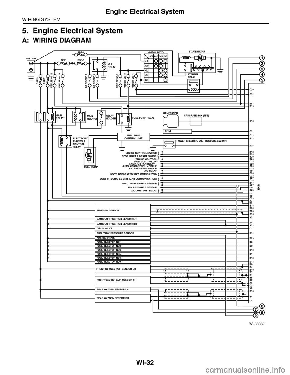
5. Engine Electrical System
A: WIRING DIAGRAM
WI-08039
678
1
2
3
4
5
C20
C32
C31
B5B19
B33
A33
C10
ECMC1B25C8A27
C21C23A7
D29
B2
BATTERY
M/B FUSE NO. 11SBF-7
SBF
SBF-5
SBF-8
SBF-6
STARTERRELAY
IG 2RELAY
IGNITION SWITCHOFF+B
ACC
IG2
IG1
ACCONST
ST
STARTER MOTOR
MAINRELAY 1
ELECTRONICTHROTTLECONTROLRELAY
FUEL PUMP RELAY
FUEL PUMP
FUEL PUMPCONTROL UNIT
MAINRELAY 2RELAYHOLDER
A21
A11A22
B34
B35
B7B6
B11B10
B9B8
C2
B26AIR FLOW SENSOR
CAMSHAFT POSITION SENSOR LH
CPC SOLENOID
B1
C3C5B15
B4C4
POWER STEERING OIL PRESSURE SWITCH
C12
MAIN FUSE BOX (M/B)GENERATOR
B18
TCM
D8FUEL INJECTOR NO.1D9D10D11
PWM CONTROLLORAUTO A/C CONTROL MODULE
A/C RELAY
BODY INTEGRATED UNIT (CAN COMMUNICATION)
FUEL TEMPERATURE SENSOR
VACUUM PUMP RELAY
BODY INTEGRATED UNIT (IMMOBILIZER)
C18C29C24C33
C27
B24B12
B20B28
C26C34
C35B17
CRUISE CONTROL SWITCH
FUEL INJECTOR NO.2FUEL INJECTOR NO.3
C17DRAIN VALVE
FUEL INJECTOR NO.4D12D13FUEL INJECTOR NO.5FUEL INJECTOR NO.6
FRONT OXYGEN (A/F) SENSOR RH
REAR OXYGEN SENSOR RH
REAR OXYGEN SENSOR LH
FRONT OXYGEN (A/F) SENSOR LH
A/C PRESSURE SWITCH
M/V PRESSURE SENSOR
RADIATOR FAN RELAY 1
STOP LIGHT & BRAKE SWITCH(CRUISE CONTROL)
C9
FUEL TANK PRESSURE SENSORB32
M/B FUSE NO. 13F/B FUSE NO. 7F/B FUSE NO. 4F/B FUSE NO. 5F/B FUSE NO. 12F/B FUSE NO. 21
CAMSHAFT POSITION SENSOR RH
9
Page 2318 of 2453

WI-34
Engine Electrical System
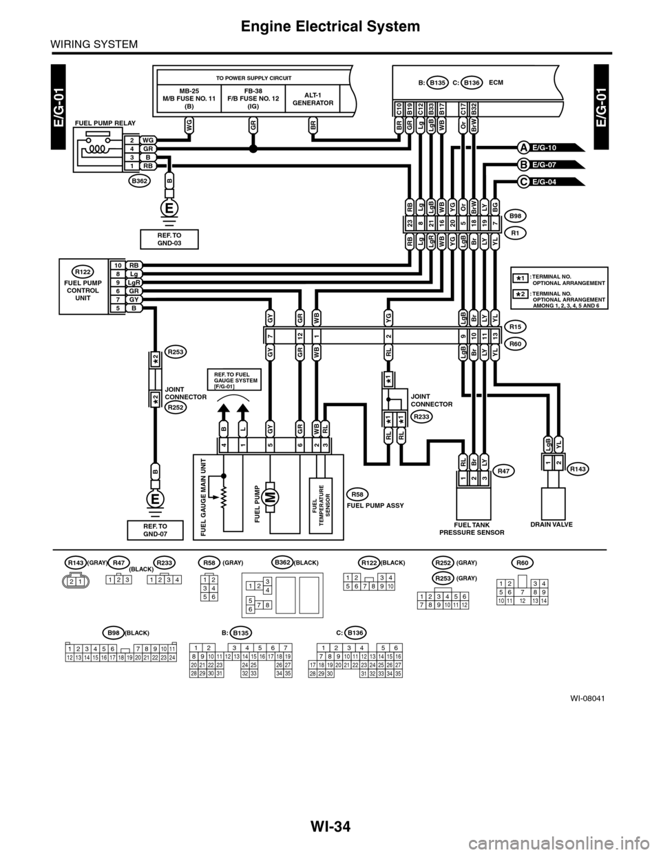
WIRING SYSTEM
WI-08041
E/G-01E/G-01
R15
R60
B98
R1
MB-25M/B FUSE NO. 11(B)
FB-38F/B FUSE NO. 12(IG)
ALT-1GENERATOR
TO POWER SUPPLY CIRCUIT
WGGRBR
C10
ECMB135B:B136C:
BR
C12
Lg
B19
GR
B33
LgB
B17B32
E/G-10A
E/G-07B
E/G-04C
R47R58
123214365
91011
YL
13
RL
1
BrLYR4723
LgBYL
R143
B
WGGR24B3RB1
B362
FUEL PUMP RELAY
RBLg108LgR9GR6GY7B5
R122
FUEL PUMPCONTROLUNIT
DRAIN VALVEFUEL TANKPRESSURE SENSOR
WB 16YG
20
LgB
5
Br
18
RB
23
Lg
8
LgR
21
LY
19
LgBBrLY
LgB
2
YG
RLBrLY
YL
YL
7
BGLgLgBRB
R122
12345678910
12
R143
21
WBBrW
C17
Or
WBYGOrBrWLY
REF. TOGND-03
B
REF. TOGND-07
C:B136
16101112131415252430
9871718192028212223293231
123456
2726333435
B135B:
5672134
29
101112131415252416
30
98171819202821222332312627333435
B362
12
78
3456
235641
WBRLGYGR
WBGYGR
BL
R58
12
WB
1
FUEL PUMP ASSY
FUEL PUMPFUEL
TEMPERATURE SENSOR
FUEL GAUGE MAIN UNIT
7
REF. TO FUELGAUGE SYSTEM[F/G-01]
GRGY
RL
JOINTCONNECTOR
R233
RL
B98(BLACK)
(BLACK)
R253
123456789121011
(GRAY)
R252(GRAY)(BLACK)(GRAY)(BLACK)(GRAY)
123456 78910 1112 13 16 1714 15 18 19 2021222324
R60
12
10115634897131412
R233
1234
*1
*1*1
*1: TERMINAL NO. OPTIONAL ARRANGEMENT
JOINTCONNECTORR252
R2532*
2*
: TERMINAL NO. OPTIONAL ARRANGEMENT AMONG 1, 2, 3, 4, 5 AND 6
2*
Page 2365 of 2453
WI-81
Charging System
WIRING SYSTEM
18.Charging System
A: WIRING DIAGRAM
WI-08087
CHG-01CHG-01
F37A:
GENERATOR
BR
3
WB
1
WR
2W
REF. TO POWER SUPPLYCIRCUIT [P-SUP-02]
F26
i10A:
i11B:
COMBINATIONMETER
B9
BW
WB
B11
A7
B228
REF. TO ENGINGEELECTRICAL SYSTEM[E/G-01]
OP CONNECTOR
MAIN FUSE BOX(M/B)
13
F37
B143
A:
B:
F26
123
B228
131415
123456789101112
CHARGEWARNINGLIGHT
1234 5678910 11 12 13 14 15 16 17 18 19 20
B143B:
12345678910 11 12 13 14 15 16 17 18 19 20
L
L
i1
B40321
L
BW
TO POWER SUPPLY CIRCUIT
FB-36 F/B FUSE NO. 5 (IG)
123456789101112
i127(BLACK)
i126(BLACK)
i10
19 20 2115 16 17 18222324252627282930123456 8910 11 12 13 147
A:
BrW
A3A4
BrW
BrW
JOINT CONNECTOR
i126i127
1*
2*2*
i11
123 45678910 11 12 13 14
B:
567821943
10
2422 23 25
11121314151617181920 21
B403
: TERMINAL NO. OPTIONAL ARRANGEMENT AMONG 10, 11 AND 12
: TERMINAL NO. OPTIONAL ARRANGEMENT AMONG 7, 8 AND 9
1*
2*
Page 2416 of 2453
WI-132
Combination Meter System
WIRING SYSTEM
WI-08134
METER-02METER-02
ECM
TPM
CONTROL M
ODULE
VDC CONTROL M
ODULE
OIL P
RESSURE SW
ITCH
GENERATOR
BRAKE FLU
ID LEV
EL SWITCH
AIRBAG WARNING LIGHT
HEADLIGHT RELAYAIRBAG CONTROLMODULE
ABS WARNING LIGHT
CHARGE WARNING LIGHTPARKING BRAKE/BRAKE FLUIDLEVEL WARNING LIGHT
VDC CONTROL M
ODULE
PARKING BRAKE SWITCH
REAR DIFFE
RENTIAL
PRESSURE SWITCH
SEA
T BELT W
ARNING LIG
HT
SEAT BELT S
WITCH
A3
IGNITION SWITCH (IG)
A4
REVERSECIRCUIT
OIL PRESSUREWARNING LIGHT
MALFUNCTION INDICATOR LIGHT
HI-BEAM INDICATOR LIGHT
TURN SIGNAL &HAZARD MODULE
TURN SIGNALINDICATOR LIGHT LHTURN SIGNALINDICATOR LIGHT RH
REVERSECIRCUIT
REVERSECIRCUIT
B
B3A14B1B12
METER-03A
BATTERY
B8B7B9B6B10B5B4B11
REAR DIFFERENTIAL OIL TEMPERATURE WARNING LIGHT
REVERSECIRCUIT
DIMMER SWITCH
TIRE INFLATION PRESSURE WARNING LIGHT
REVERSECIRCUIT
A10A7