Page 1576 of 2453
FU(H6DO)-15
Intake Manifold
FUEL INJECTION (FUEL SYSTEMS)
11) Connect the engine coolant hoses to throttle
body.
12) Connect the connector to throttle body.
13) Install the generator.
INSTALLATION, Generator.>
14) Install the air cleaner case and air intake cham-
ber.
Cleaner Case.>
TION, Air Intake Chamber.>
15) Install the fuse of fuel pump to main fuse box.
16) Connect the ground cable to the battery.
17) Install the collector cover.
C: DISASSEMBLY
1) Remove the engine harness from intake mani-
fold.
2) Remove the throttle body.
11, REMOVAL, Throttle Body.>
3) Remove the manifold absolute pressure sensor.
solute Pressure Sensor.>
4) Remove the purge control solenoid valve.
to EC(H6DO)-6, REMOVAL, Purge Control Sole-
noid Valve.>
5) Loosen the clamp which holds fuel injector pipe
to fuel hose, and then disconnect the pipe from fuel
hose.
6) Remove the bolts which install fuel pipes on in-
take manifold.
FU-02114
FU-02487FU-02124
FU-02125
FU-02126
Page 1580 of 2453
FU(H6DO)-19
Camshaft Position Sensor
FUEL INJECTION (FUEL SYSTEMS)
6. Camshaft Position Sensor
A: REMOVAL
1) Remove the collector cover.
2) Disconnect the ground cable from battery.
3) Remove the generator harness from fuel pipe
protector LH.
4) Remove the fuel pipe protector LH.
5) Disconnect the connector from camshaft posi-
tion sensor LH.
6) Remove the camshaft position sensor LH.
7) Remove the camshaft position sensor RH in the
same procedure as LH.
B: INSTALLATION
Install in the reverse order of removal.
Tightening torque:
Camshaft position sensor
6.4 N·m (0.65 kgf-m, 4.7 ft-lb)
Fuel pipe protector
19 N·m (1.9 kgf-m, 14 ft-lb)
FU-02117
FU-02129
FU-02130
Page 1585 of 2453

FU(H6DO)-24
Fuel Injector
FUEL INJECTION (FUEL SYSTEMS)
11.Fuel Injector
A: REMOVAL
1. RH SIDE
1) Remove the collector cover.
2) Release the fuel pressure.
37, RELEASING OF FUEL PRESSURE, PROCE-
DURE, Fuel.>
3) Disconnect the ground cable from battery.
4) Open the fuel filler flap lid, and remove the fuel
filler cap.
5) Remove the air cleaner case.
IN(H6DO)-5, REMOVAL, Air Cleaner Case.>
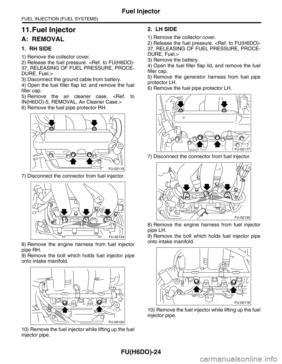
6) Remove the fuel pipe protector RH.
7) Disconnect the connector from fuel injector.
8) Remove the engine harness from fuel injector
pipe RH.
9) Remove the bolt which holds fuel injector pipe
onto intake manifold.
10) Remove the fuel injector while lifting up the fuel
injector pipe.
2. LH SIDE
1) Remove the collector cover.
2) Release the fuel pressure.
37, RELEASING OF FUEL PRESSURE, PROCE-
DURE, Fuel.>
3) Remove the battery.
4) Open the fuel filler flap lid, and remove the fuel
filler cap.
5) Remove the generator harness from fuel pipe
protector LH.
6) Remove the fuel pipe protector LH.
7) Disconnect the connector from fuel injector.
8) Remove the engine harness from fuel injector
pipe LH.
9) Remove the bolt which holds fuel injector pipe
onto intake manifold.
10) Remove the fuel injector while lifting up the fuel
injector pipe.
FU-02119
FU-02134
FU-02120
FU-02117
FU-02135
FU-02118
Page 1871 of 2453
ME(H6DO)-5
General Description
MECHANICAL
B: COMPONENT
1. V-BELT
(1) V-belt (6) Generator plateTightening torque: N·m (kgf-m, ft-lb)
(2) Collector cover bracket (7) A/C compressor stayT1: 6.4 (0.65, 4.7)
(3) Belt tension adjuster ASSY (8) Idler pulleyT2: 20 (2.0, 14)
(4) Power steering pump bracket (9) Idler pulley coverT3: 25 (2.5, 18)
(5) GeneratorT4: 33 (3.4, 24.3)
Page 1897 of 2453
ME(H6DO)-31
V-belt
MECHANICAL
9. V-belt
A: REMOVAL
1) Install the tool to belt tension adjuster assembly
installation bolt.
2) Rotate the tool clockwise and loosen the V-belt
to remove.
3) Remove the V-belt cover.
B: INSTALLATION
Install in the reverse order of removal.
C: INSPECTION
1) Replace the V-belt, if cracks, fraying or wear is
found.
2) Make sure that the V-belt automatic belt tension
indicator (A) is within the range (D).
(1) Power steering oil pump pulley
(2) Belt tension adjuster ASSY
(3) Crank pulley
(4) A/C compressor
(5) Belt idler
(6) Generator
ME-00473
(1)(6)
(4)
(5)(2)
(3)ME-00474
(A) Indicator
(B) Generator
(C) Power steering oil pump pulley
(D) Service limit
(B)
(A)
(D)
(C)
ME-00475
Page 1898 of 2453

ME(H6DO)-32
Engine Assembly
MECHANICAL
10.Engine Assembly
A: REMOVAL
1) Set the vehicle on a lift.
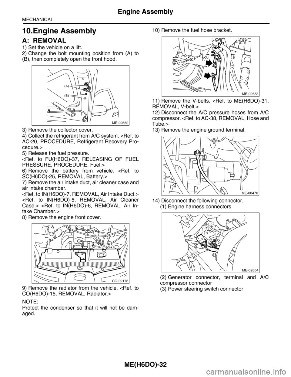
2) Change the bolt mounting position from (A) to
(B), then completely open the front hood.
3) Remove the collector cover.
4) Collect the refrigerant from A/C system.
AC-20, PROCEDURE, Refrigerant Recovery Pro-
cedure.>
5) Release the fuel pressure.
PRESSURE, PROCEDURE, Fuel.>
6) Remove the battery from vehicle.
SC(H6DO)-25, REMOVAL, Battery.>
7) Remove the air intake duct, air cleaner case and
air intake chamber.
Case.>
take Chamber.>
8) Remove the engine front cover.
9) Remove the radiator from the vehicle.
CO(H6DO)-15, REMOVAL, Radiator.>
NOTE:
Protect the condenser so that it will not be dam-
aged.
10) Remove the fuel hose bracket.
11) Remove the V-belts.
REMOVAL, V-belt.>
12) Disconnect the A/C pressure hoses from A/C
compressor.
Tube.>
13) Remove the engine ground terminal.
14) Disconnect the following connector.
(1) Engine harness connectors
(2) Generator connector, terminal and A/C
compressor connector
(3) Power steering switch connector
ME-02652
(A)
(B)
CO-02176
ME-02653
ME-00476
ME-02654
Page 1904 of 2453

ME(H6DO)-38
Engine Assembly
MECHANICAL
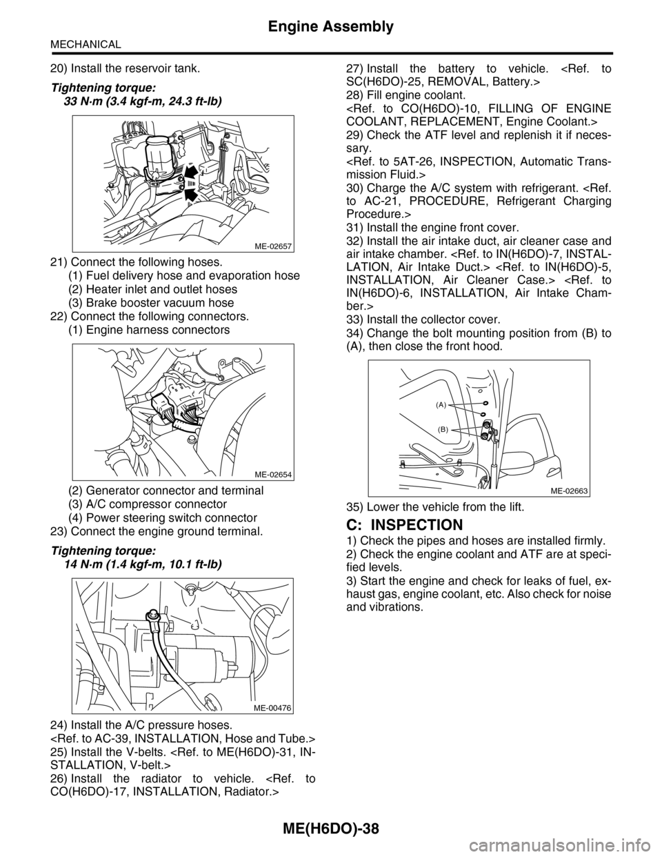
20) Install the reservoir tank.
Tightening torque:
33 N·m (3.4 kgf-m, 24.3 ft-lb)
21) Connect the following hoses.
(1) Fuel delivery hose and evaporation hose
(2) Heater inlet and outlet hoses
(3) Brake booster vacuum hose
22) Connect the following connectors.
(1) Engine harness connectors
(2) Generator connector and terminal
(3) A/C compressor connector
(4) Power steering switch connector
23) Connect the engine ground terminal.
Tightening torque:
14 N·m (1.4 kgf-m, 10.1 ft-lb)
24) Install the A/C pressure hoses.
25) Install the V-belts.
STALLATION, V-belt.>
26) Install the radiator to vehicle.
CO(H6DO)-17, INSTALLATION, Radiator.>
27) Install the battery to vehicle.
SC(H6DO)-25, REMOVAL, Battery.>
28) Fill engine coolant.
COOLANT, REPLACEMENT, Engine Coolant.>
29) Check the ATF level and replenish it if neces-
sary.
mission Fluid.>
30) Charge the A/C system with refrigerant.
to AC-21, PROCEDURE, Refrigerant Charging
Procedure.>
31) Install the engine front cover.
32) Install the air intake duct, air cleaner case and
air intake chamber.
LATION, Air Intake Duct.>
INSTALLATION, Air Cleaner Case.>
IN(H6DO)-6, INSTALLATION, Air Intake Cham-
ber.>
33) Install the collector cover.
34) Change the bolt mounting position from (B) to
(A), then close the front hood.
35) Lower the vehicle from the lift.
C: INSPECTION
1) Check the pipes and hoses are installed firmly.
2) Check the engine coolant and ATF are at speci-
fied levels.
3) Start the engine and check for leaks of fuel, ex-
haust gas, engine coolant, etc. Also check for noise
and vibrations.
ME-02657
ME-02654
ME-00476
ME-02663
(A)
(B)
Page 1906 of 2453

ME(H6DO)-40
Preparation for Overhaul
MECHANICAL
12.Preparation for Overhaul
A: REMOVAL
1) Remove the engine assembly from the body.
sembly.>
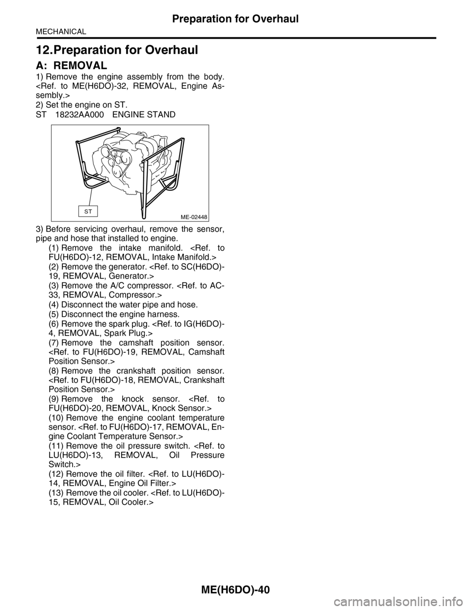
2) Set the engine on ST.
ST 18232AA000 ENGINE STAND
3) Before servicing overhaul, remove the sensor,
pipe and hose that installed to engine.
(1) Remove the intake manifold.
FU(H6DO)-12, REMOVAL, Intake Manifold.>
(2) Remove the generator.
19, REMOVAL, Generator.>
(3) Remove the A/C compressor.
33, REMOVAL, Compressor.>
(4) Disconnect the water pipe and hose.
(5) Disconnect the engine harness.
(6) Remove the spark plug.
4, REMOVAL, Spark Plug.>
(7) Remove the camshaft position sensor.
Position Sensor.>
(8) Remove the crankshaft position sensor.
Position Sensor.>
(9) Remove the knock sensor.
FU(H6DO)-20, REMOVAL, Knock Sensor.>
(10) Remove the engine coolant temperature
sensor.
gine Coolant Temperature Sensor.>
(11) Remove the oil pressure switch.
LU(H6DO)-13, REMOVAL, Oil Pressure
Switch.>
(12) Remove the oil filter.
14, REMOVAL, Engine Oil Filter.>
(13) Remove the oil cooler.
15, REMOVAL, Oil Cooler.>
STME-02448