Page 1956 of 2453

ME(H6DO)-90
Engine Noise
MECHANICAL
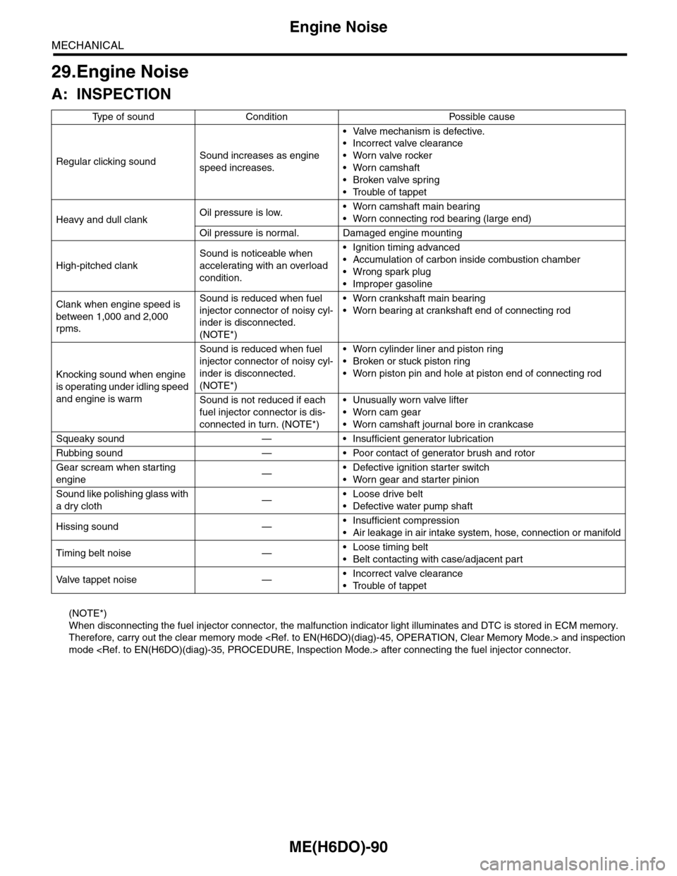
29.Engine Noise
A: INSPECTION
(NOTE*)
When disconnecting the fuel injector connector, the malfunction indicator light illuminates and DTC is stored in ECM memory.
Therefore, carry out the clear memory mode and inspection
mode after connecting the fuel injector connector.
Ty p e o f s o u n d C o n d i t i o n P o s s i b l e c a u s e
Regular clicking soundSound increases as engine
speed increases.
•Valve mechanism is defective.
•Incorrect valve clearance
•Worn valve rocker
•Worn camshaft
•Broken valve spring
•Trouble of tappet
Heavy and dull clankOil pressure is low.•Worn camshaft main bearing
•Worn connecting rod bearing (large end)
Oil pressure is normal. Damaged engine mounting
High-pitched clank
Sound is noticeable when
accelerating with an overload
condition.
•Ignition timing advanced
•Accumulation of carbon inside combustion chamber
•Wrong spark plug
•Improper gasoline
Clank when engine speed is
between 1,000 and 2,000
rpms.
Sound is reduced when fuel
injector connector of noisy cyl-
inder is disconnected.
(NOTE*)
•Worn crankshaft main bearing
•Worn bearing at crankshaft end of connecting rod
Knocking sound when engine
is operating under idling speed
and engine is warm
Sound is reduced when fuel
injector connector of noisy cyl-
inder is disconnected.
(NOTE*)
•Worn cylinder liner and piston ring
•Broken or stuck piston ring
•Worn piston pin and hole at piston end of connecting rod
Sound is not reduced if each
fuel injector connector is dis-
connected in turn. (NOTE*)
•Unusually worn valve lifter
•Worn cam gear
•Worn camshaft journal bore in crankcase
Squeaky sound — • Insufficient generator lubrication
Rubbing sound — • Poor contact of generator brush and rotor
Gear scream when starting
engine—•Defective ignition starter switch
•Worn gear and starter pinion
Sound like polishing glass with
a dry cloth—•Loose drive belt
•Defective water pump shaft
Hissing sound —•Insufficient compression
•Air leakage in air intake system, hose, connection or manifold
Timing belt noise —•Loose timing belt
•Belt contacting with case/adjacent part
Va l ve t a p p e t n o i s e —•Incorrect valve clearance
•Trouble of tappet
Page 1960 of 2453

SC(H6DO)-2
General Description
STARTING/CHARGING SYSTEMS
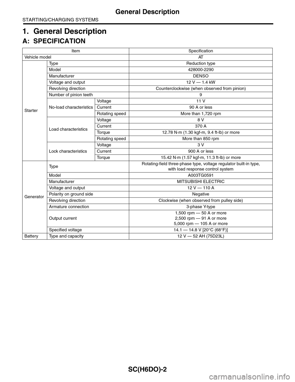
1. General Description
A: SPECIFICATION
Item Specification
Ve h i c l e m o d e lAT
Starter
Ty p e R e d u c t i o n t y p e
Model 428000-2290
Manufacturer DENSO
Vo l t a g e a n d o u t p u t 1 2 V — 1 . 4 k W
Revolving direction Counterclockwise (when observed from pinion)
Number of pinion teeth 9
No-load characteristics
Vo l t a g e 1 1 V
Current 90 A or less
Rotating speed More than 1,720 rpm
Load characteristics
Vo l t a g e 8 V
Current 370 A
To r q u e 1 2 . 7 8 N · m ( 1 . 3 0 k g f - m , 9 . 4 f t - l b ) o r m o r e
Rotating speed More than 850 rpm
Lock characteristics
Vo l t a g e 3 V
Current 900 A or less
To r q u e 1 5 . 4 2 N · m ( 1 . 5 7 k g f - m , 1 1 . 3 f t - l b ) o r m o r e
Generator
Ty p eRotating-field three-phase type, voltage regulator built-in type,
with load response control system
Model A003TG0591
Manufacturer MITSUBISHI ELECTRIC
Vo l t a g e a n d o u t p u t 1 2 V — 1 1 0 A
Po la r i t y on gr ou n d s id e N e g at i ve
Revolving direction Clockwise (when observed from pulley side)
Armature connection 3-phase Y-type
Output current
1,500 rpm — 50 A or more
2,500 rpm — 91 A or more
5,000 rpm — 105 A or more
Specified voltage 14.1 — 14.8 V [20°C (68°F)]
Battery Type and capacity 12 V — 52 AH (75D23L)
Page 1962 of 2453
SC(H6DO)-4
General Description
STARTING/CHARGING SYSTEMS
2. GENERATOR
(1) Pulley nut (7) Bearing (13) Terminals
(2) Pulley (8) Stator coil
(3) Front cover (9) IC regulator with brushTightening torque: N·m (kgf-m, ft-lb)
(4) Ball bearing (10) BrushT1: 3.9 (0.4, 2.9)
(5) Bearing retainer (11) RectifierT2: 4.6 (0.47, 3.4)
(6) Rotor (12) Rear coverT3: 103 (10.5, 76)
Page 1977 of 2453
SC(H6DO)-19
Generator
STARTING/CHARGING SYSTEMS
3. Generator
A: REMOVAL
1) Remove the collector cover.
2) Disconnect the ground cable from battery.
3) Disconnect the connector and terminal from
generator.
4) Remove the V-belts.
REMOVAL, V-belt.>
5) Remove the bolts which install the generator
onto bracket.
B: INSTALLATION
Install in the reverse order of removal.
Tightening torque:
25 N·m (2.5 kgf-m, 18.1 ft-lb)
CAUTION:
Check and adjust the V-belt tension.
C: DISASSEMBLY
1) Remove the four through-bolts.
2) Heat the portion (A) of rear cover to 50°C
(122°F) with a heater drier.
3) Then insert the tip of a flat tip screwdriver into the
gap between stator core and front cover. Pry them
apart to disassemble.
4) Hold the rotor with a vise and remove pulley nut.
SC-02003
SC-02098
SC-02098
(A) Screwdriver
SC-00078
SC-00079
(A)
SC-00080
(A)
(A)
SC-00035
Page 1978 of 2453
SC(H6DO)-20
Generator
STARTING/CHARGING SYSTEMS
CAUTION:
When holding the rotor with a vise, place alumi-
num plates or wooden pieces on the vise jaws
to prevent rotor from damage.
5) Remove the ball bearing as follows.
(1) Remove the bolt, and then remove the bear-
ing retainer.
(2) Firmly install an appropriate tool (such as a
fit socket wrench) to bearing inner race.
(3) Push the ball bearing off the front cover us-
ing a press.
6) Remove the bearing from rotor using a bearing
puller.
7) Separate the connection between rectifier and
stator coil to remove stator coil.
CAUTION:
Do not allow a 180 — 270 W soldering iron to
contact the terminals for more than 5 seconds
at once because the rectifier cannot withstand
so much heat.
8) Remove the IC regulator as follows.
(1) Remove the screws which secure IC regula-
tor to rear cover.
(A) Front cover
(B) Pulley
(C) Nut
(D) Rotor
(A)
(B)
(C)
(D)SC-00036
SC-00081
SC-00082
SC-00046
SC-00083
SC-00084
Page 1979 of 2453
SC(H6DO)-21
Generator
STARTING/CHARGING SYSTEMS
(2) Unsolder the connection between IC regula-
tor and rectifier to remove IC regulator.
9) Remove the brush as follows.
(1) Remove the cover A.
(2) Remove the cover B.
(3) Separate the brush from connection to re-
move.
10) Remove the rectifier as follows.
(1) Remove the bolts which secure rectifier.
(2) Remove the cover of terminal B.
(3) Remove the nut of terminal B, and then re-
move the rectifier.(A) Cover A
(A) Cover B
SC-00085
SC-00086
(A)
SC-00087
(A)
SC-00088
SC-00089
SC-00090
SC-00091
Page 1980 of 2453

SC(H6DO)-22
Generator
STARTING/CHARGING SYSTEMS
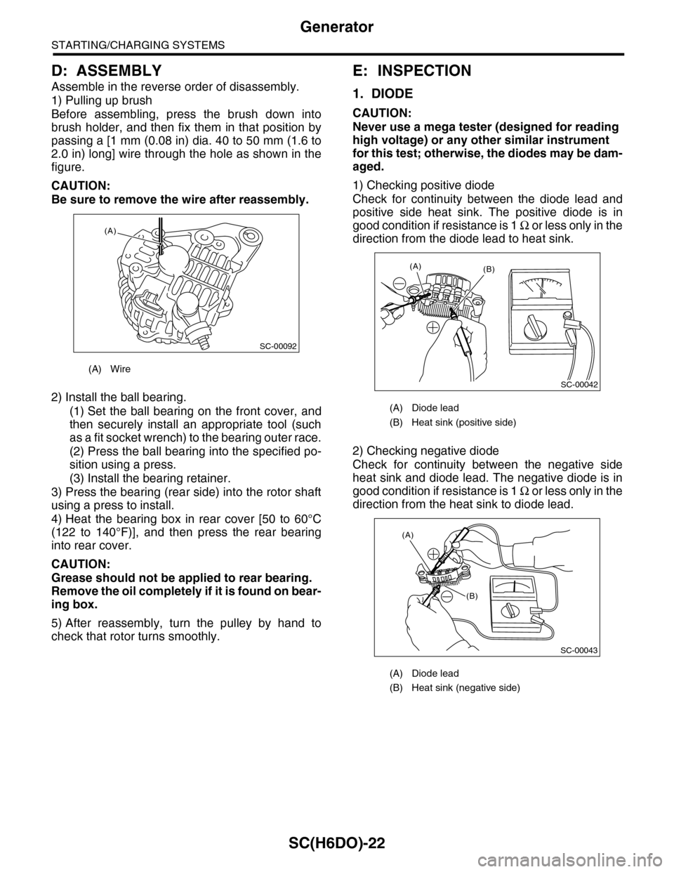
D: ASSEMBLY
Assemble in the reverse order of disassembly.
1) Pulling up brush
Before assembling, press the brush down into
brush holder, and then fix them in that position by
passing a [1 mm (0.08 in) dia. 40 to 50 mm (1.6 to
2.0 in) long] wire through the hole as shown in the
figure.
CAUTION:
Be sure to remove the wire after reassembly.
2) Install the ball bearing.
(1) Set the ball bearing on the front cover, and
then securely install an appropriate tool (such
as a fit socket wrench) to the bearing outer race.
(2) Press the ball bearing into the specified po-
sition using a press.
(3) Install the bearing retainer.
3) Press the bearing (rear side) into the rotor shaft
using a press to install.
4) Heat the bearing box in rear cover [50 to 60°C
(122 to 140°F)], and then press the rear bearing
into rear cover.
CAUTION:
Grease should not be applied to rear bearing.
Remove the oil completely if it is found on bear-
ing box.
5) After reassembly, turn the pulley by hand to
check that rotor turns smoothly.
E: INSPECTION
1. DIODE
CAUTION:
Never use a mega tester (designed for reading
high voltage) or any other similar instrument
for this test; otherwise, the diodes may be dam-
aged.
1) Checking positive diode
Check for continuity between the diode lead and
positive side heat sink. The positive diode is in
good condition if resistance is 1 Ω o r l e s s o n l y i n t h e
direction from the diode lead to heat sink.
2) Checking negative diode
Check for continuity between the negative side
heat sink and diode lead. The negative diode is in
good condition if resistance is 1 Ω o r l e s s o n l y i n t h e
direction from the heat sink to diode lead.
(A) Wire
SC-00092
(A)
(A) Diode lead
(B) Heat sink (positive side)
(A) Diode lead
(B) Heat sink (negative side)
SC-00042
(B)(A)
(A)
(B)
SC-00043
Page 1981 of 2453

SC(H6DO)-23
Generator
STARTING/CHARGING SYSTEMS
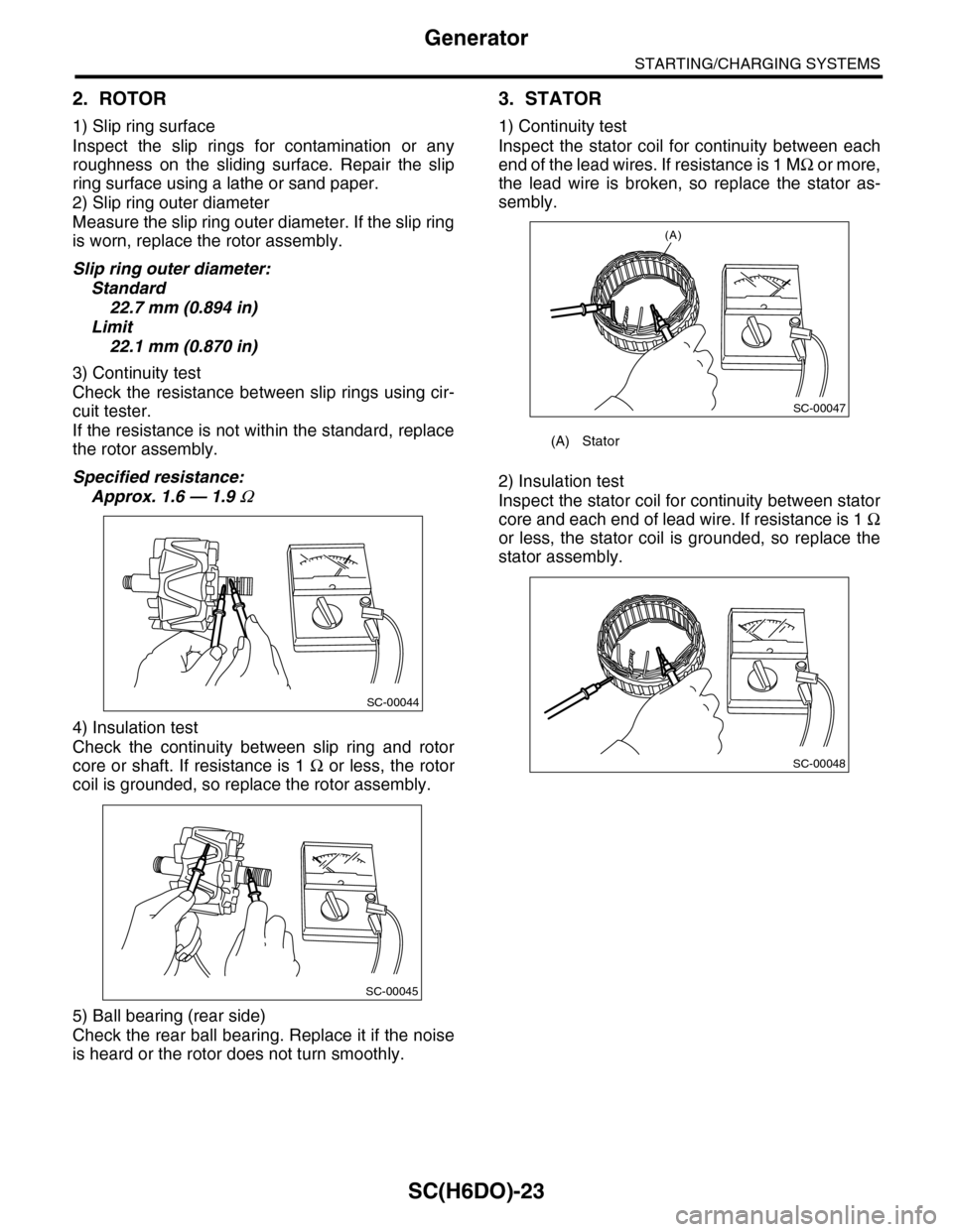
2. ROTOR
1) Slip ring surface
Inspect the slip rings for contamination or any
roughness on the sliding surface. Repair the slip
ring surface using a lathe or sand paper.
2) Slip ring outer diameter
Measure the slip ring outer diameter. If the slip ring
is worn, replace the rotor assembly.
Slip ring outer diameter:
Standard
22.7 mm (0.894 in)
Limit
22.1 mm (0.870 in)
3) Continuity test
Check the resistance between slip rings using cir-
cuit tester.
If the resistance is not within the standard, replace
the rotor assembly.
Specified resistance:
Approx. 1.6 — 1.9 Ω
4) Insulation test
Check the continuity between slip ring and rotor
core or shaft. If resistance is 1 Ω or less, the rotor
coil is grounded, so replace the rotor assembly.
5) Ball bearing (rear side)
Check the rear ball bearing. Replace it if the noise
is heard or the rotor does not turn smoothly.
3. STATOR
1) Continuity test
Inspect the stator coil for continuity between each
end of the lead wires. If resistance is 1 MΩ o r m o r e ,
the lead wire is broken, so replace the stator as-
sembly.
2) Insulation test
Inspect the stator coil for continuity between stator
core and each end of lead wire. If resistance is 1 Ω
or less, the stator coil is grounded, so replace the
stator assembly.
SC-00044
SC-00045
(A) Stator
(A)
SC-00047
SC-00048