Page 129 of 224
 Owners Manual Transporting children safely
128
passenger seat where the child is seated
with its back facing in direction of
travel (in some countries also when the
child is facing the direction of travel).
�")
Transporting children safely
128
passenger seat where the child is seated
with its back facing in direction of
travel (in some countries also when the
child is facing the direction of travel).
− in a specialist garage − or by using the switch for
the front passenger airbag*
⇒page 121.
•
In certain countries national legal provisions require that besides the
front passenger airbag also the front pa
ssenger side airbag is deactivated.
Please comply with any differing nati
onal legal regulations regarding the
use of child safety seats.•
If this is not done, a child seated on the front passenger seat may suffer
severe or even fatal injuries if the
front passenger airbag or airbags are
deployed.•
You should have the front passenger ai
rbag (or airbags) reactivated just
as soon as you no longer use a child sa
fety seat on the front passenger seat.
Child safety seats in Group 2For children up to about 7 years of age
weighing between 15 and 25 kg the optimal
solution is a child safety seat in comb
ination with the three-point seat belt
⇒ fig. 135
.
WARNING
•
When transporting a child on the front passenger seat, please comply
with the appropriate national regulati
ons regarding the use of child safety
seats. If required, the airbag has to be deactivated,
− in a specialist garage − or by using the switch for the front passenger airbag*
⇒page 121.
•
The shoulder part of the seat belt
must run approximately across the
middle of the shoulder and fit snugly agai
nst the chest. It must on no account
run across the neck. The lap part of the seat belt must run across the pelvis and fits snugly; it must not run over the belly. Tighten the belt webbing over your hip if necessary.•
Please comply with any differing nati
onal legal regulations regarding the
use of child safety seats.Child safety seats in Group 3For children of about 7 years of age weighi
ng between 22 and 36 kg and of a height
of less than 150 cm, the optimal solution
is a child safety seat (seat bolster) in
combination with the three-point seat belt
⇒fig. 136
.
Children of more than 150 cm in height may use the seat belts fitted to the vehicle without a seat bolster.
WARNING (continued)
Fig. 135 Child seat in Group 2 installed on the rear seat facing the direction of travel
Fig. 136 Child seat in Group 3 installed on the rear seat facing the direction of travel
s2g8.b.book Page 128 Tuesday, April 7, 2009 8:53 AM
Page 130 of 224
 Owners Manual Transporting children safely
129
Using the system
Safety
Driving Tips
General Maintenance
Breakdown assistance
Technical Data
WARNING
•
When transporting a child on the front passenger seat, please")
Transporting children safely
129
Using the system
Safety
Driving Tips
General Maintenance
Breakdown assistance
Technical Data
WARNING
•
When transporting a child on the front passenger seat, please comply
with the appropriate national regulations regarding the use of child safety seats. If required, the airb
ag has to be deactivated,
− in a specialist garage − or by using the switch for the front passenger airbag*
⇒page 121.
•
The shoulder part of the seat belt must run approximately across the
middle of the shoulder and fit snugly against the chest. It must on no account run across the neck. The lap part of the seat belt must run across the pelvis and fits snugly; it must not run over th
e belly. Tighten the belt webbing over
your hip if necessary.•
Please comply with any differing nati
onal legal regulations regarding the
use of child safety seats.Attaching a child seat us
ing the “ISOFIX” system
There are two locking eyes between th
e rear exterior seat backrest and
the surface of the seat itself
on both sides for fixing the
ISOFIX
system
child seat in place. One can mount
a child safety seat using the
ISOFIX
system quickly, easily and reliably.
The installation must be carried out
according to the supplied instructions. The seat must click into place audibly when installing. Install child seat – Insert the mounting funnels onto the locking eyes between the seat
backrest and the seat cushion
⇒
fig. 137
.
– Push the notched arms of the chil
d seat over the mounting funnels
into the locking eyes, until it is heard to lock
⇒
fig. 138
.
–
Pull on both sides of the child seat!
One can mount a child safety seat using the “ISOFIX” system quickly, easily and reli- ably. Please pay close attention to instruct
ions from the manufacturer of the child
safety seat when installing and removing the seat. Child seats fitted with the “ISOFIX” syst
em can only be mounted and fixed in a
vehicle fitted with an “ISOFIX” system when
these child seats have been released for
this type of vehicle according to the ECE-R 44 standard. You can obtain child seats with the “ISOFIX” attachment system from specialist garages who will also installed it as well.
Fig. 137 Locking eyes (ISOFIX system)
Fig. 138 The ISOFIX child seat is pushed into the mounting funnels
s2g8.b.book Page 129 Tuesday, April 7, 2009 8:53 AM
Page 131 of 224
Transporting children safely
130
Complete installation instructions are
enclosed with the child safety seat.
WARNING
•
The locking eyes have just been de
veloped for child safety seats which
use the “ISOFIX” system. You should
therefore never attach other child
safety seats, seat belts or obje
cts to the locking eyes - hazard!
•
Ask a specialist garage whether a
child seat which you bought for
another vehicle is recommended for use in your vehicle before using a child seat with “ISOFIX” system.•
Certain child seats which use the “ISOFIX” system can be attached with
standard three-point seat belts. Please pay close attention to instructions from the manufacturer of the child safety seat when installing and removing the seat.
Note
•
Child seats which use the “ISOFIX” system are currently available for children
weighing from 9 up to 18 kg. This correspo
nds to an age range of from 9 months to
4 years.s2g8.b.book Page 130 Tuesday, April 7, 2009 8:53 AM
Page 132 of 224
 Owners Manual Intelligent Technology
131
Using the system
Safety
Driving Tips
General Maintenance
Breakdown assistance
Technical Data
Driving TipsIntelligent TechnologyElectronic stability programme (ESP)*GeneralGe")
Intelligent Technology
131
Using the system
Safety
Driving Tips
General Maintenance
Breakdown assistance
Technical Data
Driving TipsIntelligent TechnologyElectronic stability programme (ESP)*GeneralGeneral The ESP aids you maintain control of your vehicle in situations in borderline driving situations such as when negotiating a curve too fast. The risk of skidding is reduced and your vehicle thus offers greater driving stability depending on the conditions of the road surface. This occurs at all speeds. The following systems are integrated into the electronic stability programme:•
Electronic Differential Lock (EDL),
•
Traction control system (TCS),
•
Antilock brake system (ABS),
•
Brake Assist.
Operating principle The ESP switches on automatically when the engine is started and then conducts a self-test. The ESP control unit processes data from the individual systems. It also processes additional measurement data which are supplied by highly sensitive sensors: the rotational velocity of the vehi
cle about its vertical axis, the lateral accel-
eration of the vehicle, the brakin
g pressure and the steering angle.
The direction which the driver wishes to ta
ke is determined based on the steering
angle and the speed of the vehicle and is constantly compared with the actual behaviour of the vehicle. If differences exis
t, such as the vehicle beginning to skid,
the ESP will automatically brake the appropriate wheel. The car is stabilised again by the forces which take effect when the wheel is braked. Intervention into the brake system takes place primarily on the outer front wheel of a vehicle which tends to oversteer (tendency for the rear of the vehicle to break away) while occurs this is on the inner re
ar wheel of a vehicle which tends to under-
steer (tendency to shift out of the curve). This braking control cycle is accompanied by noises. The ESP operates in combination with the ABS
⇒page 135, “Antilock brake system
(ABS)*”. If there is a fault in the ABS system, the ESP also does not operate. The ESP warning light
⇒page 33 lights up in the instrument cluster when there is a
fault on the ESP. Switching off You can switch the ESP off and on again
as you wish, by pressing the button
⇒ fig. 139
. The ESP warning light
⇒page 33 lights up in the instrument cluster
when the ESP is switched off. The ESP should normally always be switched
on. It may be good practice in certain
exceptional cases, such as when you wish
to have wheel slip, to switch off the
system. Examples:
Fig. 139 ESP switch
s2g8.b.book Page 131 Tuesday, April 7, 2009 8:53 AM
Page 133 of 224
 Owners Manual Intelligent Technology
132
•
when driving with snow chains
•
when driving in deep snow or on a loose surface
•
when it is necessary to rock a vehicle when it has become stuck.
then you should s")
Intelligent Technology
132
•
when driving with snow chains
•
when driving in deep snow or on a loose surface
•
when it is necessary to rock a vehicle when it has become stuck.
then you should switch on the ESP again.
WARNING
It is also not possible for the ESP to overcome the physical limits of the vehicle. Even if a vehicle fitted with ESP you should still always adapt your style of driving to the condition of the
road surface and the traffic situation.
This particularly applies when driving on slippery and wet roads. The increased safety offered must not tempt you to take greater risks than other- wise - risk of an accident!
Note
•
All four wheels must be fitted with the same tyres in order to achieve problem-
free operation of the ESP. Differing rolling
circumferences of the tyres can lead to an
undesirable reduction in the engine output.•
Changes to vehicle (e.g. on engine, on the brakes, on chassis or another combi-
nation of tyres and wheels) can influence the function of the ESP
⇒page 179,
“Accessories, changes and replacement of parts”.Electronic Differential Lock (EDL)* The electronic differential lock pr
events an individual wheel from
slipping.Vehicles fitted with ABS*
can be equipped with electron
ic differential lock (EDL).
General The EDL makes it much easier, and sometimes at all possible, to start off, accelerate and climb a steep hill when the conditio
ns of the road surface are unfavourable.
Operating principle The EDL is activated automatically, that is
without any action on the part of the
driver. It monitors the speeds of the driven wheels with the aid of the ABS sensors. Should only
one
drive wheel begin spinning on a slippery surface there will be an
appreciable difference in the speed of the driven wheels. The EDL function brakes the slipping wheel and the differential transmits a greater driving force to the other driven wheel. This control proces
s is also accompanied by noises.
Overheating of the brakes The EDL switches off
automatically if unusually severe
stresses exist in order to
avoid excessive heat generation in the
disc brake on the wheel which is being
braked. The vehicle can continue to be driv
en and has the same characteristics as a
vehicle not fitted with EDL. The EDL switches on again
automatically as soon as the brake has cooled down.
WARNING
•
Carefully depress the accelerator when accelerating on uniformly slip-
pery road surfaces, such as ice and sn
ow. The driven wheels might still spin
despite the EDL and affect the stability
of the vehicle - risk of an accident!
•
You should always adapt your style of driving to the condition of road
surface and to the traffic situation even
when your vehicle is fitted with EDL.
The increased safety offered must not tempt you to take greater risks than otherwise - risk of an accident!
Note
•
If the ABS warning light comes on, this ma
y also indicate a fault in the EDL.
Please have the vehicle inspected as soon
as possible by a specialist garage.
•
Changes to vehicle (e.g. on engine, on the brakes, on chassis or another combi-
nation of tyres and wheels) can in
fluence the function of the EDL
⇒page 179,
“Accessories, changes and
replacement of parts”.
s2g8.b.book Page 132 Tuesday, April 7, 2009 8:53 AM
Page 134 of 224
 Owners Manual Intelligent Technology
133
Using the system
Safety
Driving Tips
General Maintenance
Breakdown assistance
Technical Data
Traction control system (TCS) The traction control system prevents
the driven")
Intelligent Technology
133
Using the system
Safety
Driving Tips
General Maintenance
Breakdown assistance
Technical Data
Traction control system (TCS) The traction control system prevents
the driven wheels from spinning
when accelerating.General The TCS makes it much easier, and sometimes at all possible, to start off, accelerate and climb a steep hill when the conditio
ns of the road surface are unfavourable.
Operating principle The TCS switches on automatically when th
e engine is started and then conducts a
self-test. The system monitors the speeds of the driven wheels with the aid of the ABS sensors. If the wheels are spinning, the force transmitted to the road surface is automatically adapted by redu
cing the engine speed. Th
is occurs at all speeds.
The TCS operates in combination with the ABS
⇒page 135, “Antilock brake system
(ABS)*”. The TCS will not function if a fault exists in the ABS system. The TCS warning light
⇒page 33 lights up in the instrument cluster when there is a
fault on the TCS. Switching off You can switch the TCS off and on again
as you wish by pressing the button
⇒ fig. 140
. The TCS warning light
⇒page 33 lights up in the instrument cluster
when the TCS is switched off.
The TCS should normally always be switched on. It may be good practice in certain exceptional cases, such as when you wish
to have wheel slip, to switch off the
system. Examples:•
when driving with snow chains
•
when driving in deep snow or on a loose surface
•
when it is necessary to rock a vehicle when it has become stuck.
then you should switch on the TCS again.
WARNING
You should always adjust your style of driving to the conditions of the road surface and the traffic situation. The increased safety offered must not tempt you to take greater risks than otherwise - risk of an accident!
Note
•
All four wheels must be fitted with the same tyres in order to achieve problem-
free operation of the TCS. Differing rolling circumferences of the tyres can lead to an undesirable reduction in the engine output.•
Changes to vehicle (e.g. on engine, on
the brakes, on chassis or another combi-
nation of tyres and wheels) can in
fluence the function of the TCS
⇒page 179,
“Accessories, changes and replacement of parts”.BrakesWhat has a negative effect on braking efficiency?Wear-and-tear Wear-and-tear to the brake pads is greatly dependent on the operating conditions of the vehicle and your style of driving. Particularly if you drive a great deal in towns and over short distances or if you adopt a sporty style of driving, it may be neces- sary to have the thickness of the brake
pads inspected at a specialist garage
between the service inspections.
Fig. 140 TCS switch
s2g8.b.book Page 133 Tuesday, April 7, 2009 8:53 AM
Page 135 of 224
 Owners Manual Intelligent Technology
134
Wet roads or road salt There may be a certain delay before the br
akes take full effect under certain condi-
tions such as when driving through water,
during heavy rain")
Intelligent Technology
134
Wet roads or road salt There may be a certain delay before the br
akes take full effect under certain condi-
tions such as when driving through water,
during heavy rain
showers or after the
vehicle has been washed in
an automatic vehicle wash, since the brake discs and
brake pads may be moist or even have a
coating of ice on them in winter. You
should dry the brakes as soon as possib
le by applying and releasing the brakes
several times. There also may be a certain delay before the
full braking efficiency is available when
driving on roads which have been treated wi
th road salt if yo
u have not used the
brakes for some considerable time beforeha
nd. The layer of salt on the brake discs
and brake pads must first be rubb
ed off when you apply the brakes.
Corrosion Corrosion on the brake discs and dirt on th
e bake pads occur if
the vehicle has been
parked for a long period and if you do
not make much use of the braking system.
We recommend cleaning the brake discs by
firmly applying the brakes at a fairly
high speed if you do not make much use of the braking system or if surface corro-sion is present
⇒
.
Faults in the brake surface If you notice that the braking distance has suddenly become longer and that the brake pedal can be depressed further, it is
possible that a brake circuit of the dual-
circuit brake system has failed. Drive, in such cases, to the nearest specialist garage without delay in order to have the problem rectified. Drive at a reduced speed while on your way to the dealer and adapt your style of driving to the higher brake pedal pressure required. Low brake fluid level An insufficient level of brake fluid may result in problems in the brake system. The level of the brake fluid is monitored electronically
⇒page 34, “Brake system
”.
WARNING
•
Only apply the brakes for the purpose of drying and cleaning the brake
discs if the traffic conditions permit this. Do not place any other road users in jeopardy.
•
When retrospectively mounting a front
spoiler, solid wheel hubs etc. one
must ensure that the air supply to the front wheel brakes is not reduced otherwise the braking sy
stem could run too hot.
•
Allow for the fact that new brake pads
do not achieve th
eir full braking
efficiency until approximately 200 kilo
metres. New brake pads must be first
“run in” before they develop their optimal friction force. You can, however, compensate for this slightly reduced
braking force by increasing the pres-
sure on the brake pedal. This guidelin
e also applies to any new brake pads
installed at a future date.
Caution
•
Never allow the brakes to ru
b by applying slig
ht pressure if you do not wish to
brake the vehicle. This causes the brakes to overheat and can also result in a longer braking distance and excessive wear.•
Before negotiating a steep downhill section, reduce your speed, shift down into
the next lower gear. This enables you to make full use of the braking power of the vehicle and reduces the strain on the brakes
. Any additional braking should be done
intermittently, not continuously.Brake boosterThe brake booster boosts the pressure which you generate with the brake pedal. The necessary pressure is only gene
rated when the engine is running.
WARNING
•
Never switch off the engine befo
re the vehicle is stationary.
•
The brake booster only operates when
the engine is running. Greater
physical effort for braking is required
when engine is swit
ched off. Because
if you do not stop as normal, this can cause an accident and severe injuries.
WARNING (continued)
s2g8.b.book Page 134 Tuesday, April 7, 2009 8:53 AM
Page 136 of 224
 Owners Manual Intelligent Technology
135
Using the system
Safety
Driving Tips
General Maintenance
Breakdown assistance
Technical Data
Antilock brake system (ABS)*ABS prevents the wheels locking when braking.General")
Intelligent Technology
135
Using the system
Safety
Driving Tips
General Maintenance
Breakdown assistance
Technical Data
Antilock brake system (ABS)*ABS prevents the wheels locking when braking.General The ABS contributes significan
tly to enhancing the active
safety of your vehicle.
Compared to a vehicle not fitted with the ABS brake system, you are able to retain optimal steering ability even during a fu
ll brake application on a slippery road
surface because the wheels do not lock up. You must not expect, however, that the br
aking distance will be shorter under all
circumstances as a result of the ABS. Th
e braking distance for example on gravel
and fresh snow, when you should anyway be driving slowly and cautiously, will be longer. Operating principle The brake pressure will be reduced on a wheel which is rotating at a speed which is too low for the speed of the vehicle and tend
ing to lock. This control cycle is notice-
able from a
pulsating movement of the brake pedal
which is accompanied by
noises. This is consciously intended to provide the driver with the information that the wheels are tending to lock (ABS control range). You must always keep the brake pedal depressed to enable the ABS to optima
lly control the brake application in this
braking range. Never interrupt the application of the brakes!
WARNING
•
The ABS can also not overcome the physic
al limits of your
vehicle. Please
do not forget this, particularly when driv
ing on icy or wet road surfaces. If the
ABS is operating within the control ra
nge, adapt your speed immediately to
the conditions of the road surface an
d the traffic situation. The increased
safety offered by the ABS must not tempt you to take greater risks than otherwise - risk of an accident!•
The normal braking system is
still fully functional if there is an ABS fault.
Visit a specialist garage as
quickly as possible and adju
st your style of driving
to take account of the ABS fault in the meantime since you will not know the extent of the fault and in how far
the braking efficiency is affected.
Note
•
A warning light comes on if a fault occurs in the ABS system
⇒page 32.
•
Changes to vehicle (e.g. on engine, on
the brakes, on chassis or another combi-
nation of tyres and wheels) can in
fluence the function of the ABS
⇒page 179,
“Accessories, changes and replacement of parts”.Brake Assist*During a severe brake application (e.g. if a hazard exists), the Brake Assist increases the braking force and thus makes it possible to rapidly produce the pressure required in the brake system. The majority of drivers do apply the brakes in good time in dangerous situations, but do not depress the brake pedal with suff
icient pressure. Consequently, it is not
possible for the vehicle to achieve its maximum deceleration and the vehicle covers a greater distance than necessary. The Brake Assist is activated by the very quick operation of the brake pedal. In such cases, a much greater braking pressure ex
ists than during a
normal brake applica-
tion. This makes it possible, even with a relatively low resistance of the brake pedal, to produce an adequate pressure in the brake system in the shortest possible time, which is required for maximum decelerati
on of the vehicle. You must apply the
brake pedal firmly and
hold it in this position in order to achieve the shortest
possible braking distance. The Brake Assist is able to help you achi
eve a shorter braking distance in emergency
situations by rapidly producing the pressure
required in the brake system. It fully
exploits the attributes of the ABS. After yo
u release the brake peda
l, the function of
the Brake Assist is automatically switched off and the brakes operate in the normal way.
WARNING
•
The Brake Assist is also not able to overcome the physical limits of your
vehicle in terms of the br
aking distance required.
s2g8.b.book Page 135 Tuesday, April 7, 2009 8:53 AM
 1
1 2
2 3
3 4
4 5
5 6
6 7
7 8
8 9
9 10
10 11
11 12
12 13
13 14
14 15
15 16
16 17
17 18
18 19
19 20
20 21
21 22
22 23
23 24
24 25
25 26
26 27
27 28
28 29
29 30
30 31
31 32
32 33
33 34
34 35
35 36
36 37
37 38
38 39
39 40
40 41
41 42
42 43
43 44
44 45
45 46
46 47
47 48
48 49
49 50
50 51
51 52
52 53
53 54
54 55
55 56
56 57
57 58
58 59
59 60
60 61
61 62
62 63
63 64
64 65
65 66
66 67
67 68
68 69
69 70
70 71
71 72
72 73
73 74
74 75
75 76
76 77
77 78
78 79
79 80
80 81
81 82
82 83
83 84
84 85
85 86
86 87
87 88
88 89
89 90
90 91
91 92
92 93
93 94
94 95
95 96
96 97
97 98
98 99
99 100
100 101
101 102
102 103
103 104
104 105
105 106
106 107
107 108
108 109
109 110
110 111
111 112
112 113
113 114
114 115
115 116
116 117
117 118
118 119
119 120
120 121
121 122
122 123
123 124
124 125
125 126
126 127
127 128
128 129
129 130
130 131
131 132
132 133
133 134
134 135
135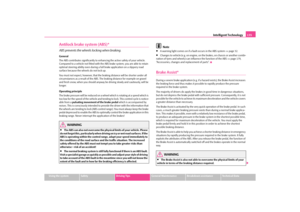 136
136 137
137 138
138 139
139 140
140 141
141 142
142 143
143 144
144 145
145 146
146 147
147 148
148 149
149 150
150 151
151 152
152 153
153 154
154 155
155 156
156 157
157 158
158 159
159 160
160 161
161 162
162 163
163 164
164 165
165 166
166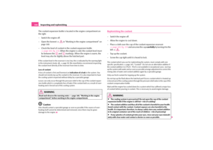 167
167 168
168 169
169 170
170 171
171 172
172 173
173 174
174 175
175 176
176 177
177 178
178 179
179 180
180 181
181 182
182 183
183 184
184 185
185 186
186 187
187 188
188 189
189 190
190 191
191 192
192 193
193 194
194 195
195 196
196 197
197 198
198 199
199 200
200 201
201 202
202 203
203 204
204 205
205 206
206 207
207 208
208 209
209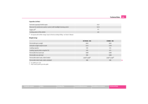 210
210 211
211 212
212 213
213 214
214 215
215 216
216 217
217 218
218 219
219 220
220 221
221 222
222 223
223 Owners Manual Transporting children safely
130
Complete installation instructions are
enclosed with the child safety seat.
WARNING
•
The locking eyes have just been de
veloped for child safety seats which
use")