Page 73 of 95
56A-16
EXTERIOR EQUIPMENT
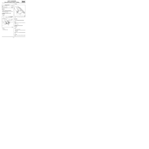
Rear wing extension: Removal - Refitting
C44, and EQUIPMENT LEVEL SPORT
56A
aRemove the protective backing (5) from the double-
sided adhesive tape.
aRefit the bolts (1) , without tightening them.
aCentre the rear wing extender at (3) .
aRefit the side extender of the rear bumper (see 55A,
Exterior protection, Rear bumper: Removal - Re-
fitting, page 55A-10) .
aExert pressure on the bonding areas, moving slowly
and continuously from the centre towards the edges.
aBond the rear wing extender at (6) , (7) ,and (8) .
aTighten the bolts (1) , by applying pressure towards
the vehicle interior.
131785
Note:
To ensure good bonding of the double-sided
adhesive tape, apply continuous pressure using
the palm of the hand against a soft lint-free cloth.
Page 74 of 95

57A-1
INTERIOR EQUIPMENT
Dashboard: Removal - Refitting
57A
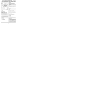
REMOVAL
I - REMOVAL PREPARATION OPERATION
aLock the airbag computer using the Diagnostic tool
(see Fault finding - Replacement of components)
(88C, Airbags and pretensioners).
aDisconnect the battery (see Battery: Removal - Re-
fitting) (80A, Battery).
aRemove the passenger front airbag (see Passen-
ger's frontal airbag: Removal - Refitting) (88C,
Airbags and pretensioners).
aRemove:
-the windscreen pillar trims (see Windscreen pillar
trim: Removal - Refitting) (71A, Body internal
trim),
-the driver's front airbag (see Driver's frontal air-
bag: Removal - Refitting) (88C, Airbags and pre-
tensioners),
-the steering wheel (see Steering wheel: Removal
- Refitting) (36B, Power-assisted steering).aRemove the rev counter (depending on the equip-
ment level) (see Rev counter: Removal - Refitting)
(83A, Instrument panel).
aRemove:
-the steering column switch assembly (see Stee-
ring column switch assembly: Removal - Refit-
ting) (84A, Control - Signals),
-the instrument panel (see Instrument panel: Re-
moval - Refitting) (83A, Instrument panel),
-the tweeters (see Tweeter: Removal - Refitting)
(86A, Radio),
-the centre console (see 57A, Interior equipment,
Centre console: Removal - Refitting, page 57A-
12) ,
-the centre front panel (see 57A, Interior equip-
ment, Centre front panel: Removal - Refitting,
page 57A-7) ,
-the control panel (see Control panel: Removal -
Refitting) (61A, Heating).
aUnclip the dashboard side faces. Equipment required
Diagnostic tool
IMPORTANT
To avoid any risk of triggering when working on or
near a pyrotechnic component (airbags or preten-
sioners), lock the airbag computer using the dia-
gnostic tool.
When this function is activated, all the trigger lines
are inhibited and the airbag warning light on the ins-
trument panel lights up contin uously (ignition on).
IMPORTANT
Never handle the pyrotechnic systems (pretensio-
ners or airbags) near to a source of heat or naked
flame - they may be triggered.
FRONT SIDE AIRBAG
ENGINE REV COUNTER
121136
Page 75 of 95
57A-2
INTERIOR EQUIPMENT
Dashboard: Removal - Refitting
57A
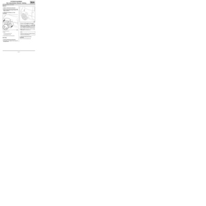
aDisconnect the passenger airbag deactivation con-
nector.
aUnclip:
-the access flap (1) ,
-the diagnostic socket (2) .II - OPERATION FOR REMOVAL OF PART
CONCERNED
aRemove the dashboard bolts (3) .
121135
119521
131791
121159
Page 76 of 95
.
aDetach the various wiring from the dashboard.
aRemove the dashboard")
57A-3
INTERIOR EQUIPMENT
Dashboard: Removal - Refitting
57A
aPartially remove the dashboard (this operation re-
quires two people).
aDetach the various wiring from the dashboard.
aRemove the dashboard (this operation requires two
people).
aNote the route of the cabling.
REFITTING
I - REFITTING PREPARATION OPERATION
aEnsure that the wiring is in good condition.
II - REFITTING OPERATION FOR PART
CONCERNED
aPartially refit the dashboard (this operation requires
two people).
aRefit:
-the various cable harnesses,
-the dashboard (this operation requires two people).
III - FINAL OPERATION.
aClip:
-the diagnostic socket (2) ,
-the access flap (1) .
aConnect the passenger airbag deactivation connec-
tor.
aClip on the dashboard side faces.
aRefit:
-the control panel (see Control panel: Removal -
Refitting) (61A, Heating),
-the instrument panel (see Instrument panel: Re-
moval - Refitting) (83A, Instrument panel),-the tweeters (see Tweeter: Removal - Refitting)
(86A, Radio),
-the centre front panel (see 57A, Interior equip-
ment, Centre front panel: Removal - Refitting,
page 57A-7) ,
-the centre console (see 57A, Interior equipment,
Centre console: Removal - Refitting, page 57A-
12) ,
-the steering column switch assembly (see Stee-
ring column switch assembly: Removal - Refit-
ting) (84A, Control - Signals).
aRefit the rev counter (see Rev counter: Removal -
Refitting) (83A, Instrument panel).
aRefit:
-the steering wheel (see Steering wheel: Removal
- Refitting) (36B, Power-assisted steering),
-the driver's front airbag (see Driver's frontal air-
bag: Removal - Refitting) (88C, Airbags and pre-
tensioners),
-the windscreen pillar trims (see Windscreen pillar
trim: Removal - Refitting) (71A, Body internal
trim).
aRefit the passenger front airbag (see Passenger's
frontal airbag: Removal - Refitting) (88C, Airbags
and pretensioners).
aConnect the battery (see Battery: Removal - Refit-
ting) (80A, Battery).
aCarry out a function test on all functions.
aUnlock the airbag computer using the Diagnostic
tool (see Fault finding - Replacement of compo-
nents) (88C, Airbags and pretensioners).
121157ENGINE REV COUNTER
FRONT SIDE AIRBAG
IMPORTANT
To avoid a fault with or even triggering of pyro-
technic components (airbags or pretensioners),
check the airbag computer using the diagnostic
tool.
Page 77 of 95
57A-4
INTERIOR EQUIPMENT
Dashboard: Conversion
57A
I - DASHBOARD CONVERSION REQUIRED FOR
FITTING AN OFFSET AUDIO SOCKET
1 - Offset audio socket holes
a (X1) = 22 mm.
(X2) = 16 mm.
(X3) = 23 mm.
aDrill the holes using a drill bit (∅ 9 mm).2 - Mounting holes for the offset audio socket unit
a (X4) = 8 mm.
(X5) = 7 mm.
(X6) = 27 mm.
aDrill the holes using a drill bit (∅ 7.5 mm).
II - DASHBOARD CONVERSION REQUIRED FOR
FITTING THE AUDIO CONNECTING BOX (ACB)
1 - Unit wiring hole (ACB)
aHole (7) =∅ 20 mm.
aEnlarge the hole (7) using a conical cutter.
121381
121381
127770
Page 78 of 95
57A-5
INTERIOR EQUIPMENT
Dashboard: Conversion
57A
2 - Unit mounting holes (ACB)
aPosition the unit (ACB) in the glovebox against the
upper edge (8) .
a (X9) = 15 mm
aMark the unit mounting holes.
aDrill the holes using a drill bit (∅ 3 mm).
127771
Note:
Connect the connector before fitting the unit
(ACB).
Page 79 of 95
57A-6
INTERIOR EQUIPMENT
Dashboard side air vent: Removal - Refitting
57A
REFITTING
OPERATION FOR REMOVAL OF PART
CONCERNED
aUnclip the dashboard side air vent at (1) .
REMOVAL
REFITTING OPERATION FOR PART CONCERNED
aClip on the dashboard side air vent back at (1) .
121711
Page 80 of 95
57A-7
INTERIOR EQUIPMENT
Centre front panel: Removal - Refitting
57A
REMOVAL
I - REMOVAL PREPARATION OPERATION
aRemove:
-the radio (see Radio: Removal - Refitting) (MR
411, 86A, Radio),
-the centre console (see 57A, Interior equipment,
Centre console: Removal - Refitting, page 57A-
12) .
aRemove the dashboard lower trim.
aDisconnect the various connectors (1) .II - OPERATION FOR REMOVAL OF PART
CONCERNED
aUnclip the upper section of the centre front panel at
(2) .
aRemove the upper section of the centre front panel.
aRemove:
-the bolts (3) ,
-the clips (4) ,
-the centre front panel.
121142
119711
121141
121161


 from the double-
sided adhesive tape.
aRefit the bolts (1) , wi")
 ,
-the diagnostic socket (2) .II - OPERATION FOR R")
 = 22 mm.
(X2) = 16 mm.
(X3) = 23 mm.
aD")

aPosition the unit (ACB) in the glovebox against the
upper edge (8) .
a (X9) = 15 mm
aMark the unit mounting holes.
aD")
 .
REMOVAL
REFITTING OPERATION FO")
 (MR
411, 86A, Radio),
-the centre co")