Page 145 of 281

35A-5
WHEELS AND TYRES
Wheel: Balancing
35A
aIn some countries, the use of lead weights is forbid-
den; in this case it is recommended to use ZAMAK
weights instead.
Only use weights provided by the Parts Department.
aRemove the wheels (see 35A, Wheels and tyres,
Wheel: Removal - Refitting, page 35A-1) .
aAlways clean the wheel, disc, and hub bearing sur-
faces.
III - PROCEDURE FOR BALANCING THE WHEEL IN
QUESTION
aMake sure that the wheel balancer bearing surface
and all the centring equipment (ring, thrust plate,
etc.) are kept clean.
aTry not to scratch the (alloy) wheel rim with the
wheel tightening device.aThe wheel is fitted on the wheel balancer as follows:
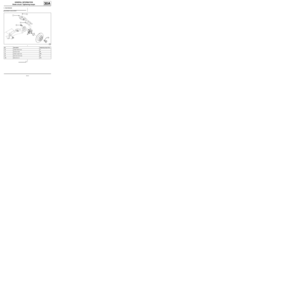
- (5) ring,
- (6) wheel balancer back-plate,
- (7) wheel tightening device (certain alloy wheels
require a device 200 mm in diameter to ensure that
the wheel has been correctly tightened),
- (8) outer wheel plane,
- (9) wheel.
aPlace the wheel on the wheel balancer, with the
valve at the top, then lock the wheel in place.
aRemove any stones trapped in the tyre tread.
113742
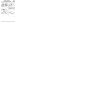
(2) Steel wheel with flange
(3) Alloy wheel with flange
(4) Alloy wheel without flange
105871
100681
Page 146 of 281
35A-6
WHEELS AND TYRES
Wheel: Balancing
35A
aEnter the specific wheel parameters when starting
the wheel balancer.
aStart the wheel balancer and check the wheel bal-
ance, which should be 0 g on each plane of the
wheel.
aIf this is not the case, remove the old wheel balanc-
ing weights and repeat the wheel balancing proce-
dure, checking that the wheel balance equals 0 on
each wheel plane.
IV - FINAL OPERATION
aRefit the wheel (see 35A, Wheels and tyres,
Wheel: Removal - Refitting, page 35A-1) . WARNING
To avoid detachment of the balance weights, use
only weights which correspond to the vehicle
wheel rims.
Page 147 of 281
35A-7
WHEELS AND TYRES
Tyres: Identification
35A
Example of a tyre identification mark: 205/65 R 15 91
V.Speed code table:
101008
123448
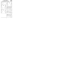
205 Tyre width in mm (L)
65 Height/width ratio
RRadial structure
15 Internal diameter in inches (c)
91 Load index
VSpeed code
Code Maximum
speed in
mph (km/h)
R170
S180
T190
U200
H210
V240
ZR above 240
W270
Y300
Page 148 of 281

35A-8
WHEELS AND TYRES
Tyres: Removal - Refitting
35A
REMOVAL
I - REMOVAL PREPARATION OPERATION
aPosition the vehicle on a two-post lift (see Vehicle:
Towing and lifting) (02A, Lifting equipment).
aRemove:
-the wheel in question (see 35A, Wheels and tyres,
Wheel: Removal - Refitting, page 35A-1) ,
-the balance weights,
-the valve mechanism.
II - OPERATION FOR REMOVAL OF PART
CONCERNED
aDetach:
-the bead from the outside of the tyre, starting with
the side opposite the valve,
-the bead from the inside of the tyre.aPosition the tyre lever approximately 15 cm from the
valve on the outside of the wheel rim in order to re-
move the exterior bead from the tyre.
aRemove the exterior bead of the tyre, finishing at the
valve.
aPosition the tyre lever approximately 15 cm from the
valve on the outside of the wheel rim in order to re-
move the bead from inside the tyre.
aRemove the interior bead of the tyre, finishing at the
valve.
REFITTING
I - REFITTING PREPARATION OPERATION
aparts always to be replaced: Tyre valve
aLubricate the two tyre beads correctly using the
TYRE PASTE (see Vehicle: Parts and consum-
ables for the repair) (04B, Consumables - Prod-
ucts).
II - REFITTING OPERATION FOR PART
CONCERNED
aEngage the lower tyre bead approximately 15 cm af-
ter the valve.
aFinish fitting the tyre at the valve.
aFit the exterior bead approximately 15 cm after the
valve using the tyre lever.
aInflate the tyre to 3.5 bar to press the tyre beads
against the wheel rim.
18884
18885
Page 149 of 281
35A-9
WHEELS AND TYRES
Tyres: Removal - Refitting
35A
III - FINAL OPERATION
aRefit the valve mechanism.
aInflate the tyre to the recommended pressure (see
35A, Wheels and tyres, Tyre pressure: Identifica-
tion, page 35A-10) .
aBalance the wheel (see 35A, Wheels and tyres,
Wheel: Balancing, page 35A-4) .
aRefit the wheel in question (see 35A, Wheels and
tyres, Wheel: Removal - Refitting, page 35A-1) . Note:
It is not necessary to drive the vehicle before and
after a new wheel is balanced.
Page 150 of 281
35A-10
WHEELS AND TYRES
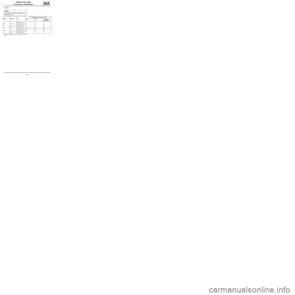
Tyre pressure: Identification
35A
INFLATION
The pressure values given are « motorway » pres-
sures.WARNING
If checking the pressure when hot, increase the tyre
inflation pressure by 0.2 to 0.3 bar above the rec-
ommended pressure.
Engine Wheel rim TyreTyre inflation pressure when cold (bar)
Front Rear emergency
spare wheel
D4F
D7F5.5 J 14165/65 R14 79T
2.2 2.0 2.2 175/65 R14 82 T
6 J 15 185/55 R15 82H
K9K5.5 J 14165/65 R14 79T 2.3 2.1 2.3
175/65 R14 82 T
2.2 2.0 2.2
6 J 15 185/55 R15 82H
Page 151 of 281

35A-11
WHEELS AND TYRES
Wheel rim: Identification
35A
IDENTIFICATION
1 - Marking
There are two types of identification marking on the
wheel rims:
-engraved marking for steel wheel rims,
-cast marking for alloy wheel rims.
The marking gives the main dimensional specifications
of the wheel rim.
This marking may be:
-complete, for example 6 J 15 5 CH 36,
-simplified, for example 6 J 15.
There are 3 types of wheel rim edges (2) :
-those with two flat edges,
-those with two raised edges,
-those with one flat edge and one raised edge.2 - Installation diameter for the wheel bolts
The wheel bolts are positioned with a pitch circle dia-
meter of:
-5 holes: 108 mm,
-4 holes: 100 mm.
3 - Rim run-out
The maximum run-out is measured at the wheel rim
edge (7) .
Steel wheel rims: 0.8 mm
Alloy wheel rims: 0.3 mm
4 - Out-of-roundness
The maximum out-of-round value is measured on the
tyre bead bearing surface.
0.7 mm Wheel type 6 J 15
1Width (in inches) 6
2Rim edge profile J
3Nominal diameter (in inches) 15
4Number of holes 5
5Anchorage profile of the tyre CH
6Offset (in mm) 36
100988
Page 152 of 281

36A-1
STEERING ASSEMBLY
Steering box: Removal - Refitting
36A
REMOVAL
I - REMOVAL PREPARATION OPERATION
aPosition the vehicle on a two-post lift ( (see Vehicle:
Towing and lifting) ).
aRemove:
-the front wheels (see 35A, Wheels and tyres,
Wheel: Removal - Refitting, page 35A-1) ,
-the front wheel arch liners (see Front wheel arch
liner: Removal - Refitting) (55A, Exterior protec-
tion),
-the « subframe - front driveshaft lower arm - power-
assisted steering box - front anti-roll bar » assem-
bly (see 31A, Front axle components, Front axle
subframe: Removal - Refitting, page 31A-43) .
II - OPERATION FOR REMOVAL OF PART
CONCERNED
aRemove:
-the power-assisted steering box bolts (1) ,
-the power-assisted steering box.
REFITTING
I - REFITTING OPERATION FOR PART
CONCERNED
aRefit:
-the power-assisted steering box,
-the power-assisted steering box bolts.
aTorque tighten the power-assisted steering box
bolts (105 Nm).
II - FINAL OPERATION.
aRefit:
-the « subframe - front driveshaft lower arm - power-
assisted steering box - front anti-roll bar » assem-
bly (see 31A, Front axle components, Front axle
subframe: Removal - Refitting, page 31A-43) ,
-the wheel arch liners (see Front wheel arch liner:
Removal - Refitting) (55A, Exterior protection),
-the front wheels (see 35A, Wheels and tyres,
Wheel: Removal - Refitting, page 35A-1) .
aCheck the axle geometry (see 30A, General infor-
mation, Axle assemblies: Check, page 30A-23) .
aIf necessary, adjust the axle assemblies' geometry
(see 30A, General information, Front axle sys-
tem: Adjustment, page 30A-36) . Tightening torquesm
power-assisted steering
box bolts105 Nm
119405