Page 225 of 281

37A-46
MECHANICAL COMPONENT CONTROLS
Parking brake lever: Removal - Refitting
37A
REMOVAL
I - REMOVAL PREPARATION OPERATION
aPosition the vehicle on a two-post lift (see Vehicle:
Towing and lifting) (MR 411, 02A, Lifting equip-
ment).
aRelease the parking brake lever.
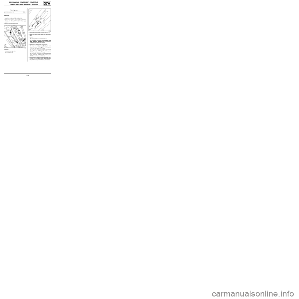
aRemove:
-the heat shield clips (1) ,
-the heat shield (2) .aRemove the parking brake lever adjusting nut (3) .
aDetach the parking brake cables from the compen-
sator.
aRemove:
-the parking brake lever compensator (4) ,
-the front seats, completely (see Complete front
seat: Removal - Refitting) (MR 412 Bodywork,
75A, Front seat frames and runners).
aDepending on the equipment level, remove:
-the rear bench seatback (see Rear bench seat-
back: Removal - Refitting) (MR 412 Bodywork,
76A, Rear seat frames and runners),
-the rear bench seat base (see Rear bench seat
base: Removal - Refitting) (MR 412 Bodywork,
76A, Rear seat frames and runners)
-the rear seats, completely (see Complete rear
seat: Removal - Refitting) (MR 412 Bodywork,
76A, Rear seat frames and runners).
aPartially remove the floor carpet to access the park-
ing brake lever (see Floor carpet: Removal - Refit-
ting) (MR 412 Bodywork, 71A, Body internal trim). Tightening torquesm
par king brake lever nuts8 Nm
121325
121334
Page 226 of 281

37A-47
MECHANICAL COMPONENT CONTROLS
Parking brake lever: Removal - Refitting
37A
II - OPERATION FOR REMOVAL OF PART
CONCERNED
aRemove:
-the nuts (6) from the parking brake lever,
-the parking brake lever (7) .
REFITTING
I - REFITTING OPERATION FOR PART
CONCERNED
aRefit:
-the parking brake lever,
-the parking brake lever nuts.
aTorque tighten the parking brake lever nuts (8
Nm).
II - FINAL OPERATION.
aFit the floor carpet (see Floor carpet: Removal -
Refitting) (MR 412 Bodywork, 71A, Body internal
trim).
aRefit (depending on equipment level):
-the rear seats, completely (see Complete rear
seat: Removal - Refitting) (MR 412 Bodywork,
76A, Rear seat frames and runners),
-the rear bench seat base (see Rear bench seat
base: Removal - Refitting) (MR 412 Bodywork,
76A, Rear seat frames and runners),-the rear bench seatback (see Rear bench seat-
back: Removal - Refitting) (MR 412 Bodywork,
76A, Rear seat frames and runners).
aRefit the front seats, completely (see Complete
front seat: Removal - Refitting) (MR 412 Body-
work, 75A, Front seat frames and runners).
aAttach the parking brake cables to the compensator.
aRefit the parking brake lever adjusting nut.
aAdjust the parking brake lever (see 37A, Mechani-
cal component controls, Parking brake lever:
Adjustment, page 37A-48) .
aRefit:
-the heat shield,
-the heat shield clips.
121607
Page 227 of 281

37A-48
MECHANICAL COMPONENT CONTROLS
Parking brake lever: Adjustment
37A
A poorly adjusted parking brake:
-prevents correct operation of the automatic compen-
sation system for the brake shoes,
-causes premature wear of brake shoes.
ADJUSTMENT
I - ADJUSTMENT PREPARATION OPERATION
aPosition the vehicle on a two-post lift (see Vehicle:
Towing and lifting) .
aApply the parking brake five times to condition the
cables for normal use.
aPut the parking brake lever into the released posi-
tion.
aCheck that the rear wheels turn freely. If they do not,
check the following components and if necessary re-
pair:
-the parking brake cables,
-the calliper piston,
-the automatic compensation system,
-calliper
aRemove the rear wheels (see 35A, Wheels and ty-
res, Wheel: Removal - Refitting, page 35A-1) .
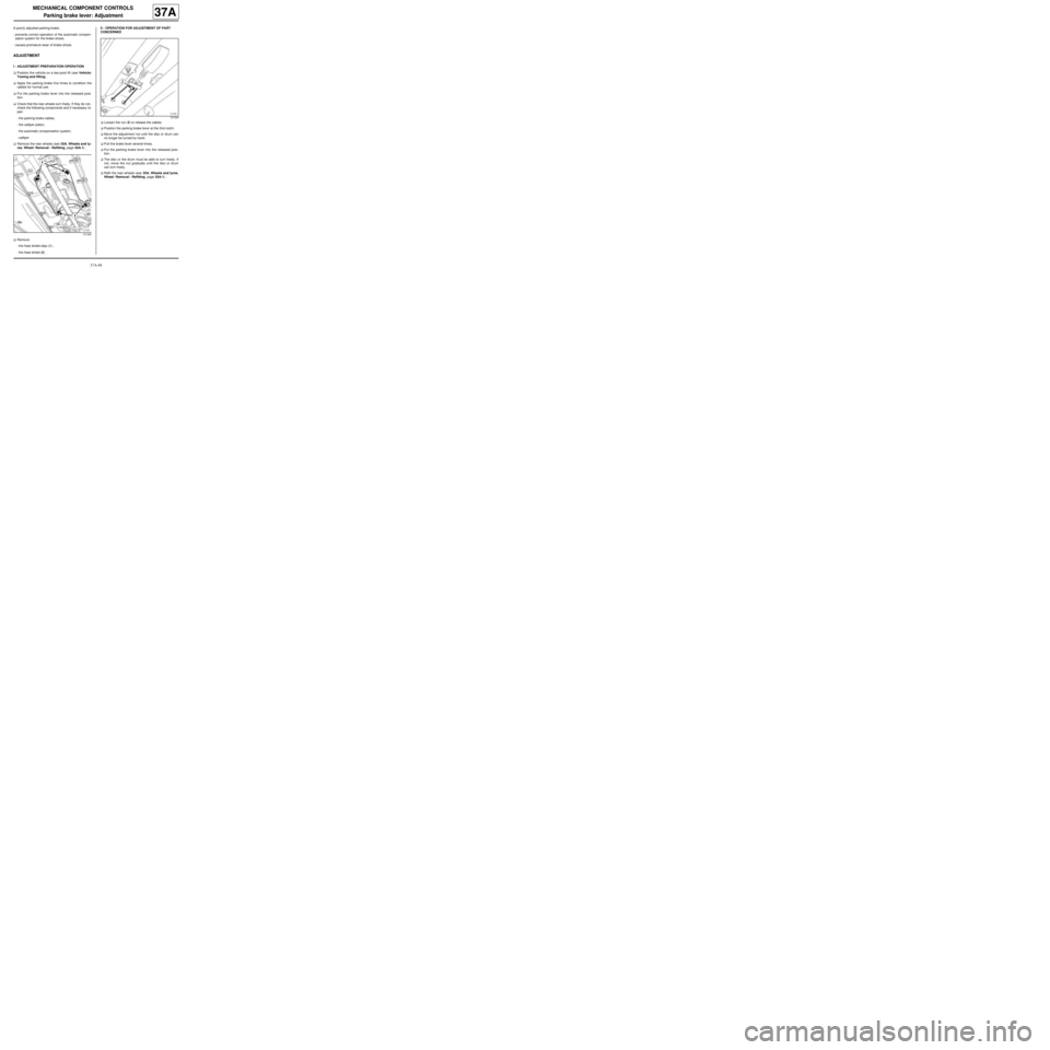
aRemove:
-the heat shield clips (1) ,
-the heat shield (2) .II - OPERATION FOR ADJUSTMENT OF PART
CONCERNED
aLoosen the nut (2) to release the cables.
aPosition the parking brake lever at the 2nd notch.
aMove the adjustment nut until the disc or drum can
no longer be turned by hand.
aPull the brake lever several times.
aPut the parking brake lever into the released posi-
tion.
aThe disc or the drum must be able to turn freely. If
not, move the nut gradually until the disc or drum
can turn freely.
aRefit the rear wheels (see 35A, Wheels and tyres,
Wheel: Removal - Refitting, page 35A-1) .
121325
121334
Page 228 of 281
37A-49
MECHANICAL COMPONENT CONTROLS
Clutch control: List and location of components
JB1
37A
No. Description
(1) Clutch fork
(2) Clutch control cable
(3) Brake - clutch pedal
121113
Page 229 of 281
37A-50
MECHANICAL COMPONENT CONTROLS
Clutch control: List and location of components
JH3
37A
No. Description
(1) Clutch slave cylinder (clutch thr ust bearing)
(2) Hydraulic clutch control pipes
(3) Filter
(4) Clutch master cylinder
(5) Brake fluid supply duct
(6) Brake fluid reservoir
(7) Clutch pedal
121114
Page 230 of 281

37A-51
MECHANICAL COMPONENT CONTROLS
Clutch cable: Removal - Refitting
JB1
37A
REMOVAL
I - REMOVAL PREPARATION OPERATION
aRemove:
-the battery (see Battery: Removal - Refitting)
(MR 411, 80A, Battery),
-the battery tray (see Battery tray: Removal - Re-
fitting) (MR 411, 80A, Battery),
-the « brake pedal - clutch » assembly (see ) .
II - OPERATION FOR REMOVAL OF PART
CONCERNED
aUnclip the cable sleeve stop (1) from the bulkhead
and remove the passenger compartment cable.
aDetach the clutch cable at (2) .
aDetach the cable sleeve stop (3) from the fork on the
gearbox.
aDetach the clutch cable from the clutch fork at (4) .
aRemove the clutch cable.
REFITTING
I - REFITTING OPERATION FOR PART
CONCERNED
aRefit the clutch cable.
aAttach the clutch cable to the clutch fork.
aFit the cable sleeve stop to the fork on the gearbox.
aAttach the clutch cable.
aFit the clutch cable through the opening in the bulk-
head and clip on the cable sleeve stop.II - FINAL OPERATION.
aRefit:
-the « brake pedal - clutch » assembly (see ) ,
-the battery tray (see Battery tray: Removal - Re-
fitting) (MR 411, 80A, Battery),
-the battery (see Battery: Removal - Refitting)
(MR 411, 80A, Battery).
121113
Page 231 of 281
37A-52
MECHANICAL COMPONENT CONTROLS
Clutch pedal switch: Removal - Refitting
CRUISE CONTROL, and 5-SPEED MANUAL GEARBOX
37A
REMOVAL
I - REMOVAL PREPARATION OPERATION
aRemove the dashboard glovebox.
aDisconnect the connector (2) from the clutch pedal
switch.II - OPERATION FOR REMOVAL OF PART
CONCERNED
aTurn the clutch pedal switch (3) a quarter of a turn
anti-clockwise
aRemove the clutch pedal switch from the pedal. Equipment required
Diagnostic tool
119506
119507
121349
Page 232 of 281

37A-53
MECHANICAL COMPONENT CONTROLS
Clutch pedal switch: Removal - Refitting
CRUISE CONTROL, and 5-SPEED MANUAL GEARBOX
37A
REFITTING
I - REFITTING PREPARATIONS OPERATION
a
aMeasure dimension of the piston (4) . If the dimen-
sion (x) is less than 15 mm, carefully pull the end of
the piston (4) to adjust the dimension to between 15
mm minimum and 17 mm maximum.
II - REFITTING OPERATION FOR PART
CONCERNED
aDepress the clutch pedal by hand.
aFit the clutch pedal switch to the pedal.
aLock the clutch pedal switch by turning it a quarter of
a turn clockwise.
aAt the same time, carefully return the clutch pedal.
III - FINAL OPERATION.
aConnect the clutch pedal switch connector.aBe sure to carry out a repair check using Diagnostic
tool.
aRefit the dashboard glovebox.
108436
WARNING
Whenever the clutch pedal switch piston is com-
pletely removed, the switch must be replaced.
WARNING
The switch must be replaced if handling of the
piston results in three adjustments being made.
Note:
The clutch pedal switch has an automatic adjust-
ment feature, adapting to the pedal position.
The automatic adjustment makes a clicking noise
when in operation.