Page 89 of 281
31A-46
FRONT AXLE COMPONENTS
Front axle subframe: Removal - Refitting
31A
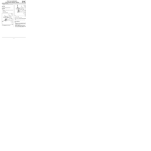
-the subframe tie-rod bolts (10) ,
-the subframe tie-rods.
aRemove:
-the rear suspended engine mounting (11) (see
Lower engine tie-bar: Removal - Refitting) (19D,
Engine mounting),
-the acoustic tie-rod bolts (12) ,
-the acoustic tie rods.
aPosition the (Mot. 1390).
aRemove the left-hand tie-rod bolt (13) .aAttach the cooling radiator to the upper cross mem-
ber.
aRemove:
-the bolts (14) from the front end cross member,
-the subframe bolts (15) ,
-the « subframe - front driveshaft lower arm - steer-
ing box - front anti-roll bar » assembly with the
(Mot. 1390).
119335
132029
119336
Note:
This operation requires two people.
Page 90 of 281
31A-47
FRONT AXLE COMPONENTS
Front axle subframe: Removal - Refitting
31A
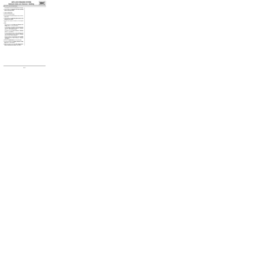
aRemove:
-the steering box (16) (see 36A, Steering assem-
bly, Steering box: Removal - Refitting, page
36A-1) ,
-the front anti-roll bar (17) (see 31A, Front axle
components, Front anti-roll bar: Removal - Re-
fitting, page 31A-52) ,
-the lower arms from the front driveshaft (18) (see
31A, Front axle components, Front driveshaft
lower arm: Removal - Refitting, page 31A-33) .aRemove:
-the gear selection cable guide bolt (19) from the
subframe,
-the gear selection cable guide (19) from the sub-
frame.
REFITTING
I - REFITTING PREPARATION OPERATION
aAlways replace:
-the subframe bolts,
-the bolt from the universal joint.
aDegrease the contact surface areas of the subframe
and the body using surface cleaner (see Vehicle:
Parts and consumables for the repair) (04B, Con-
sumables - Products).
119429
K9K
124348
Page 91 of 281

31A-48
FRONT AXLE COMPONENTS
Front axle subframe: Removal - Refitting
31A
II - REFITTING OPERATION FOR PART
CONCERNED
aRefit the speed selection cable guide on the sub-
frame.
aRefit:
-the front driveshaft lower arms (see 31A, Front
axle components, Front driveshaft lower arm:
Removal - Refitting, page 31A-33) ,
-the front anti-roll bar (see 31A, Front axle compo-
nents, Front anti-roll bar: Removal - Refitting,
page 31A-52) ,
-the steering box (see 36A, Steering assembly,
Steering box: Removal - Refitting, page 36A-1) .
aRefit the « subframe - front driveshaft lower arm -
steering box - front anti-roll bar » assembly with the
(Mot. 1390).
aTighten to torque:
-the rear subframe bolts (105 Nm) (20) ,
-the front subframe bolts (62 Nm) (22) ,
-the front end cross member bolts (21 Nm) (21) .aRefit:
-the rear suspended engine mounting (see Lower
engine tie-bar: Removal - Refitting) (19D, En-
gine mounting),
-the acoustic tie rods.
aTighten to torque:
-the acoustic tie-rod bolts (21 Nm) (23) ,
-the acoustic tie-rod bolts (90 Nm) (24) .
aRefit the sub-frame tie-rods.
aTighten to torque:
-the subframe tie-rod bolts (21 Nm),
-the subframe tie-rod nuts (62 Nm).
aCheck the position of the gear selection cables in the
guide.
aFit the gearbox control gear lever arm.
aTorque tighten the gear lever arm nut (28 Nm).
aFit the gear lever arm rubber protector. K9K
Note:
Be careful with the guide of the lower or upper
radiator when fitting the subframe. There is a risk
of the radiator guides breaking.
119336
119335
K9K
JB1
Page 92 of 281

31A-49
FRONT AXLE COMPONENTS
Front axle subframe: Removal - Refitting
31A
aCheck that the bush (25) is correctly positioned on
the lower arm ball joint.
aRefit:
-the lower arm ball joints,
-the track rod ends.
aRefit the anti-roll bar tie-rods to the shock absorbers.
aTorque tighten the nuts of the lower arm ball
joints (62 N.m).
aTorque tighten the bolts of the lower ball joints (62
N.m).
aTorque tighten the nuts of the track rod ends (37
N.m).
aObserve the direction of fitting for the universal joint
cam nut and bolt.
afit the universal joint to the steering box.aRefit the universal joint cam nut and a new bolt.
aPosition the universal joint cam nut and bolt.
aImmobilise the cam nut in its housing (on the univer-
sal joint).
aPretighten the universal joint cam nut and bolt.
aCheck that the universal joint is in the correct posi-
tion.
aTorque tighten the universal joint bolt (24 Nm).
aRemove the flywheel immobiliser.
III - FINAL OPERATION.
aRefit:
-the front wheel arch liners (see Front wheel arch
liner: Removal - Refitting) (55A, Exterior protec-
tion),
119223
EQ UIPMENT LEVEL SPORT
EQUIPMENT LEVEL EA0 or EQUIPMENT LEVEL
EA1 or EQUIPMENT LEVEL EA3 or EQUIPMENT
LEVEL EA5 or EQUIPMENT LEVEL EAG
116021
116022
Page 93 of 281
31A-50
FRONT AXLE COMPONENTS
Front axle subframe: Removal - Refitting
31A
-the front wheels (see 35A, Wheels and tyres,
Wheel: Removal - Refitting, page 35A-1) .
aCheck the front axle geometry (see 30A, General
information, Front axle assembly: Adjustment
values, page 30A-31) .
Page 94 of 281
31A-51
FRONT AXLE COMPONENTS
Radiator mounting cross member: Removal - Refitting31A
REMOVAL
I - REMOVAL PREPARATION OPERATION
aRemove the front bumper ( (see Front bumper: Re-
moval - Refitting) ).
aAttach the radiator upper section.
II - OPERATION FOR REMOVAL OF PART
CONCERNED
aRemove:
-the bolts (1) ,
-the radiator mounting cross member.
REFITTING
I - REFITTING OPERATION FOR PART
CONCERNED
aRefit:
-the radiator mounting cross member,
-the bolts (1) .
aTorque tighten the radiator mounting cross mem-
ber bolts (44 Nm).II - FINAL OPERATION.
aDetach the radiator upper section.
aRefit the front bumper ( (see Front bumper: Re-
moval - Refitting) ). Tightening torquesm
radiator mounting cross
member bolts44 Nm
121040
Page 95 of 281

31A-52
FRONT AXLE COMPONENTS
Front anti-roll bar: Removal - Refitting
EQ UIPMENT LEVEL EA0 or EQUIPMENT LEVEL EA1 or EQUIPMENT LEVEL EA3 or EQUIPMENT LEVEL EA5
or EQUIPMENT LEVEL EAG or EQUIPMENT LEVEL EZ2 or EQUIPMENT LEVEL EZ4
31A
Anti-roll bar specifications:
REMOVAL
I - REMOVAL PREPARATION OPERATION
aPosition the vehicle on a two-post lift (see Vehicle:
Towing and lifting) (02A, Lifting equipment).
aRemove the front axle subframe (see 31A, Front
axle components, Front axle subframe: Removal
- Refitting, page 31A-43) .II - OPERATION FOR REMOVAL OF PART
CONCERNED
aCompress the anti-roll bar rubber mounting bush on
the wheel side using the (Sus. 1413).
aRemove:
-the bolt (1) from the anti-roll bar on the wheel side,
-the rubber mounting bush from the anti-roll bar,
-the anti-roll bar bearing bolts (2) ,
-the anti-roll bar bearings,
-the anti-roll bar,
-the rubber mounting bush from the anti-roll bar
bearing.
REFITTING
REFITTING OPERATION FOR PART CONCERNED
aRefit:
-the anti-roll bar bearing rubber mounting bush,
-the anti-roll bar.
aFit the anti-roll bar bearings into the subframe neck. Special tooling required
Sus. 1413Rubber mounting compres-
sor for fitting the anti-roll bar.
(wheel end).
Sus. 1824Fork for fitting the anti-roll bar
centre bearings.
Tightening torquesm
anti-roll bar bearing
bolts on the subframe35 Nm
anti-roll bar bolt on the
wheel side14 Nm
Engine Ø of the strut in
mm
D7F 25
D4F, K9K 26
119406
Page 96 of 281
31A-53
FRONT AXLE COMPONENTS
Front anti-roll bar: Removal - Refitting
EQ UIPMENT LEVEL EA0 or EQUIPMENT LEVEL EA1 or EQUIPMENT LEVEL EA3 or EQUIPMENT LEVEL EA5
or EQUIPMENT LEVEL EAG or EQUIPMENT LEVEL EZ2 or EQUIPMENT LEVEL EZ4
31A
aFit the (Sus. 1824) (3) on the anti-roll bar.
aLift the (Sus. 1824).
aRefit the anti-roll bar bearing bolts (4) .
aTorque tighten the anti-roll bar bearing bolts on
the subframe (35 Nm).
aRefit:
-the anti-roll bar rubber mounting bush on the wheel
side,
-the anti-roll bar bolt on the wheel side.aRefit the front axle subframe (see 31A, Front axle
components, Front axle subframe: Removal -
Refitting, page 31A-43) .
aCompress the anti-roll bar rubber mounting bush on
the wheel side using the (Sus. 1413) (5) .
aRefit the anti-roll bar nut (6) on the wheel side.
aTorque tighten the anti-roll bar bolt on the wheel
side ( 14 Nm).
119403
119404
12992