Page 3025 of 4331
EM-78< ON-VEHICLE REPAIR >
[HR16DE]
OIL SEAL
Use Genuine Silicone RTV Seal ant or equivalent. Refer to GI-42, " Recommended Chemical Prod-
uct and Sealant " .
2. Install rear oil seal so that each seal lip is oriented as shown.
• Press-fit rear oil seal with a drift (a) outer diameter 113 mm(4.45 in) and inner diameter 90 mm (3.54 in).
CAUTION:
• Be careful not to damage crankshaft and cylinder block.
• Press-fit oil seal straight to avoid causing burrs or tilt-
ing.
• Never touch grease applied onto oil seal lip.
• Press in rear oil seal (1) to the position as shown.
3. After press-fitting rear oil seal, completely wipe off any liquid gasket protruding to rear end surface side.
4. Installation of the remaining components is in the reverse order of removal. A : Dust seal lip
B : Oil seal lip
: Engine outside
: Engine inside PBIC3485J
PBIC3660E
A : Rear end surface of cylinder block
PBIC3761E
Page 3027 of 4331
Cylinder
Block " .
1. Wipe off engine oil and remove water scale (like deposit ), gasket, sealant, carbon, etc. with a scraper.
CAUTION:
Never allow gasket debris to enter passag es for engine oil or engine coolant.
2. At each of several locations on bottom surface of cylinder head, measure the distortion in six directions.
• If it exceeds the limit, replace cylinder head.
INSTALLATION
1. Install new cylinder head gasket. A : EXH side
B : INT side
: Engine front Cylinder Head " .
Page 3028 of 4331
![NISSAN TIIDA 2009 Service Repair Manual CYLINDER HEAD
EM-81
< ON-VEHICLE REPAIR >
[HR16DE] C
D E
F
G H
I
J
K L
M A EM
NP
O
2. Tighten cylinder head bolts in numer
ical order as shown with the
following procedure to install cylinder head.
CA NISSAN TIIDA 2009 Service Repair Manual CYLINDER HEAD
EM-81
< ON-VEHICLE REPAIR >
[HR16DE] C
D E
F
G H
I
J
K L
M A EM
NP
O
2. Tighten cylinder head bolts in numer
ical order as shown with the
following procedure to install cylinder head.
CA](/manual-img/5/57398/w960_57398-3027.png)
CYLINDER HEAD
EM-81
< ON-VEHICLE REPAIR >
[HR16DE] C
D E
F
G H
I
J
K L
M A EM
NP
O
2. Tighten cylinder head bolts in numer
ical order as shown with the
following procedure to install cylinder head.
CAUTION:
If cylinder head bolts are re -used, check their outer diame-
ters before installation. Fol low the “Cylinder Head Bolts
Outer Diameter” measurement procedure.
a. Apply new engine oil to threads and seating surfaces of bolts.
b. Tighten all bolts in the specified order.
c. Turn all bolts 60 degrees clockwise (angle tightening) using Tool (A) in the specified order.
CAUTION:
Check and confirm the tightening angle by using Tool (A) or
protractor. Avoid judgment by visual inspection without the
tool.
d. Completely loosen all bolts in reverse order. CAUTION:
In this step, loosen bolts in reverse order of that indicated.
e. Tighten all bolts in the specified order.
f. Turn all bolts 75 degrees clockwise (angle tightening) using Tool (A) in the specified order.
CAUTION:
Check and confirm the tightening angle by using Tool (A) or
protractor. Avoid judgment by visual inspection without the
tool.
g. Turn all bolts 75 degrees clockwise again (angle tightening) using Tool (A) in the specified order.
CAUTION:
Check and confirm the tightening angle by using To ol (A) or protractor. Avoid judgment by visual
inspection without the tool.
3. Installation of the remaining components is in the reverse order of removal.
INSPECTION AFTER INSTALLATION
Inspection for Leaks • Before starting engine, check oil/fluid levels incl uding engine coolant and engine oil. If less than required
quantity, fill to the specified level. Refer to MA-14, " Fluids and Lubricants " .
A : EXH side
B : INT side
: Engine front
: 40.0 N·m (4.1 kg-m, 30 ft-lb)
Tool number : KV10112100 (BT-8653-A) PBIC3732E
PBIC3733E
: 0 N·m (0 kg-m, 0 ft-lb)
: 40.0 N·m (4.1 kg-m, 30 ft-lb)
Tool number : KV10112100 (BT-8653-A) PBIC3733E
Page 3042 of 4331
EM
NP
O
CYLINDER BLOCK
Exploded View INFOID:0000000004784316
1. Crankshaft position sensor (POS) cover 2. Crankshaft position sensor (POS) 3. O-ring
4. Water drain plug 5. Cylinder block 6. Oil level gauge
7. Oil level gauge guide 8. O-ring 9. Knock sensor
Page 3044 of 4331

EM
NP
O
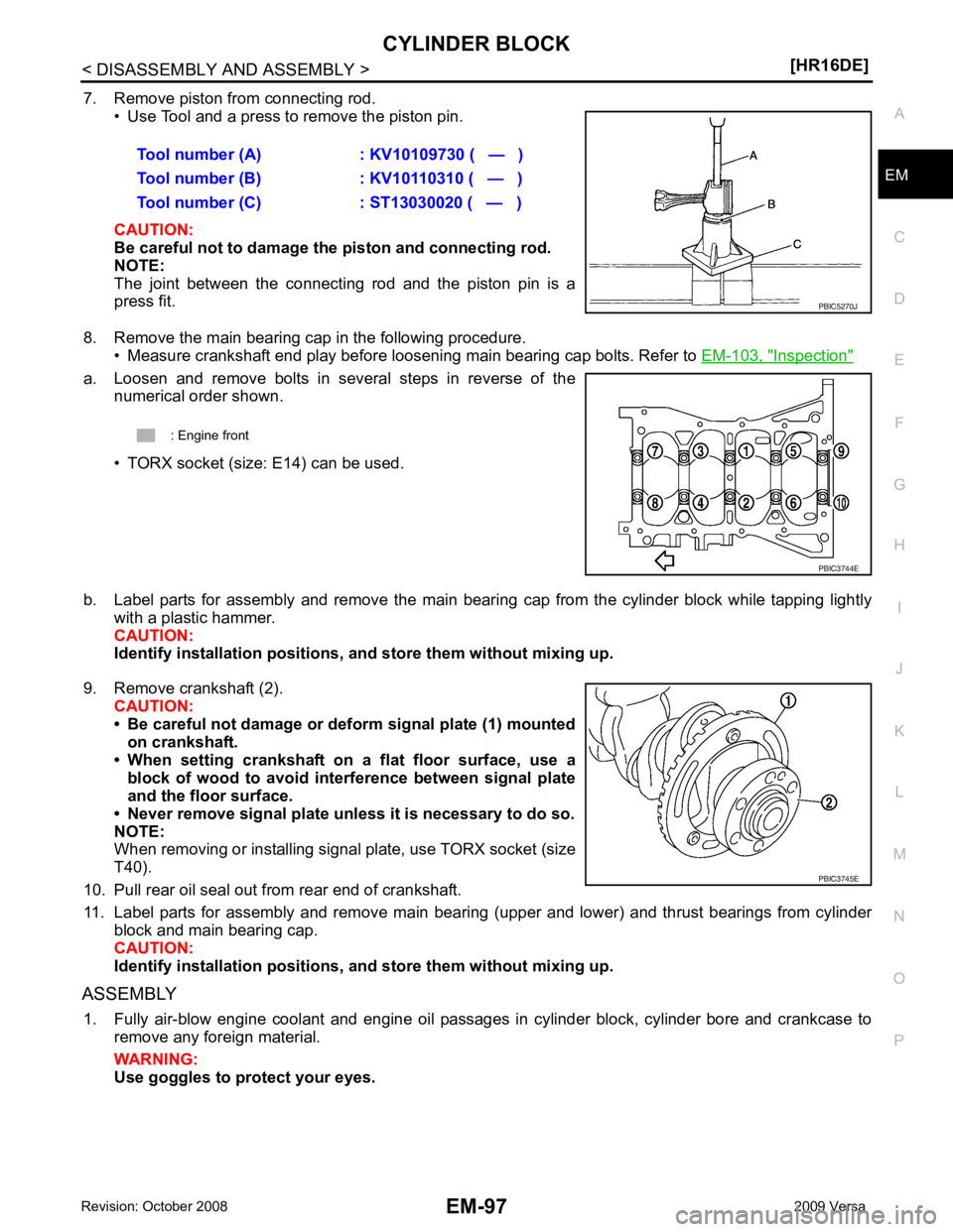
7. Remove piston from connecting rod.
• Use Tool and a press to remove the piston pin.
CAUTION:
Be careful not to damage the piston and connecting rod.
NOTE:
The joint between the connecting rod and the piston pin is a
press fit.
8. Remove the main bearing cap in the following procedure. • Measure crankshaft end play before loosening main bearing cap bolts. Refer to EM-103, " Inspection "
a. Loosen and remove bolts in several steps in reverse of the
numerical order shown.
• TORX socket (size: E14) can be used.
b. Label parts for assembly and remove the main beari ng cap from the cylinder block while tapping lightly
with a plastic hammer.
CAUTION:
Identify installation positions, and store th em without mixing up.
9. Remove crankshaft (2). CAUTION:
• Be careful not damage or deform signal plate (1) mounted on crankshaft.
• When setting crankshaft on a flat floor surface, use a
block of wood to avoid inte rference between signal plate
and the floor surface.
• Never remove signal plate unl ess it is necessary to do so.
NOTE:
When removing or installing signal plate, use TORX socket (size
T40).
10. Pull rear oil seal out from rear end of crankshaft.
11. Label parts for assembly and remove main bearing (upper and lower) and thrust bearings from cylinder block and main bearing cap.
CAUTION:
Identify installation positions, and store th em without mixing up.
ASSEMBLY 1. Fully air-blow engine coolant and engine oil passages in cylinder block, cylinder bore and crankcase to remove any foreign material.
WARNING:
Use goggles to protect your eyes. Tool number (A) : KV10109730 ( — )
Tool number (B) : KV10110310 ( — )
Tool number (C) : ST13030020 ( — )
Page 3045 of 4331
![NISSAN TIIDA 2009 Service Repair Manual EM-98< DISASSEMBLY AND ASSEMBLY >
[HR16DE]
CYLINDER BLOCK
2. Install water drain plug (1) to cylinder block as shown.
Use Genuine Silicone RTV Seal ant or equivalent. Refer to
GI-42, " Recomm NISSAN TIIDA 2009 Service Repair Manual EM-98< DISASSEMBLY AND ASSEMBLY >
[HR16DE]
CYLINDER BLOCK
2. Install water drain plug (1) to cylinder block as shown.
Use Genuine Silicone RTV Seal ant or equivalent. Refer to
GI-42, " Recomm](/manual-img/5/57398/w960_57398-3044.png)
EM-98< DISASSEMBLY AND ASSEMBLY >
[HR16DE]
CYLINDER BLOCK
2. Install water drain plug (1) to cylinder block as shown.
Use Genuine Silicone RTV Seal ant or equivalent. Refer to
GI-42, " Recommended Chemical
Product and Sealant " .
3. Install main bearings and thrust bearings in their original positions with the following procedure:
a. Remove dust, dirt, and engine oil on the bearing mating surfaces of cylinder block.
b. Install thrust bearings to the both sides of the No. 3 journal hous- ing (B) on cylinder block.
• Install thrust bearings with the oil groove (A) facing crankshaft arm (outside).
c. Install the main bearings (1) paying attention to the direction. • Install the one with oil holes (A) onto cylinder block and the
one without oil holes onto main bearing cap.
• Before installing main bearings, apply new engine oil to the bearing surface (inside). Do not apply engine oil to the back
surface, but thoroughly clean it.
• Ensure the oil holes on cylinder block and those on the corre- sponding bearing are aligned.
• Install the main bearing in the position shown.
NOTE:
Install the main bearing in the center position with the following
dimension. For service operati on, the center position can be
checked visually. : Engine front PBIC3742E
: Engine front
PBIC3258J
PBIC3746E
1 : Cylinder block
2 : Main bearing (upper)
3 : Main bearing (lower)
4 : Main bearing cap
: Engine front PBIC3747E
Journal position No. 1 No. 2 No. 3 No. 4 No. 5
L1 [Unit: mm (in)] 1.65–2.05 1.25–1.65 2.30–2.70 1.25–1.65 1.60–2.00
(0.065-0.081) (0.049-0.065) (0.091-0.106) (0.049-0.065) (0.063-0.079)
L2 [Unit: mm (in)] 1.30–1.70 1.30–1.70 2.30–2.70 1.30–1.70 1.30–1.70
(0.051-0.067) (0.051-0.067) (0.091-0.106) (0.051-0.067) (0.051-0.067)
Page 3046 of 4331

EM
NP
O
CAUTION:
Dimension L1 of journal No. 3 is the distance fr om the housing base end surface (bulk) (not the
distance from the thrust bearing mounting end surface).
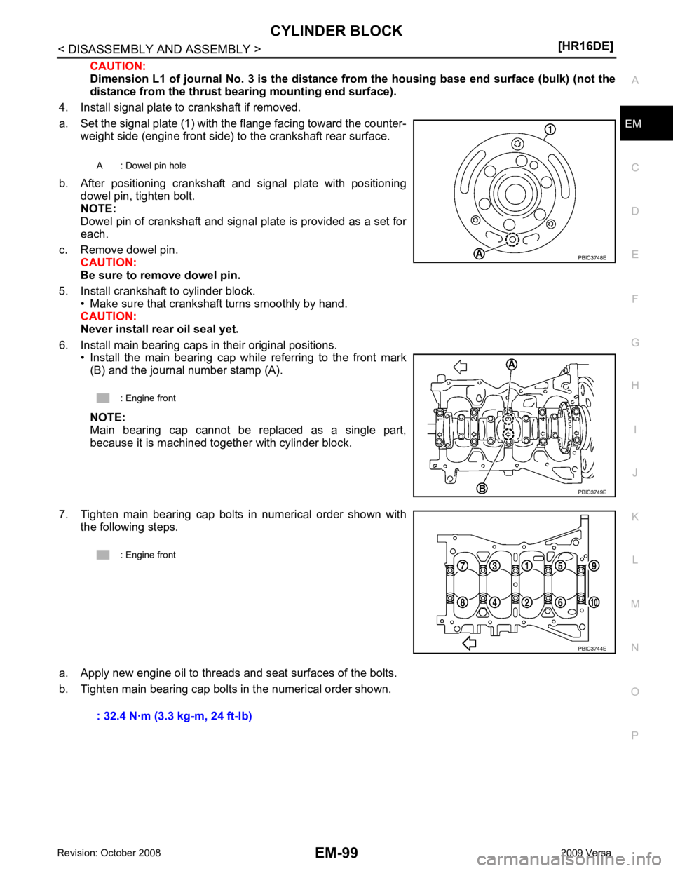
4. Install signal plate to crankshaft if removed.
a. Set the signal plate (1) with the flange facing toward the counter- weight side (engine front side) to the crankshaft rear surface.
b. After positioning crankshaft and signal plate with positioning dowel pin, tighten bolt.
NOTE:
Dowel pin of crankshaft and signal plate is provided as a set for
each.
c. Remove dowel pin. CAUTION:
Be sure to remove dowel pin.
5. Install crankshaft to cylinder block. • Make sure that crankshaft turns smoothly by hand.
CAUTION:
Never install rear oil seal yet.
6. Install main bearing caps in their original positions. • Install the main bearing cap while referring to the front mark(B) and the journal number stamp (A).
NOTE:
Main bearing cap cannot be replaced as a single part,
because it is machined together with cylinder block.
7. Tighten main bearing cap bolts in numerical order shown with the following steps.
a. Apply new engine oil to threads and seat surfaces of the bolts.
b. Tighten main bearing cap bolts in the numerical order shown. A : Dowel pin hole
: Engine front PBIC3749E
Page 3049 of 4331
Inspection " .
14. Tighten connecting rod bolt with the following procedure:
a. Apply new engine oil to the threads and seats of connecting rod bolts.
b. Tighten connecting rod bolts in several steps.
c. Then turn all bolts 60 degrees clockwise (angle tightening). CAUTION:
Confirm the tightening angle by using Tool (A) or protractor.
Avoid judgment by visual inspection without the tool.
• After tightening connecting rod bolts, make sure that crankshaft rotates smoothly.
• Check the connecting rod side clearance. Refer to EM-103, " Inspection " .
15. Install oil pan (upper). Refer to EM-42, " Removal and Installation " .
NOTE:
Install the rear oil seal after installing the oil pan (upper).
16. Install rear oil seal. Refer to EM-77, " REAR OIL SEAL : Removal and Installation " .
17. Install flywheel. • Secure crankshaft with Tool, and tighten bolts crosswise over several times.Tool number : EM03470000 (J-8037)