2009 NISSAN TIIDA lock
[x] Cancel search: lockPage 3058 of 4331
EM
NP
O
HOW TO SELECT PISTON AND BEARING
Description INFOID:0000000004784319
• The identification grade stamped on each part is the grade for the dimension measured in new condition.
This grade cannot apply to reused parts.
• For reused or repaired parts, measure the dimens ion accurately. Determine the grade by comparing the
measurement with the values of each selection table.
• For details of the measurement method of each part , the reuse standards and the selection method of the
selective fitting parts, follow the procedures.
Connecting Rod Bearing INFOID:0000000004784320
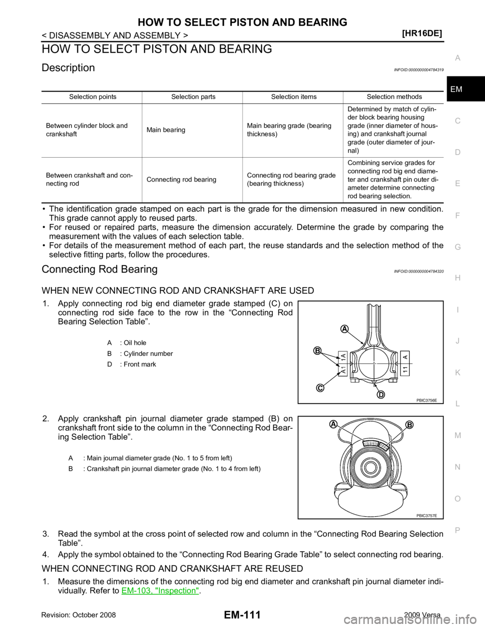
WHEN NEW CONNECTING ROD AND CRANKSHAFT ARE USED 1. Apply connecting rod big end diameter grade stamped (C) on connecting rod side face to the row in the “Connecting Rod
Bearing Selection Table”.
2. Apply crankshaft pin journal diameter grade stamped (B) on crankshaft front side to the column in the “Connecting Rod Bear-
ing Selection Table”.
3. Read the symbol at the cross point of selected ro w and column in the “Connecting Rod Bearing Selection
Table”.
4. Apply the symbol obtained to the “Connecting Rod Bear ing Grade Table” to select connecting rod bearing.
WHEN CONNECTING ROD AND CRANKSHAFT ARE REUSED 1. Measure the dimensions of the connecting rod big end diameter and crankshaft pin journal diameter indi-
vidually. Refer to EM-103, " Inspection " .
Selection points Selection parts Selection items Selection methods
Between cylinder block and
crankshaft Main bearing Main bearing grade (bearing
thickness) Determined by match of cylin-
der block bearing housing
grade (inner diameter of hous-
ing) and crankshaft journal
grade (outer diameter of jour-
nal)
Between crankshaft and con-
necting rod Connecting rod bearing Connecting rod bearing grade
(bearing thickness) Combining service grades for
connecting rod big end diame-
ter and crankshaft pin outer di-
ameter determine connecting
rod bearing selection. A : Oil hole
B : Cylinder number
D : Front mark
Page 3060 of 4331
![NISSAN TIIDA 2009 Service Repair Manual HOW TO SELECT PISTON AND BEARING
EM-113
< DISASSEMBLY AND ASSEMBLY >
[HR16DE] C
D E
F
G H
I
J
K L
M A EM
NP
O
In grinding crankshaft pin to
use undersize bearings, keep the
fillet R (A) [0.8 NISSAN TIIDA 2009 Service Repair Manual HOW TO SELECT PISTON AND BEARING
EM-113
< DISASSEMBLY AND ASSEMBLY >
[HR16DE] C
D E
F
G H
I
J
K L
M A EM
NP
O
In grinding crankshaft pin to
use undersize bearings, keep the
fillet R (A) [0.8](/manual-img/5/57398/w960_57398-3059.png)
HOW TO SELECT PISTON AND BEARING
EM-113
< DISASSEMBLY AND ASSEMBLY >
[HR16DE] C
D E
F
G H
I
J
K L
M A EM
NP
O
In grinding crankshaft pin to
use undersize bearings, keep the
fillet R (A) [0.8 - 1.2 mm (0.031 - 0.047 in)].
Main Bearing INFOID:0000000004784321
HOW TO SELECT MAIN BEARING
When New Cylinder Block and Crankshaft Are Used
1. “Main Bearing Selection Table” rows correspond to main bearing housing grade on left side of cylinder block.
• If there is a corrected stamp mark (B) on cylinder block, use it as a correct reference.
2. Apply main journal diameter grade stamped on crankshaft front side to column in the “Main Bearing Selection Table”.
3. Read the symbol at the cross point of selected row and column in the “Main Bearing Selection Table”.
4. Apply the symbol obtained to the “Main B earing Grade Table” to select main bearing.
NOTE:
Service part is available as a set of both upper and lower.
When Cylinder Block and Crankshaft Are Reused 1. Measure the dimensions of the cylinder block ma in bearing housing inner diameter and crankshaft main
journal diameter individually. Refer to EM-103, " Inspection " .
2. Apply the measured dimension to t he “Main Bearing Selection Table”.
3. Read the symbol at the cross point of selected row and column in the “Main Bearing Selection Table”.
4. Apply the symbol obtained to the “Main B earing Grade Table” to select main bearing.
Bearing undersize table:
Refer to EM-124, " Connecting Rod Bearing " .
PBIC3263J
A : Basic stamp mark
: Engine front PBIC3760E
A : Main journal diameter grade (No. 1 to 5 from left)
B : Crankshaft pin journal diameter grade (No. 1 to 4 from left) PBIC3757E
Page 3068 of 4331
EM
NP
O
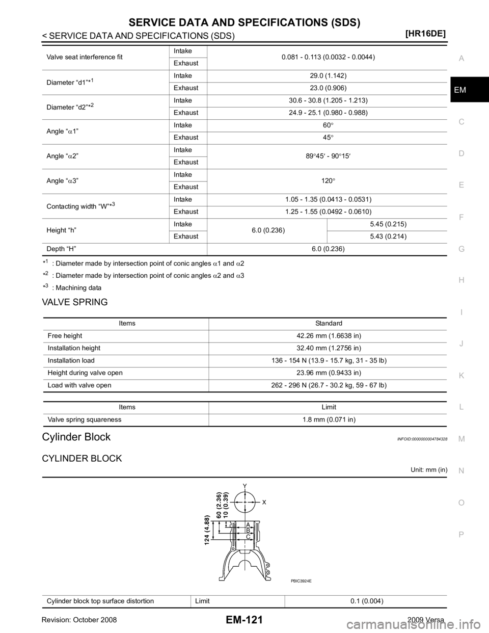
*
1
: Diameter made by intersection point of conic angles α1 and α2
* 2
: Diameter made by intersection point of conic angles α2 and α3
* 3
: Machining data
VALVE SPRING
Cylinder Block INFOID:0000000004784328
CYLINDER BLOCK Unit: mm (in)
Valve seat interference fit
Intake
0.081 - 0.113 (0.0032 - 0.0044)
Exhaust
Diameter “d1”* 1 Intake 29.0 (1.142)
Exhaust 23.0 (0.906)
Diameter “d2”* 2 Intake 30.6 - 30.8 (1.205 - 1.213)
Exhaust 24.9 - 25.1 (0.980 - 0.988)
Angle “ α1” Intake 60
°
Exhaust 45 °
Angle “ α2” Intake
89°45 ′ - 90 °15 ′
Exhaust
Angle “ α3” Intake
120°
Exhaust
Contacting width “W”* 3Intake 1.05 - 1.35 (0.0413 - 0.0531)
Exhaust 1.25 - 1.55 (0.0492 - 0.0610)
Height “h” Intake
6.0 (0.236) 5.45 (0.215)
Exhaust 5.43 (0.214)
Depth “H” 6.0 (0.236)Items Standard
Free height 42.26 mm (1.6638 in)
Installation height 32.40 mm (1.2756 in)
Installation load 136 - 154 N (13.9 - 15.7 kg, 31 - 35 lb)
Height during valve open 23.96 mm (0.9433 in)
Load with valve open 262 - 296 N (26.7 - 30.2 kg, 59 - 67 lb)
Items Limit
Valve spring squareness 1.8 mm (0.071 in) Cylinder block top surface distortion Limit 0.1 (0.004)
Page 3074 of 4331
![NISSAN TIIDA 2009 Service Repair Manual PRECAUTIONS
EM-127
< SERVICE INFORMATION >
[MR18DE] C
D E
F
G H
I
J
K L
M A EM
NP
O
5. When the repair work is completed, return the ignition switch to the
″LOCK ″ position before c NISSAN TIIDA 2009 Service Repair Manual PRECAUTIONS
EM-127
< SERVICE INFORMATION >
[MR18DE] C
D E
F
G H
I
J
K L
M A EM
NP
O
5. When the repair work is completed, return the ignition switch to the
″LOCK ″ position before c](/manual-img/5/57398/w960_57398-3073.png)
PRECAUTIONS
EM-127
< SERVICE INFORMATION >
[MR18DE] C
D E
F
G H
I
J
K L
M A EM
NP
O
5. When the repair work is completed, return the ignition switch to the
″LOCK ″ position before connecting
the battery cables. (At this time, the steering lock mechanism will engage.)
6. Perform a self-diagnosis check of al l control units using CONSULT-III.
Precaution for Procedur e without Cowl Top Cover INFOID:0000000004307110
When performing the procedure after removing cowl top cover, cover
the lower end of windshield.
Precaution for Drain Coolant INFOID:0000000004307112
• Drain coolant when engine is cooled.
Precaution for Disco nnecting Fuel Piping INFOID:0000000004307113
• Before starting work, make sure no fire or spark producing items are in the work area.
• Release fuel pressure before disassembly.
• After disconnecting pipes, plug openings to stop fuel leakage.
Precaution for Removal and Disassembly INFOID:0000000004307114
• When instructed to use special service tools, use the spec ified tools. Always be careful to work safely, avoid
forceful or uninstructed operations.
• Exercise maximum care to avoid damage to mating or sliding surfaces.
• Cover openings of engine system with tape or the equiva lent, if necessary, to seal out foreign materials.
• Mark and arrange disassembly parts in an organized way for easy troubleshooting and assembly.
• When loosening nuts and bolts, as a basic rule, start with the one furthest outside, then the one diagonally opposite, and so on. If the order of loosening is specif ied, do exactly as specified. Power tools may be used
where noted in the step.
Precaution for Inspection, Repair and Replacement INFOID:0000000004307115
• Before repairing or replacing, thoroughly inspect parts. Inspect new replacement parts in the same way, and
replace if necessary.
Precaution for Assembly and Installation INFOID:0000000004307116
• Use torque wrench to tighten bolts or nuts to specification.
• When tightening nuts and bolts, as a basic rule, equally tighten in several different steps starting with the ones in center, then ones on inside and outside diagonally in this order. If the order of tightening is specified,
do exactly as specified.
• Replace with new gasket, packing, oil seal or O-ring.
• Thoroughly wash, clean, and air-blow each part. Carefully check oil or coolant passages for any restriction
and blockage.
• Avoid damaging sliding or mating surfaces. Completely remove foreign materials such as cloth lint or dust. Before assembly, oil sliding surfaces well.
• Release air within route after draining coolant.
• Before starting engine, apply fuel pressure to fuel lines with turning ignition switch ON (with engine stopped). Then make sure that there are no leaks at fuel line connections.
• After repairing, start engine and increase engine speed to check coolant, fuel, oil, and exhaust systems for leakage. PIIB3706J
Page 3082 of 4331
EM
NP
O
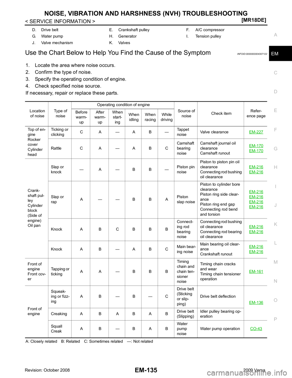
Use the Chart Below to Help You
Find the Cause of the Symptom INFOID:0000000004307122
1. Locate the area where noise occurs.
2. Confirm the type of noise.
3. Specify the operating condition of engine.
4. Check specified noise source.
If necessary, repair or replace these parts.
A: Closely related B: Related C: Sometimes related —: Not related D. Drive belt E. Crankshaft pulley F. A/C compressor
G. Water pump H. Generator I. Tension pulley
J. Valve mechanism K. Valves
Location of noise Type of
noise Operating condition of engine
Source of noise Check item
Refer-
ence page
Before
warm-
up After
warm-
up When
start-
ing When
idling When
racing While
driving
Top of en-
gine
Rocker
cover
Cylinder
head Ticking or
clicking C A — A B —
Tappet
noise Valve clearance
EM-227 Rattle C A — A B C
Camshaft
bearing
noise Camshaft journal oil
clearance
Camshaft runout EM-170 EM-170
Crank-
shaft pul-
ley
Cylinder
block
(Side of
engine)
Oil pan Slap or
knock — A — B B —
Piston pin
noise Piston to piston pin oil
clearance
Connecting rod bushing
oil clearance EM-216 EM-216
Slap or
rap A — — B B A
Piston
slap noise Piston to cylinder bore
clearance
Piston ring side clear-
ance
Piston ring end gap
Connecting rod bend
and torsion EM-216 EM-216
EM-216
EM-216
Knock A B C B B B
Connect-
ing rod
bearing
noise Connecting rod bushing
oil clearance
Connecting rod bearing
oil clearance EM-216 EM-216
Knock A B — A B C
Main bear-
ing noise Main bearing oil clear-
ance
Crankshaft runout EM-216 EM-216
Front of
engine
Front cov-
er Tapping or
ticking A A — B B B Timing
chain and
chain ten-
sioner
noise Timing chain cracks
and wear
Timing chain tensioner
operation EM-161Front of
engine Squeak-
ing or fizz-
ing A B — B — C Drive belt
(Sticking
or slip-
ping) Drive belt deflection
EM-136 Creaking A B A B A B
Drive belt
(Slipping) Idler pulley bearing op-
eration
Squall
Creak A B — B A B Water
pump
noise Water pump operation
CO-43
Page 3084 of 4331
![NISSAN TIIDA 2009 Service Repair Manual DRIVE BELTS
EM-137
< SERVICE INFORMATION >
[MR18DE] C
D E
F
G H
I
J
K L
M A EM
NP
O
1. Hold the hexagonal part (A) of drive belt auto-tensioner (1) with
a box wrench securely. Then move the wre NISSAN TIIDA 2009 Service Repair Manual DRIVE BELTS
EM-137
< SERVICE INFORMATION >
[MR18DE] C
D E
F
G H
I
J
K L
M A EM
NP
O
1. Hold the hexagonal part (A) of drive belt auto-tensioner (1) with
a box wrench securely. Then move the wre](/manual-img/5/57398/w960_57398-3083.png)
DRIVE BELTS
EM-137
< SERVICE INFORMATION >
[MR18DE] C
D E
F
G H
I
J
K L
M A EM
NP
O
1. Hold the hexagonal part (A) of drive belt auto-tensioner (1) with
a box wrench securely. Then move the wrench handle in the
direction of arrow (loosening direction of tensioner).
WARNING:
Never place hand in a location where pinching may occur if
the holding tool accidentally comes off.
2. Insert a rod such as short-length screwdriver approximately 6 mm (0.24 in) in diameter into the hole (B) of retaining boss to fix
drive belt auto-tensioner.
3. Install drive belt. CAUTION:
• Confirm drive belt is completely set to pulleys.
• Check for engine oil, working fluid and engine coolant are not adhered to drive belt and each
pulley groove.
4. Release drive belt auto-tensioner, and apply tension to drive belt.
5. Turn crankshaft pulley clockwise several times to equalize tension between each pulley.
6. Confirm tension of drive belt at indicator (notch on fixed side) is within the possible use range. Refer to
EM-136, " Checking Drive Belts " .
Component INFOID:0000000004307127
Removal and Installation of Drive Belt Auto Tensioner INFOID:0000000004307128
REMOVAL 1. Remove drive belt. Refer to EM-136, " Removal and Installation " .
2. Release the fixed drive belt auto-tensioner pulley.
3. Loosen bolt and remove drive belt auto-tensioner. NOTE: PBIC3936E
1. Front cover 2. Drive belt auto–tensioner 3. Idler pulley (models without A/C)
4. Bracket (models without A/C) 5. Shaft (models without A/C) PBIC4698E
Page 3096 of 4331
EM
NP
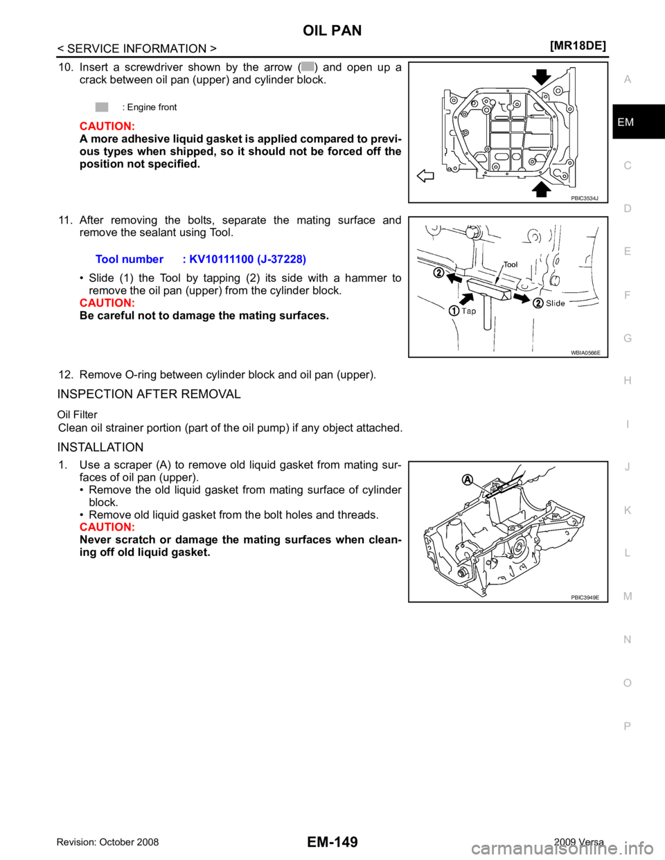
O
10. Insert a screwdriver shown by the arrow ( ) and open up a
crack between oil pan (upper) and cylinder block.
CAUTION:
A more adhesive liquid gasket is applied compared to previ-
ous types when shipped, so it should not be forced off the
position not specified.
11. After removing the bolts, separate the mating surface and remove the sealant using Tool.
• Slide (1) the Tool by tapping (2) its side with a hammer to remove the oil pan (upper) from the cylinder block.
CAUTION:
Be careful not to damage the mating surfaces.
12. Remove O-ring between cylinder block and oil pan (upper).
INSPECTION AFTER REMOVAL
Oil Filter Clean oil strainer portion (part of the oil pump) if any object attached.
INSTALLATION 1. Use a scraper (A) to remove old liquid gasket from mating sur- faces of oil pan (upper).
• Remove the old liquid gasket from mating surface of cylinder
block.
• Remove old liquid gasket from the bolt holes and threads.
CAUTION:
Never scratch or damage the mating surfaces when clean-
ing off old liquid gasket. : Engine front
Page 3097 of 4331
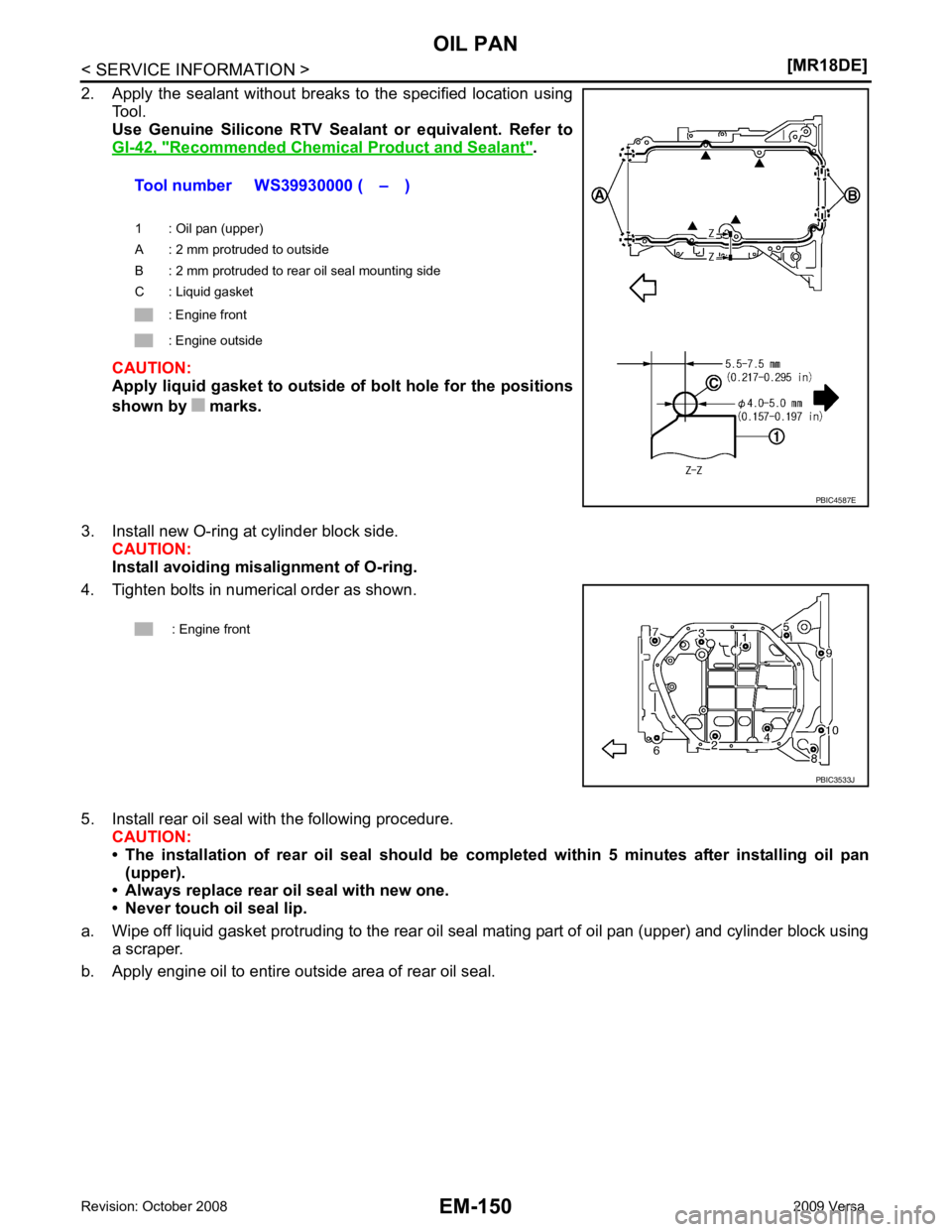
Recommended Chemical
Product and Sealant " .
CAUTION:
Apply liquid gasket to outside of bolt hole for the positions
shown by marks.
3. Install new O-ring at cylinder block side. CAUTION:
Install avoiding misalignment of O-ring.
4. Tighten bolts in numerical order as shown.
5. Install rear oil seal with the following procedure. CAUTION:
• The installation of rear oil seal should be co mpleted within 5 minutes after installing oil pan
(upper).
• Always replace rear oil seal with new one.
• Never touch oil seal lip.
a. Wipe off liquid gasket protruding to the rear oil seal mating part of oil pan (upper) and cylinder block using
a scraper.
b. Apply engine oil to entire outside area of rear oil seal. Tool number WS39930000 ( – )
1 : Oil pan (upper)
A : 2 mm protruded to outside
B : 2 mm protruded to rear oil seal mounting side
C : Liquid gasket
: Engine front
: Engine outside