2009 NISSAN TIIDA lock
[x] Cancel search: lockPage 3179 of 4331
![NISSAN TIIDA 2009 Service Repair Manual EM-232< SERVICE INFORMATION >
[MR18DE]
SERVICE DATA AND SPECIFICATIONS (SDS)
*: Total indicator reading
CYLINDER BLOCK Unit: mm (in)
Camshaft cam height (A)
Intake 44.605 - 44.795 (1.7560 - 1.7635) 44 NISSAN TIIDA 2009 Service Repair Manual EM-232< SERVICE INFORMATION >
[MR18DE]
SERVICE DATA AND SPECIFICATIONS (SDS)
*: Total indicator reading
CYLINDER BLOCK Unit: mm (in)
Camshaft cam height (A)
Intake 44.605 - 44.795 (1.7560 - 1.7635) 44](/manual-img/5/57398/w960_57398-3178.png)
EM-232< SERVICE INFORMATION >
[MR18DE]
SERVICE DATA AND SPECIFICATIONS (SDS)
*: Total indicator reading
CYLINDER BLOCK Unit: mm (in)
Camshaft cam height (A)
Intake 44.605 - 44.795 (1.7560 - 1.7635) 44.405 (1.7482)
Exhaust 43.175 - 43.365 (1.6997 - 1.7072) 42.975 (1.6919)
Camshaft flange 3.877 - 3.925 (0.1526 - 0.1545) —
Camshaft runout [TIR*] Less than 0.02 mm (0.0008) 0.05 (0.0020)
Camshaft sprocket runout [TIR*] — 0.15 (0.0059) SEM671
Top surface distortion Limit 0.1 (0.004)
Cylinder bore Inner diameter Standard Grade No. 1 84.000 - 84.010 (3.3071 - 3.3075)
Grade No. 2 84.010 - 84.020 (3.3075 - 3.3079) PBIC4017E
Page 3191 of 4331
EX
NP
O
SERVICE INFORMATION
PRECAUTIONS
Precaution for Supplemental Restraint System (SRS) "AIR BAG" and "SEAT BELT
PRE-TENSIONER" INFOID:0000000004784390
The Supplemental Restraint System such as “A IR BAG” and “SEAT BELT PRE-TENSIONER”, used along
with a front seat belt, helps to reduce the risk or severi ty of injury to the driver and front passenger for certain
types of collision. This system includes seat belt switch inputs and dual stage front air bag modules. The SRS
system uses the seat belt switches to determine the front air bag deployment, and may only deploy one front
air bag, depending on the severity of a collision and w hether the front occupants are belted or unbelted.
Information necessary to service the system safely is included in the SRS and SB section of this Service Man-
ual.
WARNING:
• To avoid rendering the SRS inoper ative, which could increase the risk of personal injury or death in
the event of a collision which would result in air bag inflation, all maintenance must be performed by
an authorized NISSAN/INFINITI dealer.
• Improper maintenance, including in correct removal and installation of the SRS can lead to personal
injury caused by unintentional act ivation of the system. For removal of Spiral Cable and Air Bag
Module, see the SRS section.
• Do not use electrical test equipm ent on any circuit related to the SRS unless instructed to in this
Service Manual. SRS wiring harnesses can be identi fied by yellow and/or orange harnesses or har-
ness connectors.
• When working near the Airbag Diagnosis Sensor Un it or other Airbag System sensors with the Igni-
tion ON or engine running, DO NOT use air or el ectric power tools or strike near the sensor(s) with a
hammer. Heavy vibration could activate the sensor( s) and deploy the air bag(s), possibly causing
serious injury.
• When using air or electric power tools or hammers , always switch the Ignition OFF, disconnect the
battery, and wait at least 3 minutes before performing any service.
Precaution Necessary for Steering Wh eel Rotation After Battery Disconnect
INFOID:0000000004675325
NOTE:
• This Procedure is applied only to models with Inte lligent Key system and NATS (NISSAN ANTI-THEFT SYS-
TEM).
• Remove and install all control units after disconnecti ng both battery cables with the ignition knob in the
″ LOCK ″ position.
• Always use CONSULT-III to perform self-diagnosis as a part of each function inspection after finishing work.
If DTC is detected, perform trouble diagnosis according to self-diagnostic results.
For models equipped with the Intelligent Key system and NATS , an electrically controlled steering lock mech-
anism is adopted on the key cylinder.
For this reason, if the battery is disconnected or if the battery is discharged, the steering wheel will lock and
steering wheel rotation will become impossible.
If steering wheel rotation is required when battery pow er is interrupted, follow the procedure below before
starting the repair operation.
OPERATION PROCEDURE 1. Connect both battery cables. NOTE:
Supply power using jumper cables if battery is discharged.
2. Use the Intelligent Key or mechanical key to turn the ignition switch to the ″ACC ″ position. At this time, the
steering lock will be released.
3. Disconnect both battery cables. The steering lock will remain released and the steering wheel can be
rotated.
4. Perform the necessary repair operation.
5. When the repair work is completed, return the ignition switch to the ″LOCK ″ position before connecting
the battery cables. (At this time, the steering lock mechanism will engage.)
6. Perform a self-diagnosis check of al l control units using CONSULT-III.
Page 3202 of 4331
FAX
N
O P
2. Without disassembling the hydraulic lines, remove the torque member bolts using power tool. Then repo-
sition the torque member and brake caliper assembly aside with wire. Refer to BR-25 .
CAUTION:
Do not depress brake pedal while brake caliper is removed.
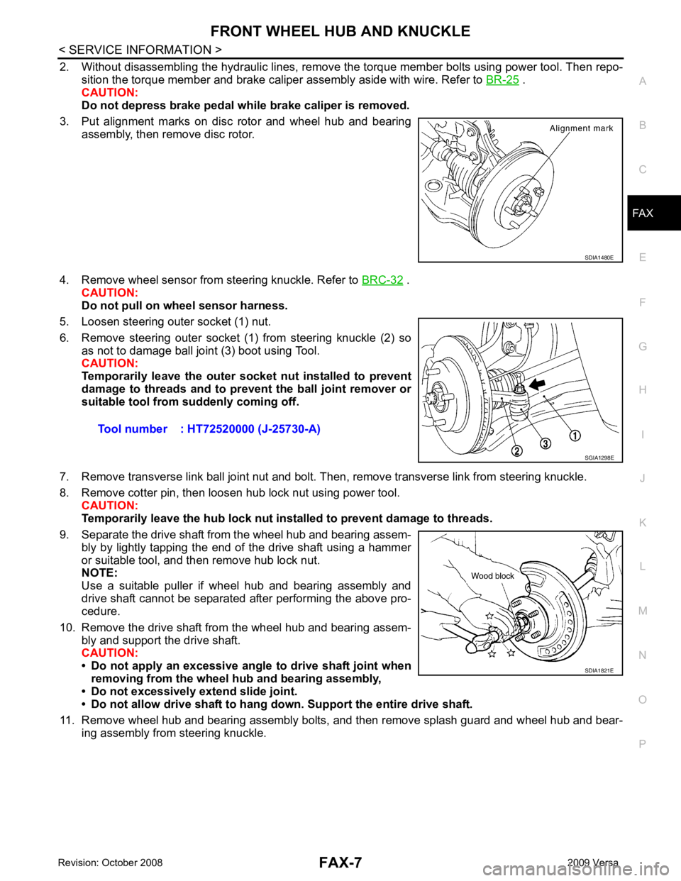
3. Put alignment marks on disc rotor and wheel hub and bearing assembly, then remove disc rotor.
4. Remove wheel sensor from steering knuckle. Refer to BRC-32 .
CAUTION:
Do not pull on wheel sensor harness.
5. Loosen steering outer socket (1) nut.
6. Remove steering outer socket (1) from steering knuckle (2) so as not to damage ball joint (3) boot using Tool.
CAUTION:
Temporarily leave the outer so cket nut installed to prevent
damage to threads and to pr event the ball joint remover or
suitable tool from suddenly coming off.
7. Remove transverse link ball joint nut and bolt. Then, remove transverse link from steering knuckle.
8. Remove cotter pin, then loosen hub lock nut using power tool. CAUTION:
Temporarily leave the hub lock nut inst alled to prevent damage to threads.
9. Separate the drive shaft from the wheel hub and bearing assem- bly by lightly tapping the end of the drive shaft using a hammer
or suitable tool, and then remove hub lock nut.
NOTE:
Use a suitable puller if wheel hub and bearing assembly and
drive shaft cannot be separated after performing the above pro-
cedure.
10. Remove the drive shaft from the wheel hub and bearing assem- bly and support the drive shaft.
CAUTION:
• Do not apply an excessive angle to drive shaft joint when
removing from the wheel hub and bearing assembly,
• Do not excessively extend slide joint.
• Do not allow drive shaft to hang do wn. Support the entire drive shaft.
11. Remove wheel hub and bearing assembly bolts, and then remove splash guard and wheel hub and bear- ing assembly from steering knuckle.
Page 3204 of 4331
FAX
N
O P
FRONT DRIVE SHAFT
On-Vehicle Inspection and Service INFOID:0000000004305845
• Check drive shaft mounting point and joint for looseness and other damage.
• Check boot for cracks and other damage.
Replace or repair components as necessary. Refer to FAX-9, " Removal and Installation (Left Side) " ,
FAX-10, " Removal and Installation (Right Side) " ,
FAX-13, " Disassembly and Assembly (Left Side) " or
FAX-18, " Disas-
sembly and Assembly (Right Side) " .
CAUTION:
Replace entire drive shaft assembly when noi se or vibration occur from drive shaft.
Removal and Installation (Left Side) INFOID:0000000004305846
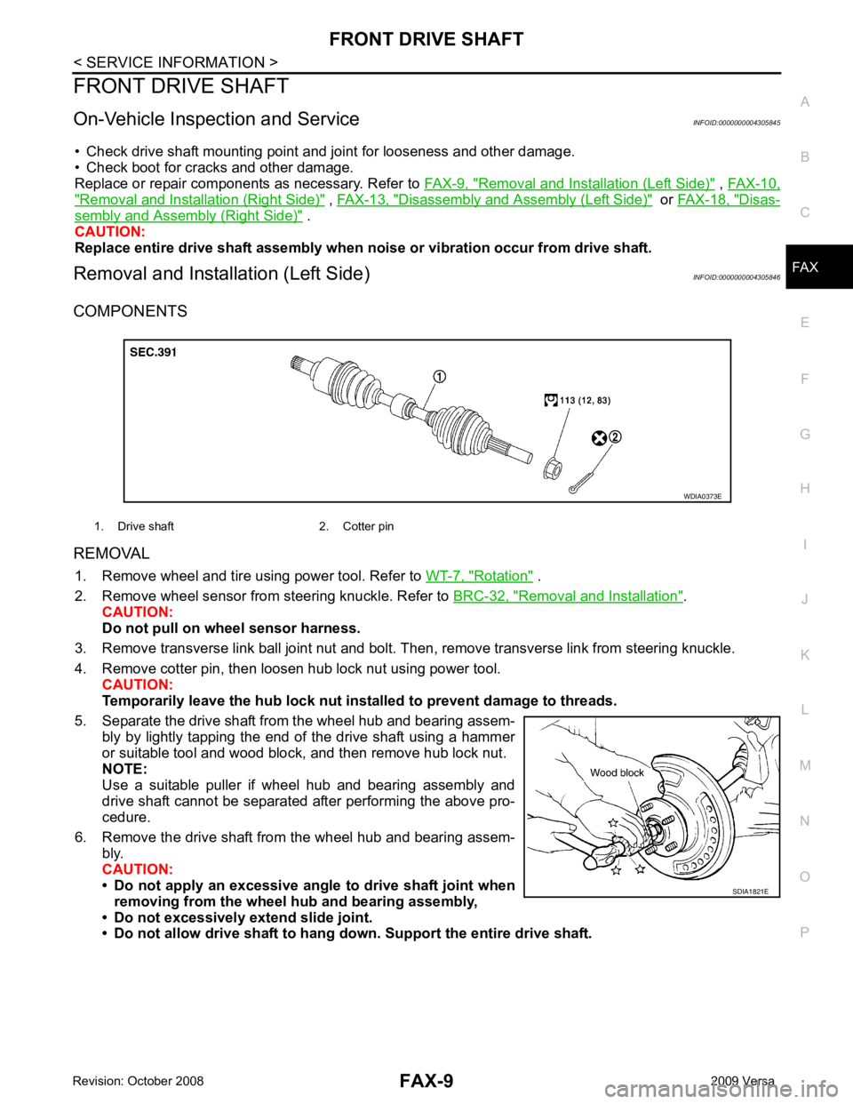
COMPONENTS
REMOVAL 1. Remove wheel and tire using power tool. Refer to WT-7, " Rotation " .
2. Remove wheel sensor from steering knuckle. Refer to BRC-32, " Removal and Installation " .
CAUTION:
Do not pull on wheel sensor harness.
3. Remove transverse link ball joint nut and bolt. Then, remove transverse link from steering knuckle.
4. Remove cotter pin, then loosen hub lock nut using power tool. CAUTION:
Temporarily leave the hub lock nut inst alled to prevent damage to threads.
5. Separate the drive shaft from the wheel hub and bearing assem- bly by lightly tapping the end of the drive shaft using a hammer
or suitable tool and wood block, and then remove hub lock nut.
NOTE:
Use a suitable puller if wheel hub and bearing assembly and
drive shaft cannot be separated after performing the above pro-
cedure.
6. Remove the drive shaft from the wheel hub and bearing assem- bly.
CAUTION:
• Do not apply an excessive angle to drive shaft joint when
removing from the wheel hub and bearing assembly,
• Do not excessively extend slide joint.
• Do not allow drive shaft to hang do wn. Support the entire drive shaft.
1. Drive shaft 2. Cotter pin
Page 3206 of 4331
FAX
N
O P
REMOVAL
1. Remove wheel and tire using power tool. Refer to WT-7, " Rotation " .
2. Remove wheel sensor from steering knuckle. Refer to BRC-32, " Removal and Installation " .
CAUTION:
Do not pull on wheel sensor harness.
3. Remove transverse link ball joint nut and bolt. Then, remove transverse link from steering knuckle.
4. Remove cotter pin, then loosen hub lock nut using power tool. CAUTION:
Temporarily leave the hub lock nut inst alled to prevent damage to threads.
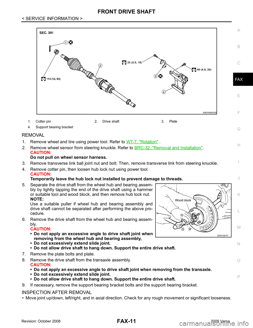
5. Separate the drive shaft from the wheel hub and bearing assem- bly by lightly tapping the end of the drive shaft using a hammer
or suitable tool and wood block, and then remove hub lock nut.
NOTE:
Use a suitable puller if wheel hub and bearing assembly and
drive shaft cannot be separated after performing the above pro-
cedure.
6. Remove the drive shaft from the wheel hub and bearing assem- bly.
CAUTION:
• Do not apply an excessive angle to drive shaft joint when
removing from the wheel hub and bearing assembly,
• Do not excessively extend slide joint.
• Do not allow drive shaft to hang do wn. Support the entire drive shaft.
7. Remove the plate bolts and plate.
8. Remove the drive shaft from the transaxle assembly. CAUTION:
• Do not apply an excessive angle to drive shaf t joint when removing from the transaxle.
• Do not excessively extend slide joint.
• Do not allow drive shaft to hang do wn. Support the entire drive shaft.
9. If necessary, remove the support bearing bracket bolts and the support bearing bracket.
INSPECTION AFTER REMOVAL • Move joint up/down, left/right, and in axial direction. Check for any rough movement or significant looseness.
1. Cotter pin 2. Drive shaft 3. Plate
4. Support bearing bracket B
Page 3223 of 4331
PREPARATION
FL-3
< SERVICE INFORMATION >
C
D E
F
G H
I
J
K L
M A FL
NP
O
PREPARATION
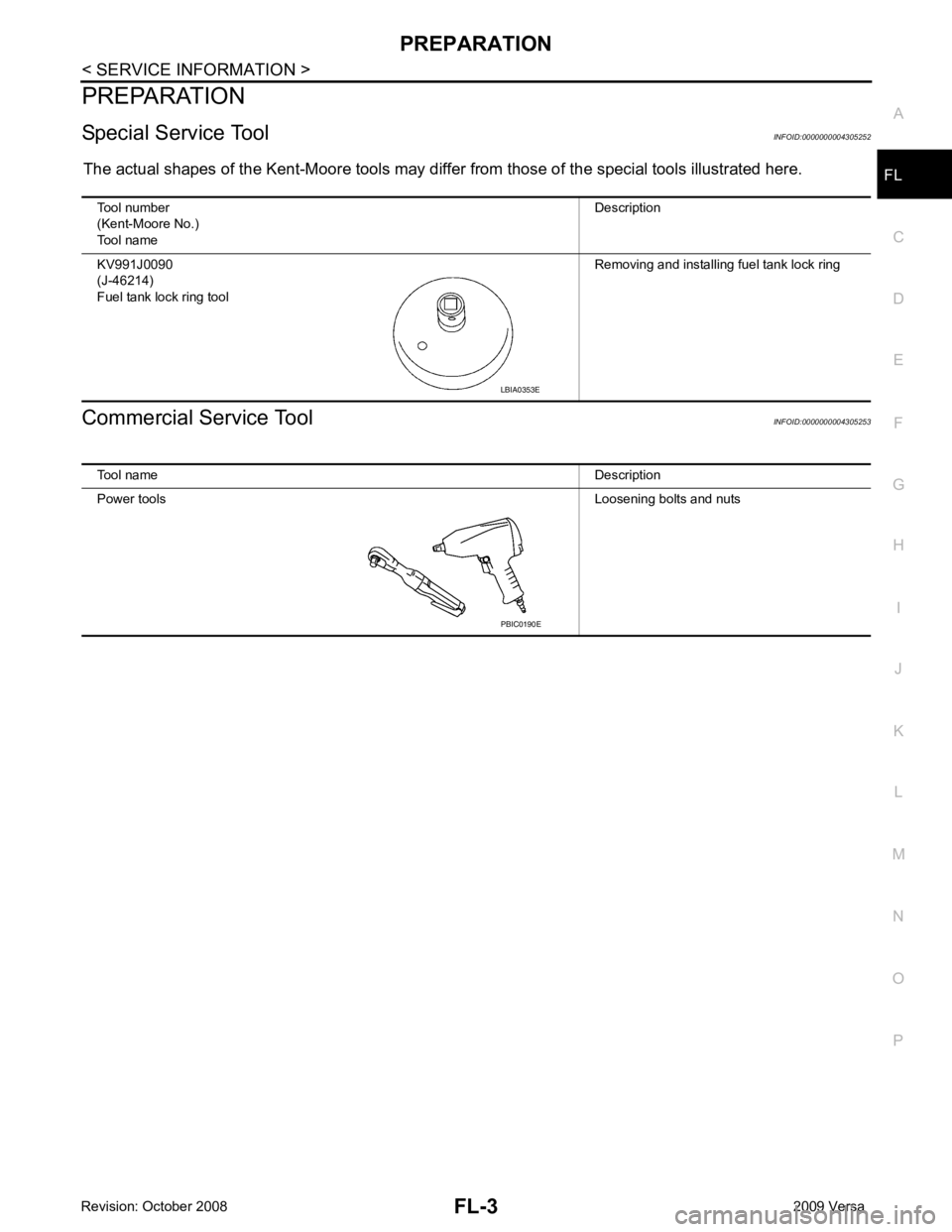
Special Service Tool INFOID:0000000004305252
The actual shapes of the Kent-Moore tools may differ from those of the special tools illustrated here.
Commercial Service Tool INFOID:0000000004305253
Tool number
(Kent-Moore No.)
Tool name Description
KV991J0090
(J-46214)
Fuel tank lock ring tool Removing and installing fuel tank lock ring LBIA0353E
Tool name Description
Power tools Loosening bolts and nuts PBIC0190E
Page 3225 of 4331
FL
NP
O
FUEL LEVEL SENSOR UNIT, FUEL FI
LTER AND FUEL PUMP ASSEMBLY
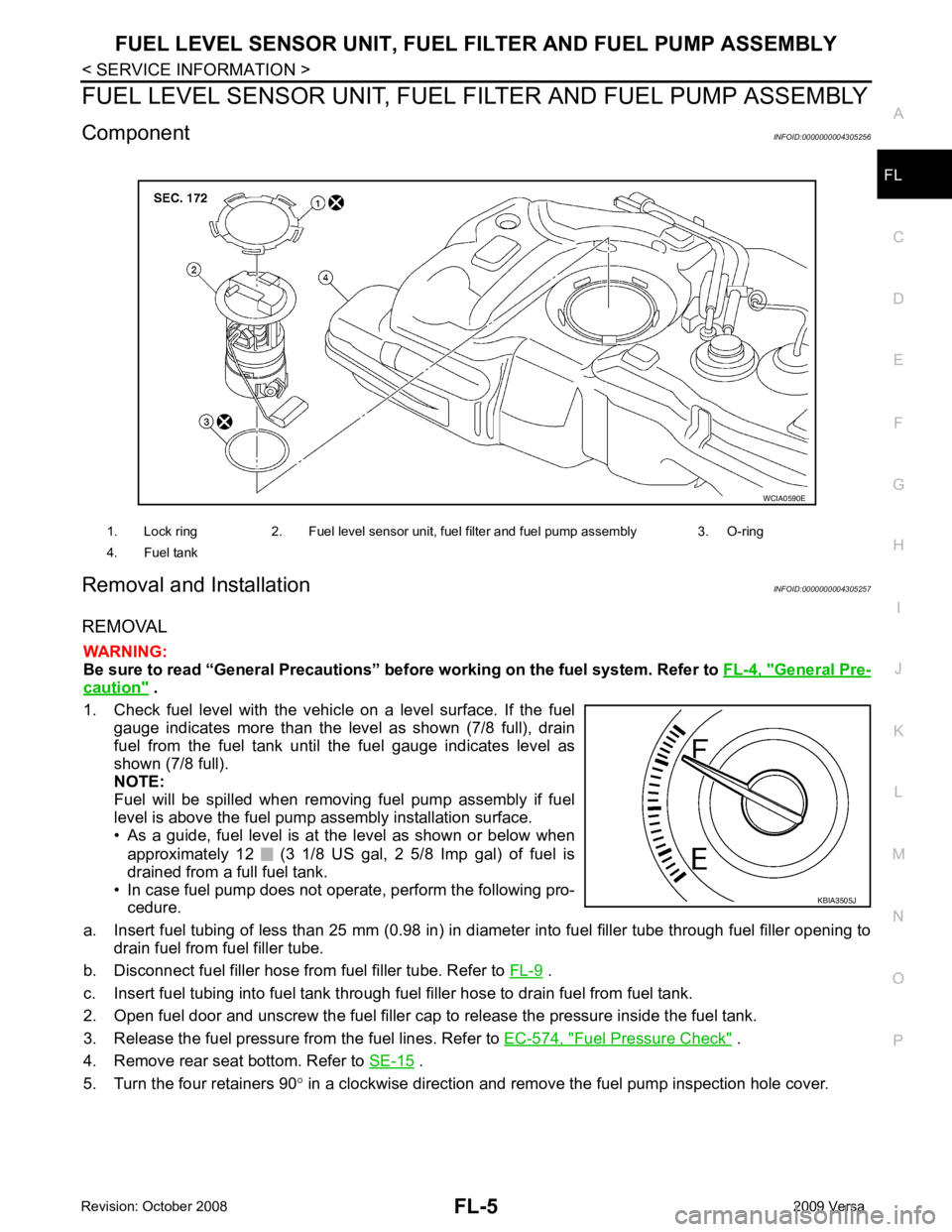
Component INFOID:0000000004305256
Removal and Installation INFOID:0000000004305257
REMOVAL WARNING:
Be sure to read “General Precautions” be fore working on the fuel system. Refer to FL-4, " General Pre-
caution " .
1. Check fuel level with the vehicle on a level surface. If the fuel gauge indicates more than the level as shown (7/8 full), drain
fuel from the fuel tank until the fuel gauge indicates level as
shown (7/8 full).
NOTE:
Fuel will be spilled when removing fuel pump assembly if fuel
level is above the fuel pump assembly installation surface.
• As a guide, fuel level is at the level as shown or below when
approximately 12 (3 1/8 US gal, 2 5/8 Imp gal) of fuel is
drained from a full fuel tank.
• In case fuel pump does not operate, perform the following pro- cedure.
a. Insert fuel tubing of less than 25 mm (0.98 in) in di ameter into fuel filler tube through fuel filler opening to
drain fuel from fuel filler tube.
b. Disconnect fuel filler hose from fuel filler tube. Refer to FL-9 .
c. Insert fuel tubing into fuel tank through fuel filler hose to drain fuel from fuel tank.
2. Open fuel door and unscrew the fuel filler cap to release the pressure inside the fuel tank.
3. Release the fuel pressure from the fuel lines. Refer to EC-574, " Fuel Pressure Check " .
4. Remove rear seat bottom. Refer to SE-15 .
5. Turn the four retainers 90 ° in a clockwise direction and remove the fuel pump inspection hole cover.
1. Lock ring 2. Fuel level sensor unit, fuel filter and fuel pump assembly 3. O-ring
4. Fuel tank
Page 3227 of 4331
FL
NP
O
Make sure that the fuel level sensor
unit, fuel filter and fuel pump is free from defects and foreign materials.
INSTALLATION Installation is in the reverse order of removal.
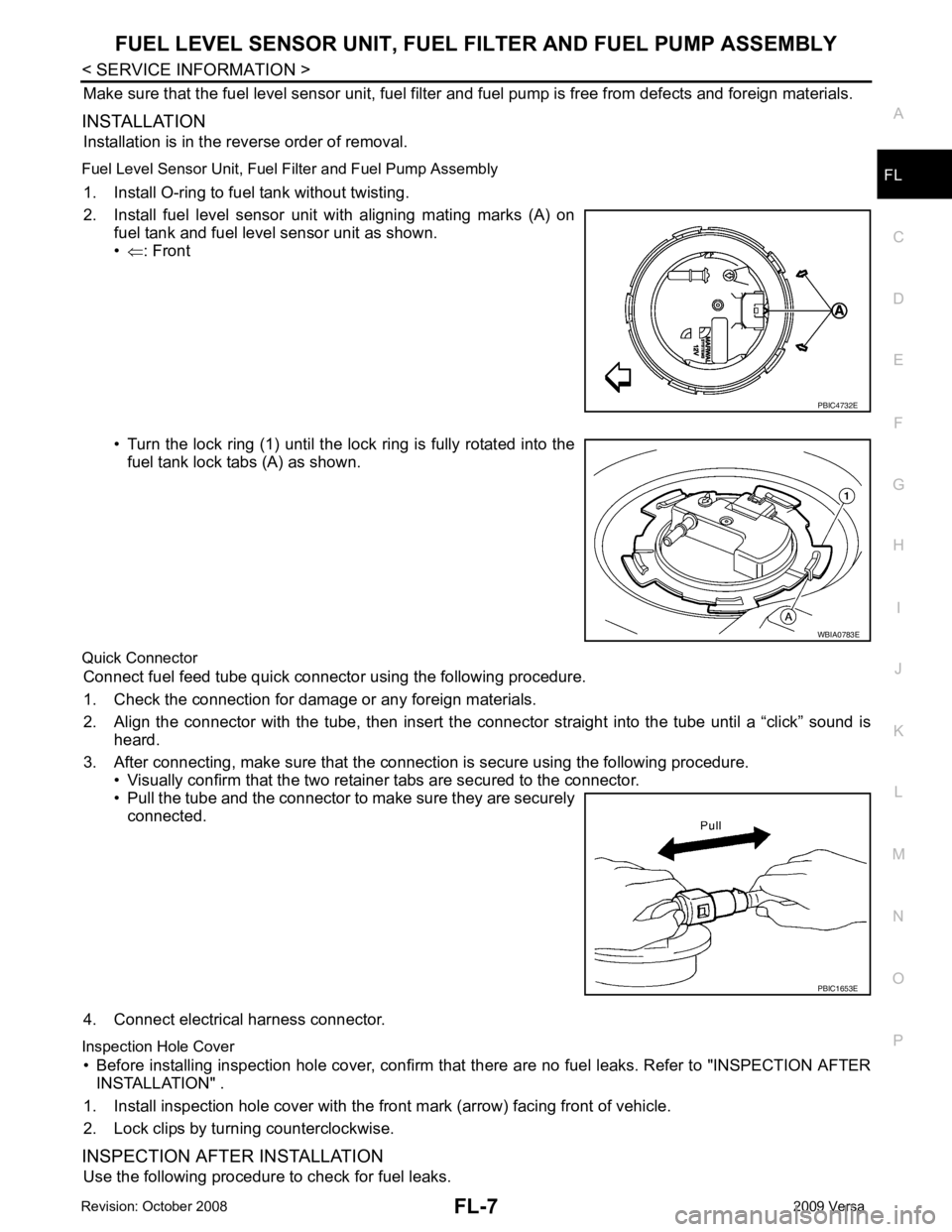
Fuel Level Sensor Unit, Fuel Filter and Fuel Pump Assembly 1. Install O-ring to fuel tank without twisting.
2. Install fuel level sensor unit with aligning mating marks (A) on fuel tank and fuel level sensor unit as shown.
• ⇐ : Front
• Turn the lock ring (1) until the lock ring is fully rotated into the fuel tank lock tabs (A) as shown.
Quick Connector Connect fuel feed tube qui ck connector using the following procedure.
1. Check the connection for damage or any foreign materials.
2. Align the connector with the tube, then insert the c onnector straight into the tube until a “click” sound is
heard.
3. After connecting, make sure that the connection is secure using the following procedure. • Visually confirm that the two retainer tabs are secured to the connector.
• Pull the tube and the connector to make sure they are securely connected.
4. Connect electrical harness connector.
Inspection Hole Cover • Before installing inspection hole cover, confirm that there are no fuel leaks. Refer to "INSPECTION AFTER
INSTALLATION" .
1. Install inspection hole cover with the front mark (arrow) facing front of vehicle.
2. Lock clips by turning counterclockwise.
INSPECTION AFTER INSTALLATION Use the following procedure to check for fuel leaks. WBIA0783E
PBIC1653E