2009 NISSAN TIIDA lock
[x] Cancel search: lockPage 3229 of 4331
FL
NP
O
FUEL TANK
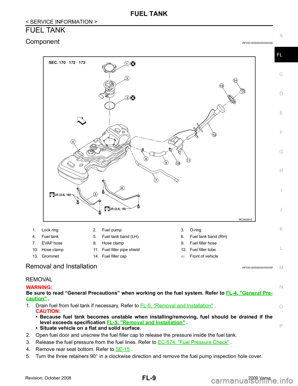
Component INFOID:0000000004305258
Removal and Installation INFOID:0000000004305259
REMOVAL WARNING:
Be sure to read “General Precautions” wh en working on the fuel system. Refer to FL-4, " General Pre-
caution " .
1. Drain fuel from fuel tank if necessary. Refer to FL-5, " Removal and Installation " .
CAUTION:
• Because fuel tank becomes unstable when instal ling/removing, fuel should be drained if the
level exceeds specification FL-5, " Removal and Installation " .
• Situate vehicle on a flat and solid surface.
2. Open fuel door and unscrew the fuel filler cap to release the pressure inside the fuel tank.
3. Release the fuel pressure from the fuel lines. Refer to EC-574, " Fuel Pressure Check " .
4. Remove rear seat bottom. Refer to SE-15 .
5. Turn the three retainers 90 ° in a clockwise direction and remove the fuel pump inspection hole cover.
1. Lock ring 2. Fuel pump 3. O-ring
4. Fuel tank 5. Fuel tank band (LH) 6. Fuel tank band (RH)
7. EVAP hose 8. Hose clamp 9. Fuel filler hose
10. Hose clamp 11. Fuel filler pipe shield 12. Fuel filler tube
13. Grommet 14. Fuel filler cap ⇐Front of vehicle
Page 3237 of 4331
PRECAUTIONS
FSU-3
< SERVICE INFORMATION >
C
D
F
G H
I
J
K L
M A
B FSU
N
O P
5. When the repair work is completed, return the ignition switch to the
″LOCK ″ position before connecting
the battery cables. (At this time, the steering lock mechanism will engage.)
6. Perform a self-diagnosis check of al l control units using CONSULT-III.
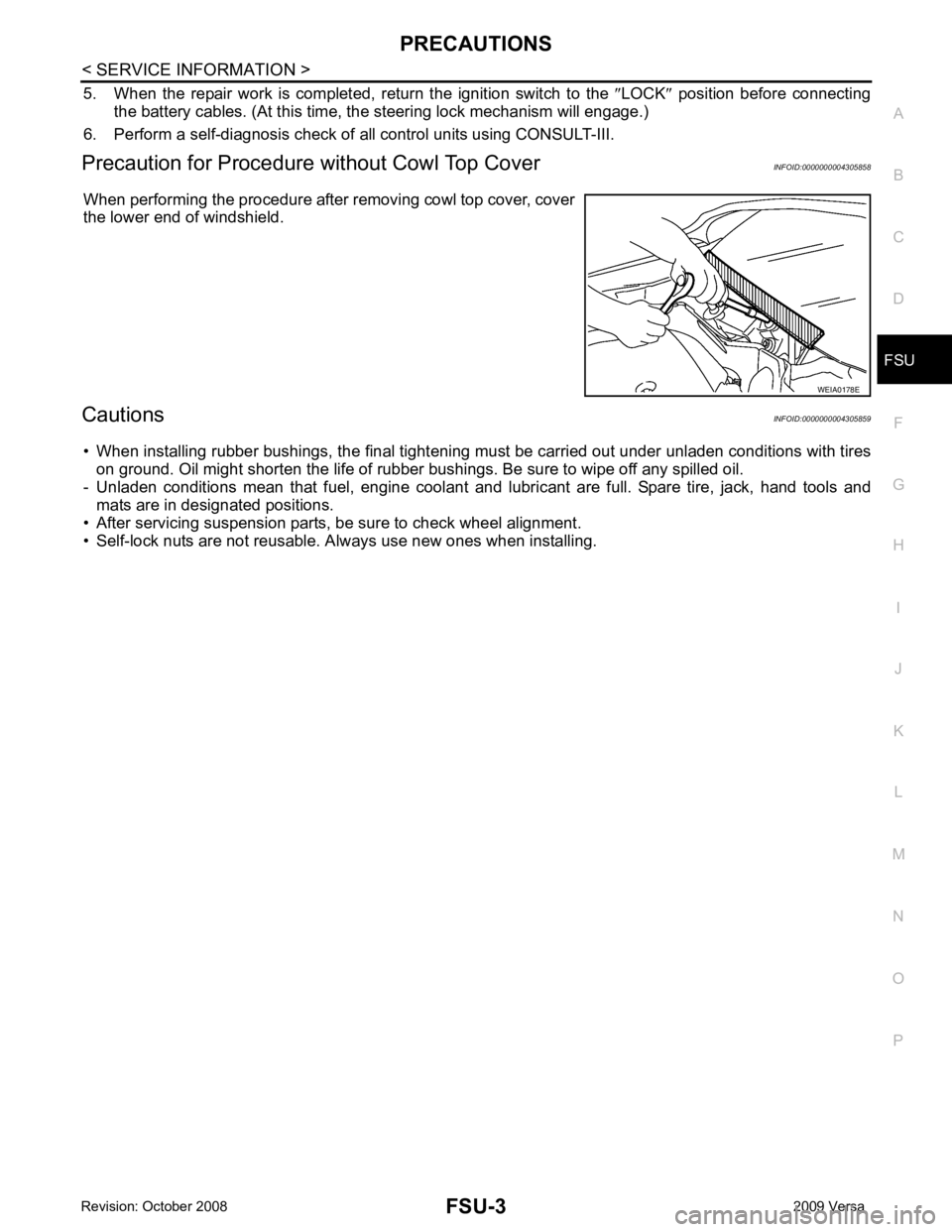
Precaution for Procedur e without Cowl Top Cover INFOID:0000000004305858
When performing the procedure after removing cowl top cover, cover
the lower end of windshield.
Cautions INFOID:0000000004305859
• When installing rubber bushings, the final tightening mu st be carried out under unladen conditions with tires
on ground. Oil might shorten the life of rubber bushings. Be sure to wipe off any spilled oil.
- Unladen conditions mean that fuel, engine coolant and l ubricant are full. Spare tire, jack, hand tools and
mats are in designated positions.
• After servicing suspension parts, be sure to check wheel alignment.
• Self-lock nuts are not reusable. A lways use new ones when installing. WEIA0178E
Page 3246 of 4331
FSU-12< SERVICE INFORMATION >
COIL SPRING AND STRUT
COIL SPRING AND STRUT
Removal and Installation INFOID:0000000004305867
REMOVAL
1. Remove cowl top panel. Refer to EI-22, " Removal and Installation " .
2. Remove front tires using power tool.
3. Remove harness of wheel sensor from strut assembly. Refer to BRC-32, " Removal and Installation " .
CAUTION:
Do not pull on wheel sensor harness.
4. Remove brake hose lock plate. Refer to BR-12, " Rear Brake Tube and Hose " .
5. Remove the nut on the upper side of stabilizer c onnecting rod using power tool, and then remove stabi-
lizer connecting rod from strut assembly.
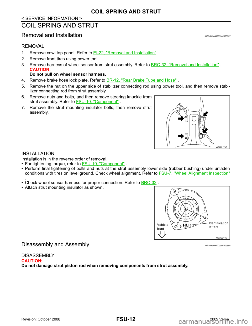
6. Remove nuts and bolts, and then remove steering knuckle from strut assembly. Refer to FSU-10, " Component " .
7. Remove the strut mounting insulator bolts, then remove strut assembly.
INSTALLATION
Installation is in the reverse order of removal.
• For tightening torque, refer to FSU-10, " Component " .
• Perform final tightening of bolts and nuts at the strut assembly lower side (rubber bushing) under unladen
conditions with tires on level ground. Check wheel alignment. Refer to FSU-7, " Wheel Alignment Inspection "
.
• Check wheel sensor harness for proper connection. Refer to BRC-32 .
• Attach strut mounting insulator as shown.
Disassembly and Assembly INFOID:0000000004305868
DISASSEMBLY
CAUTION:
Do not damage strut piston rod when removing components from strut assembly. WEIA0179E
MEIA0014E
Page 3247 of 4331
FSU
N
O P
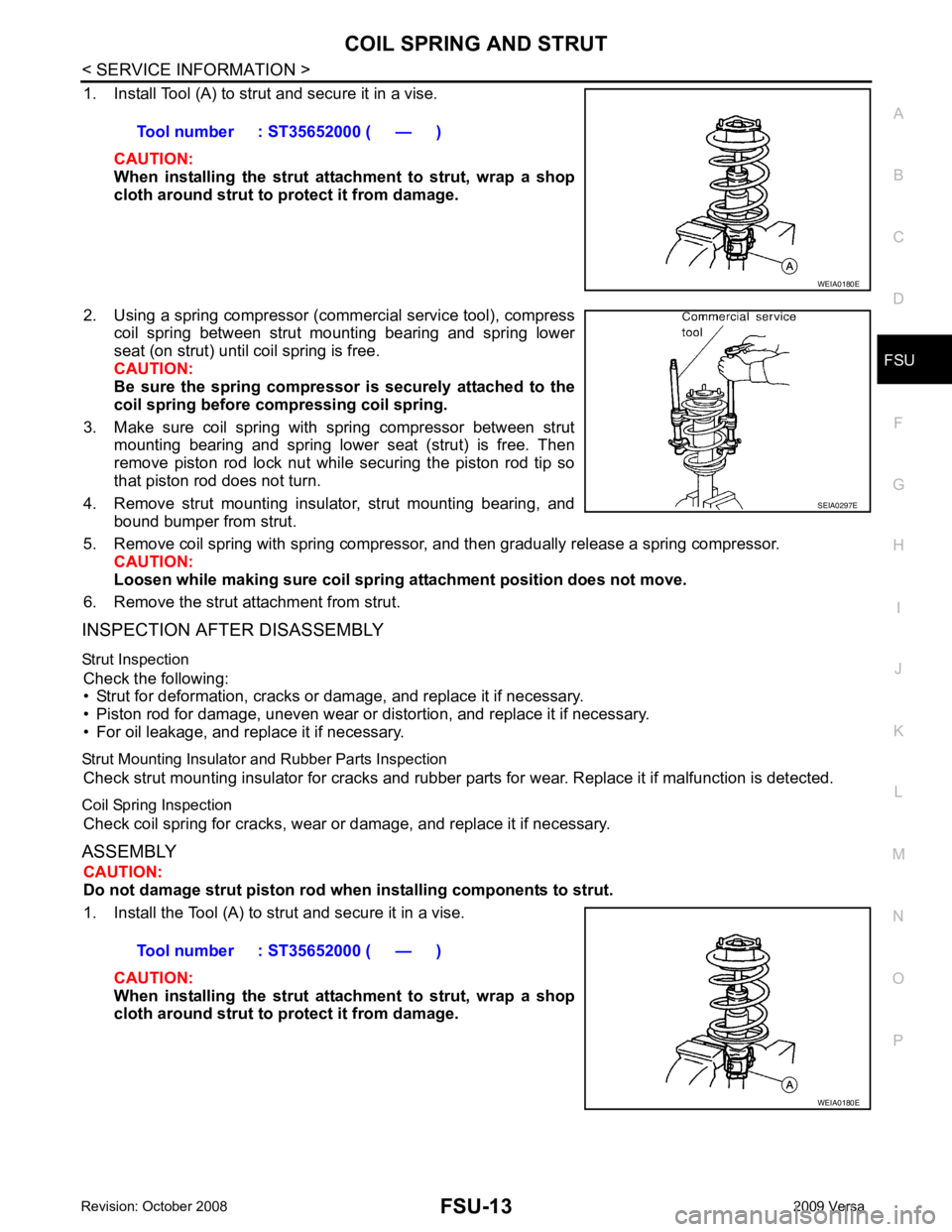
1. Install Tool (A) to strut and secure it in a vise.
CAUTION:
When installing the strut att achment to strut, wrap a shop
cloth around strut to protect it from damage.
2. Using a spring compressor (commercial service tool), compress coil spring between strut mounting bearing and spring lower
seat (on strut) until coil spring is free.
CAUTION:
Be sure the spring compressor is securely attached to the
coil spring before co mpressing coil spring.
3. Make sure coil spring with spring compressor between strut mounting bearing and spring lower seat (strut) is free. Then
remove piston rod lock nut while securing the piston rod tip so
that piston rod does not turn.
4. Remove strut mounting insulator, strut mounting bearing, and bound bumper from strut.
5. Remove coil spring with spring compressor, and then gradually release a spring compressor. CAUTION:
Loosen while making sure coil spring attachment position does not move.
6. Remove the strut attachment from strut.
INSPECTION AFTER DISASSEMBLY
Strut Inspection Check the following:
• Strut for deformation, cracks or damage, and replace it if necessary.
• Piston rod for damage, uneven wear or di stortion, and replace it if necessary.
• For oil leakage, and replace it if necessary.
Strut Mounting Insulator and Rubber Parts Inspection Check strut mounting insulator for cracks and rubber part s for wear. Replace it if malfunction is detected.
Coil Spring Inspection Check coil spring for cracks, wear or damage, and replace it if necessary.
ASSEMBLY CAUTION:
Do not damage strut piston rod when installing components to strut.
1. Install the Tool (A) to strut and secure it in a vise.
CAUTION:
When installing the strut att achment to strut, wrap a shop
cloth around strut to protect it from damage. Tool number : ST35652000 ( — )
SEIA0297E
Page 3248 of 4331
FSU-14< SERVICE INFORMATION >
COIL SPRING AND STRUT
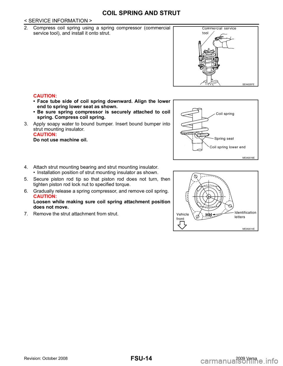
2. Compress coil spring using a spring compressor (commercial service tool), and install it onto strut.
CAUTION:
• Face tube side of coil spri ng downward. Align the lower
end to spring lower seat as shown.
• Be sure spring compressor is securely attached to coil
spring. Compress coil spring.
3. Apply soapy water to bound bumper. Insert bound bumper into strut mounting insulator.
CAUTION:
Do not use machine oil.
4. Attach strut mounting bearing and strut mounting insulator. • Installation position of strut mounting insulator as shown.
5. Secure piston rod tip so that piston rod does not turn, then tighten piston rod lock nut to specified torque.
6. Gradually release a spring compressor, and remove coil spring. CAUTION:
Loosen while making sure co il spring attachment position
does not move.
7. Remove the strut attachment from strut. SEIA0297E
MEIA0016E
MEIA0014E
Page 3256 of 4331
GI
N
O P
2. Use the Intelligent Key or mechanical key to turn the ignition switch to the
″ACC ″ position. At this time, the
steering lock will be released.
3. Disconnect both battery cables. The steering lock will remain released and the steering wheel can be
rotated.
4. Perform the necessary repair operation.
5. When the repair work is completed, return the ignition switch to the ″LOCK ″ position before connecting
the battery cables. (At this time, the steering lock mechanism will engage.)
6. Perform a self-diagnosis check of al l control units using CONSULT-III.
General Precaution INFOID:0000000004307347
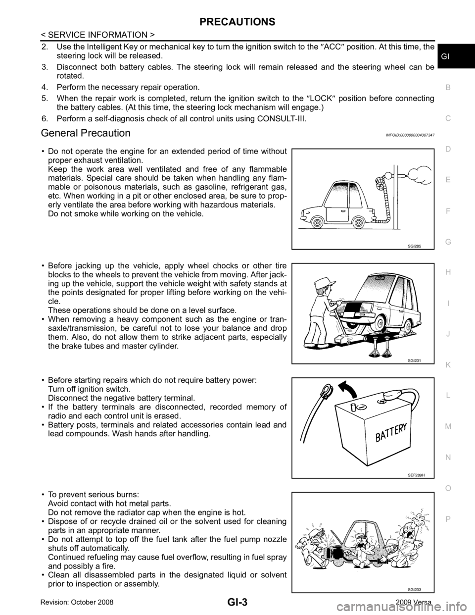
• Do not operate the engine for an extended period of time without proper exhaust ventilation.
Keep the work area well ventilated and free of any flammable
materials. Special care should be taken when handling any flam-
mable or poisonous materials, such as gasoline, refrigerant gas,
etc. When working in a pit or ot her enclosed area, be sure to prop-
erly ventilate the area before working with hazardous materials.
Do not smoke while working on the vehicle.
• Before jacking up the vehicle, apply wheel chocks or other tire blocks to the wheels to prevent t he vehicle from moving. After jack-
ing up the vehicle, support the vehicle weight with safety stands at
the points designated for proper lifting before working on the vehi-
cle.
These operations should be done on a level surface.
• When removing a heavy component such as the engine or tran-
saxle/transmission, be careful not to lose your balance and drop
them. Also, do not allow them to strike adjacent parts, especially
the brake tubes and master cylinder.
• Before starting repairs which do not require battery power: Turn off ignition switch.
Disconnect the negative battery terminal.
• If the battery terminals are disconnected, recorded memory of
radio and each control unit is erased.
• Battery posts, terminals and related accessories contain lead and lead compounds. Wash hands after handling.
• To prevent serious burns: Avoid contact with hot metal parts.
Do not remove the radiator cap when the engine is hot.
• Dispose of or recycle drained oil or the solvent used for cleaning
parts in an appropriate manner.
• Do not attempt to top off the fuel tank after the fuel pump nozzle shuts off automatically.
Continued refueling may cause fuel overflow, resulting in fuel spray
and possibly a fire.
• Clean all disassembled parts in the designated liquid or solvent
prior to inspection or assembly. SGI231
SGI233
Page 3257 of 4331
GI-4< SERVICE INFORMATION >
PRECAUTIONS
• Replace oil seals, gaskets, packings, O-rings, locking wa shers, cotter pins, self-locking nuts, etc. with new
ones.
• Replace inner and outer races of tapered roller bearings and needle bearings as a set.
• Arrange the disassembled parts in accordance with their assembled locations and sequence.
• Do not touch the terminals of electrical com ponents which use microcomputers (such as ECM).
Static electricity may damage internal electronic components.
• After disconnecting vacuum or air hoses, atta ch a tag to indicate the proper connection.
• Use only the fluids and lubricants specified in this manual.
• Use approved bonding agent, sealants or their equivalents when required.
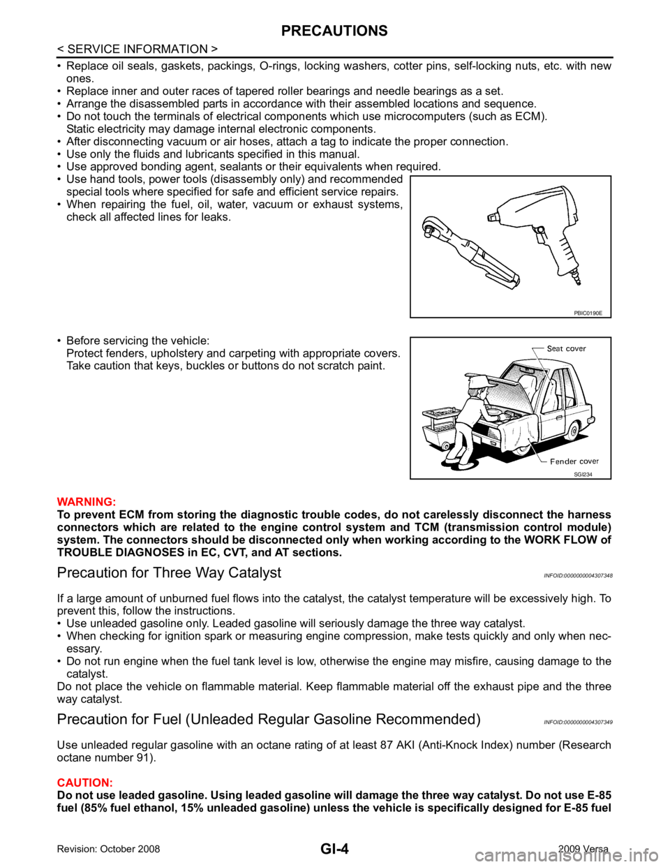
• Use hand tools, power tools (disassembly only) and recommended
special tools where specified for safe and efficient service repairs.
• When repairing the fuel, oil, water, vacuum or exhaust systems, check all affected lines for leaks.
• Before servicing the vehicle: Protect fenders, upholstery and carpeting with appropriate covers.
Take caution that keys, buckles or buttons do not scratch paint.
WARNING:
To prevent ECM from storing the diagnostic tro uble codes, do not carelessly disconnect the harness
connectors which are related to the engine cont rol system and TCM (transmission control module)
system. The connectors should be disconnected on ly when working according to the WORK FLOW of
TROUBLE DIAGNOSES in EC, CVT, and AT sections.
Precaution for Three Way Catalyst INFOID:0000000004307348
If a large amount of unburned fuel flows into the catalyst , the catalyst temperature will be excessively high. To
prevent this, follow the instructions.
• Use unleaded gasoline only. Leaded gasoline will seriously damage the three way catalyst.
• When checking for ignition spark or measuring engine compression, make tests quickly and only when nec-
essary.
• Do not run engine when the fuel tank level is low, otherwise the engine may misfire, causing damage to the
catalyst.
Do not place the vehicle on flammable material. Keep flammable material off the exhaust pipe and the three
way catalyst.
Precaution for Fuel (Unleade d Regular Gasoline Recommended) INFOID:0000000004307349
Use unleaded regular gasoline with an octane rating of at least 87 AKI (Anti-Knock Index) number (Research
octane number 91).
CAUTION:
Do not use leaded gasoline. Using leaded gasoline will damage the three way catalyst. Do not use E-85
fuel (85% fuel ethanol, 15% unl eaded gasoline) unless the vehicle is specifically designed for E-85 fuel PBIC0190E
SGI234
Page 3282 of 4331
GI
N
O P
• Close the relay and probe at the solenoid.
voltage; open is further down the circuit than the solenoid.
no voltage; open is between relay and solenoid (point C).
Any powered circuit can be diagnosed using the approach in the previous example.
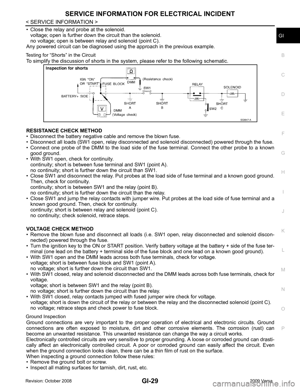
Testing for “Shorts” in the Circuit To simplify the discussion of shorts in the system, please refer to the following schematic.
RESISTANCE CHECK METHOD
• Disconnect the battery negative cable and remove the blown fuse.
• Disconnect all loads (SW1 open, relay disconnected and solenoid disconnected) powered through the fuse.
• Connect one probe of the DMM to the load side of the fuse terminal. Connect the other probe to a known
good ground.
• With SW1 open, check for continuity.
continuity; short is between fuse terminal and SW1 (point A).
no continuity; short is further down the circuit than SW1.
• Close SW1 and disconnect the relay. Put probes at the load side of fuse terminal and a known good ground.
Then, check for continuity.
continuity; short is between SW1 and the relay (point B).
no continuity; short is further down the circuit than the relay.
• Close SW1 and jump the relay contacts with jumper wir e. Put probes at the load side of fuse terminal and a
known good ground. Then, check for continuity.
continuity; short is between relay and solenoid (point C).
no continuity; check solenoid, retrace steps.
VOLTAGE CHECK METHOD
• Remove the blown fuse and disconnect all loads (i .e. SW1 open, relay disconnected and solenoid discon-
nected) powered through the fuse.
• Turn the ignition key to the ON or START position. Veri fy battery voltage at the battery + side of the fuse ter-
minal (one lead on the battery + terminal side of the fuse block and one lead on a known good ground).
• With SW1 open and the DMM leads across both fuse terminals, check for voltage.
voltage; short is between fuse block and SW1 (point A).
no voltage; short is further down the circuit than SW1.
• With SW1 closed, relay and solenoid disconnected and t he DMM leads across both fuse terminals, check for
voltage.
voltage; short is between SW1 and the relay (point B).
no voltage; short is further down the circuit than the relay.
• With SW1 closed, relay contacts jumped with fused jumper wire check for voltage.
voltage; short is down the circuit of the relay or between the relay and the disconnected solenoid (point C).
no voltage; retrace steps and check power to fuse block.
Ground Inspection Ground connections are very important to the proper oper ation of electrical and electronic circuits. Ground
connections are often exposed to moisture, dirt and other corrosive elements. The corrosion (rust) can
become an unwanted resistance. This unwanted re sistance can change the way a circuit works.
Electronically controlled circuits are very sensitive to proper grounding. A loose or corroded ground can drasti-
cally affect an electronically controlled circuit. A poor or corroded ground can easily affect the circuit. Even
when the ground connection looks clean, there can be a thin film of rust on the surface.
When inspecting a ground connection follow these rules:
• Remove the ground bolt or screw.
• Inspect all mating surfaces for tarnish, dirt, rust, etc.