2009 NISSAN TIIDA lock
[x] Cancel search: lockPage 3098 of 4331

EM
NP
O
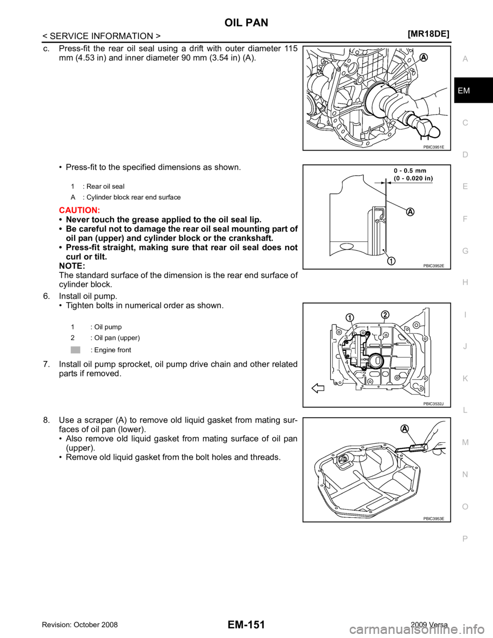
c. Press-fit the rear oil seal usi
ng a drift with outer diameter 115
mm (4.53 in) and inner diameter 90 mm (3.54 in) (A).
• Press-fit to the specified dimensions as shown.
CAUTION:
• Never touch the grease applied to the oil seal lip.
• Be careful not to damage the rear oil seal mounting part of
oil pan (upper) and cylinder block or the crankshaft.
• Press-fit straight, making sure that rear oil seal does not curl or tilt.
NOTE:
The standard surface of the dimens ion is the rear end surface of
cylinder block.
6. Install oil pump. • Tighten bolts in numerical order as shown.
7. Install oil pump sprocket, oil pump drive chain and other related parts if removed.
8. Use a scraper (A) to remove old liquid gasket from mating sur- faces of oil pan (lower).
• Also remove old liquid gasket from mating surface of oil pan (upper).
• Remove old liquid gasket from the bolt holes and threads. PBIC3953E
Page 3108 of 4331

EM
NP
O
Removal and Installation
INFOID:0000000004307143
CAUTION:
The rotating direction indicated in the text indicates all directions seen from the engine front.
REMOVAL 1. Remove front RH wheel. Refer to WT-7, " Rotation " .
2. Remove front fender protector (RH). Refer to EI-24, " Removal and Installation " .
3. Drain engine oil. Refer to LU-17, " Changing Engine Oil " .
CAUTION:
Perform this step when engine is cold.
4. Remove the following parts. • Rocker cover: Refer to EM-153, " Component " .
• Drive belt: Refer to EM-136, " Removal and Installation " .
• Water pump pulley: Refer to CO-43, " Component " .
• Ground cable (between engine bracket (RH) and radiator core support)
5. Support the bottom surface of engine using a transmission jack, and then remove the engine bracket and insulator (RH). Refer to EM-195, " Component " .
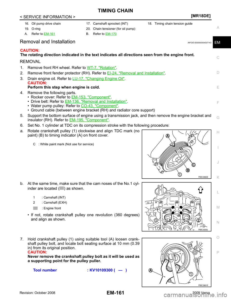
6. Set No. 1 cylinder at TDC on its compression stroke with the following procedure:
a. Rotate crankshaft pulley (1) clockwise and align TDC mark (no paint) (B) to timing indicator (A) on front cover.
b. At the same time, make sure that the cam noses of the No.1 cyl- inder are located ( ) as shown.
• If not, rotate crankshaft pulley one revolution (360 degrees) and align as shown.
7. Hold crankshaft pulley (1) using suitable tool (A) loosen crank- shaft pulley bolt, and locate bolt seating surface at 10 mm (0.39
in) from its original position.
CAUTION:
Never remove the crankshaft pulley bolt as it will be used as
a supporting point for the pulley puller.
16. Oil pump drive chain 17. Camshaft sprocket (INT) 18. Timing chain tension guide
19. O-ring 20. Chain tensioner (for oil pump)
A. Refer to EM-161 B. Refer to
EM-170 C : White paint mark (Not use for service)
Page 3115 of 4331
![NISSAN TIIDA 2009 Service Repair Manual EM-168< SERVICE INFORMATION >
[MR18DE]
TIMING CHAIN
• Install front oil seal (2) using a suitable tool with outer diameter 57 mm (2.24 in) and inner diameter 45 mm (1.77 in) (A) to the
dimension sho NISSAN TIIDA 2009 Service Repair Manual EM-168< SERVICE INFORMATION >
[MR18DE]
TIMING CHAIN
• Install front oil seal (2) using a suitable tool with outer diameter 57 mm (2.24 in) and inner diameter 45 mm (1.77 in) (A) to the
dimension sho](/manual-img/5/57398/w960_57398-3114.png)
EM-168< SERVICE INFORMATION >
[MR18DE]
TIMING CHAIN
• Install front oil seal (2) using a suitable tool with outer diameter 57 mm (2.24 in) and inner diameter 45 mm (1.77 in) (A) to the
dimension shown.
CAUTION:
• Be careful not to damage front cover and crankshaft.
• Press-fit oil seal straight to avoid causing burrs or tilting.
• Never touch grease applied onto oil seal lip.
12. Install new O-ring to cylinder block. CAUTION:
Be sure O-rings are aligned properly.
13. Apply the sealant without breaks to the specified location using Tool.
Use Genuine Silicone RTV Seal ant or equivalent. Refer to
GI-42, " Recommended Chemical
Product and Sealant " .
14. Make sure that matching marks of timing chain and each sprocket are still aligned. CAUTION:
• Make sure O-ring on cylinder block is correctly installed.
• Be careful not to damage front oil seal by interference with front end of crankshaft.
1 : Front cover
: Engine front
Within 0.3 mm (0.012 in) toward engine front
Within 0.5 mm (0.020 in) toward engine rear PBIC3729E
Tool number WS39930000 ( – )
A : Liquid gasket application area
B : Liquid gasket
: Engine outside PBIC3959E
Page 3116 of 4331
![NISSAN TIIDA 2009 Service Repair Manual TIMING CHAIN
EM-169
< SERVICE INFORMATION >
[MR18DE] C
D E
F
G H
I
J
K L
M A EM
NP
O
15. Install front cover, and tighten bolts in two stages to specified
torque in numerical order as shown. NISSAN TIIDA 2009 Service Repair Manual TIMING CHAIN
EM-169
< SERVICE INFORMATION >
[MR18DE] C
D E
F
G H
I
J
K L
M A EM
NP
O
15. Install front cover, and tighten bolts in two stages to specified
torque in numerical order as shown.](/manual-img/5/57398/w960_57398-3115.png)
TIMING CHAIN
EM-169
< SERVICE INFORMATION >
[MR18DE] C
D E
F
G H
I
J
K L
M A EM
NP
O
15. Install front cover, and tighten bolts in two stages to specified
torque in numerical order as shown.
CAUTION:
• Attaching should be done wi thin 5 minutes after liquid
gasket application.
• Be sure to wipe off any excessive liquid gasket leaking.
NOTE:
Installation position of bolts is as shown.
16. Install crankshaft pulley using the following procedure.
a. Install crankshaft pulley. CAUTION:
• Never damage front oil seal lip section.
• If needed use a plastic hammer, tap on its cente r portion (not circumference) to seat crankshaft
pulley.
b. Apply new engine oil to thread and seat surfaces of crankshaft pulley bolt.
c. Secure crankshaft pulley (1) using Tool (A).
d. Tighten crankshaft pulley bolt in two steps.
• For angle tightening, put a paint mark (B) on crankshaft pulley(2), matching with any one of six easy to recognize angle
marks (A) on crankshaft pulley bolt flange (1).
• Turn 60 degrees clockwise (angle tightening).
• Check the tightening angle with movement of one angle mark.
e. Make sure that crankshaft rotates clockwise smoothly.
17. Installation of the remaining components is in the reverse order of removal. M6 bolts : No. 1
M10 bolts : No. 6, 7, 10, 11, 14
M12 bolts : No. 2, 4, 8, 12
M8 bolts : Except the above PBIC3164J
Tool Number : KV10109300 ( — )
Step 1 : 29.4 N·m (3.0 kg-m, 22 ft-lb)
Step 2 : 60 ° clockwise PBIC3961E
PBIC3963E
Page 3120 of 4331
![NISSAN TIIDA 2009 Service Repair Manual CAMSHAFT
EM-173
< SERVICE INFORMATION >
[MR18DE] C
D E
F
G H
I
J
K L
M A EM
NP
O
• Measure the inner diameter of camshaft bracket with a bore gauge
(A).
CAMSHAFT JOURNAL OIL CLEARANCE
• (Oil clear NISSAN TIIDA 2009 Service Repair Manual CAMSHAFT
EM-173
< SERVICE INFORMATION >
[MR18DE] C
D E
F
G H
I
J
K L
M A EM
NP
O
• Measure the inner diameter of camshaft bracket with a bore gauge
(A).
CAMSHAFT JOURNAL OIL CLEARANCE
• (Oil clear](/manual-img/5/57398/w960_57398-3119.png)
CAMSHAFT
EM-173
< SERVICE INFORMATION >
[MR18DE] C
D E
F
G H
I
J
K L
M A EM
NP
O
• Measure the inner diameter of camshaft bracket with a bore gauge
(A).
CAMSHAFT JOURNAL OIL CLEARANCE
• (Oil clearance) = (Camshaft bracket inner diameter) – (Camshaft journal diameter)
• If it exceeds the limit, replace camshaft or cylinder head, or both. NOTE:
Camshaft bracket cannot be replaced as a single part , because it is machined together with cylinder head.
Replace whole cylinder head assembly.
Camshaft End Play 1. Install camshaft in cylinder head.
2. Install dial indicator in thrust direction on front end of camshaft. Read the end play of dial indicator (A) when camshaft is moved
forward/backward (in direction to axis).
• Measure the following parts if out of the standard.
- Dimension (A) for groove of cylinder head No. 1 journal
- Dimension (B) for camshaft flange
• Apply the standards above, and then replace camshaft and/or cylinder head, if necessary.
Camshaft Sprocket Runout 1. Put V-block on precise flat table, and support No. 2 and 5 journals of camshaft. CAUTION:
Never support No. 1 journal (on the side of cam shaft sprocket) because it has a different diameter
from the other four locations. B : Measuring direction of inner diameter
Standard: No. 1 : 28.000 - 28.021 mm (1.1024 - 1.1032 in)
No. 2, 3, 4, 5 : 25.000 - 25.021 mm (0.9843 - 0.9851 in) PBIC3180J
Standard:
No. 1 : 0.045 - 0.086 mm (0.0018 - 0.0034 in)
No. 2, 3, 4, 5 : 0.030 - 0.071 mm (0.0012 - 0.0028 in)
Limit:
: 0.15 mm (0.0059 in)
Standard : 0.075 - 0.153 mm (0.0030 - 0.0060 in)
Limit : 0.24 mm (0.0094 in) PBIC3181J
Standard : 4.000 - 4.030 mm (0.1575 - 0.1587 in)
Standard : 3.877 - 3.925 mm (0.1526 - 0.1545 in) PBIC3183J
Page 3123 of 4331
![NISSAN TIIDA 2009 Service Repair Manual EM-176< SERVICE INFORMATION >
[MR18DE]
CAMSHAFT
5. Install camshaft bracket bolts in three stage in numerical order as shown.
• There are two types of bolts. Locate the bolts as shown.
6. T NISSAN TIIDA 2009 Service Repair Manual EM-176< SERVICE INFORMATION >
[MR18DE]
CAMSHAFT
5. Install camshaft bracket bolts in three stage in numerical order as shown.
• There are two types of bolts. Locate the bolts as shown.
6. T](/manual-img/5/57398/w960_57398-3122.png)
EM-176< SERVICE INFORMATION >
[MR18DE]
CAMSHAFT
5. Install camshaft bracket bolts in three stage in numerical order as shown.
• There are two types of bolts. Locate the bolts as shown.
6. Tighten all bolts in numerical order in three steps.
7. Install the camshaft sprocket (INT) (2) to the camshaft (INT). NOTE:
Align the matching mark (A) applied during removal. Securely
align the knock pin and the pin hole, and then install them.
8. Tighten camshaft (INT) sprocket bolt. NOTE:
Secure the hexagonal part of camshaft (INT) using wrench to tighten bolt.
9. Turn 67 degrees clockwise (angle tightening) using Tool (B).
CAUTION:
Never judge by visual inspect ion without an angle wrench.
: Engine front
M6 bolts [thread length: 57.5 mm (2.264 in)] : 13, 14 and 15
M6 bolts [thread length: 35.00 mm (1.378 in)] : Except the above
Step 1 : 1.96 N·m (0.20 kg-m, 17 in-lb)
Step 2 : 5.88 N·m (0.60 kg-m, 52 in-lb)
Step 3 : 9.5 N·m (0.97 kg-m, 84 in-lb)
1 : Camshaft bracket : Engine front PBIC3176J
PBIC3992J
Camshaft sprocket bolt (INT) : 35.0 N·m (3.6 kg-m, 26 ft-lb)
1 : Camshaft sprocket (INT)
A : Camshaft (INT) hexagonal part
Tool number : KV10112100 (BT-8653-A) PBIC3455J
Page 3125 of 4331

Component " .
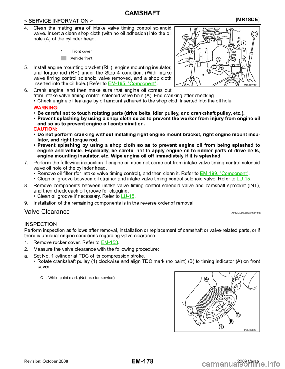
6. Crank engine, and then make sure that engine oil comes out from intake valve timing control solenoid valve hole (A). End cranking after checking.
• Check engine oil leakage by oil amount adhered to the shop cloth inserted into the oil hole.
WARNING:
• Be careful not to touch rotating parts (drive be lts, idler pulley, and crankshaft pulley, etc.).
• Prevent splashing by using a shop cloth so as to prevent the worker from injury from engine oil
and so as to prevent engi ne oil contamination.
CAUTION:
• Do not perform cranking without installing right engine mount bracket, right engine mount insu-
lator, and right torque rod.
• Prevent splashing by using a shop cloth so as to prevent engine oil from being splashed to
engine and vehicle. Especially, be careful not to apply engine oil to rubber parts of drive belts,
engine mounting insulator, etc. Wipe engi ne oil off immediately if it is splashed.
7. Perform the following inspection if engine oil does not come out from intake valve timing control solenoid valve oil hole of the cylinder head.
• Remove oil filter (for intake valve timing control), and then clean it. Refer to EM-199, " Component " .
• Clean oil groove between oil strainer and intake valve timing control solenoid valve. Refer to LU-15 .
8. Remove components between intake valve timing c ontrol solenoid valve and camshaft sprocket (INT),
and then check each oil groove for clogging.
• Clean oil groove if necessary. Refer to LU-15 .
9. Installation of the remaining components is in the reverse order of removal
Valve Clearance INFOID:0000000004307146
INSPECTION
Perform inspection as follows after removal, installation or replacement of camshaft or valve-related parts, or if
there is unusual engine conditions regarding valve clearance.
1. Remove rocker cover. Refer to EM-153 .
2. Measure the valve clearance with the following procedure:
a. Set No. 1 cylinder at TDC of its compression stroke. • Rotate crankshaft pulley (1) clockwise and align TDC mark (no paint) (B) to timing indicator (A) on front
cover. 1 : Front cover
:Vehicle front
Page 3130 of 4331
![NISSAN TIIDA 2009 Service Repair Manual OIL SEAL
EM-183
< SERVICE INFORMATION >
[MR18DE] C
D E
F
G H
I
J
K L
M A EM
NP
O
• Drive belt; Refer to
EM-136, " Component " .
• Crankshaft pulley; Refer to EM-160, " Component " .
2. Remove fr NISSAN TIIDA 2009 Service Repair Manual OIL SEAL
EM-183
< SERVICE INFORMATION >
[MR18DE] C
D E
F
G H
I
J
K L
M A EM
NP
O
• Drive belt; Refer to
EM-136, " Component " .
• Crankshaft pulley; Refer to EM-160, " Component " .
2. Remove fr](/manual-img/5/57398/w960_57398-3129.png)
OIL SEAL
EM-183
< SERVICE INFORMATION >
[MR18DE] C
D E
F
G H
I
J
K L
M A EM
NP
O
• Drive belt; Refer to
EM-136, " Component " .
• Crankshaft pulley; Refer to EM-160, " Component " .
2. Remove front oil seal using a suitable tool. CAUTION:
Be careful not to damage front cover and crankshaft.
INSTALLATION 1. Apply new engine oil to new front oil seal joint surface and seal lip.
2. Install front oil seal so that each seal lip is oriented as shown.
• Install front oil seal (2) using a suitable tool with outer diameter57 mm (2.24 in) and inner diameter 45 mm (1.77 in) (A) to the
dimension as shown.
CAUTION:
• Be careful not to damage front cover and crankshaft.
• Press-fit oil seal straight to avoid causing burrs or tilting.
• Do not touch grease applied on oil seal lip.
3. Installation of the remaining components is in the reverse order of removal.
Removal and Installation of Rear Oil Seal INFOID:0000000004307149
REMOVAL 1. Remove transaxle assembly. Refer to MT-58 (M/T models),
AT-232 (A/T models),
CVT-182 or
CVT-354 (CVT models).
2. Remove clutch cover and clutch disk (M/T models). Refer to CL-15 .
3. Remove drive plate (A/T or CVT models) or flywheel (M/T models). Refer to EM-199, " Component " .
4. Remove rear oil seal with a suitable tool. CAUTION:
Be careful not to damage crankshaft and cylinder block.
INSTALLATION 1. Apply the liquid gasket lightly to entire outside area of new rear oil seal. Use Genuine Silicone RTV Seal ant or equivalent. Refer to GI-42, " Recommended Chemical Prod-
uct and Sealant " .
A : Dust seal lip
B : Oil seal lip
: Engine front
: Engine rear PBIC3485J
1 : Front cover
: Engine front
Within 0.3 mm (0.012 in) toward engine front
Within 0.5 mm (0.020 in) toward engine rear PBIC3729E