2009 NISSAN TIIDA lock
[x] Cancel search: lockPage 3131 of 4331
![NISSAN TIIDA 2009 Service Repair Manual EM-184< SERVICE INFORMATION >
[MR18DE]
OIL SEAL
2. Install rear oil seal so that each seal lip is oriented as shown.
• Install rear oil seal with a suitable tool with an outer diameter115 NISSAN TIIDA 2009 Service Repair Manual EM-184< SERVICE INFORMATION >
[MR18DE]
OIL SEAL
2. Install rear oil seal so that each seal lip is oriented as shown.
• Install rear oil seal with a suitable tool with an outer diameter115](/manual-img/5/57398/w960_57398-3130.png)
EM-184< SERVICE INFORMATION >
[MR18DE]
OIL SEAL
2. Install rear oil seal so that each seal lip is oriented as shown.
• Install rear oil seal with a suitable tool with an outer diameter115 mm (4.53 in) and inner diameter 90 mm (3.54 in) (A).
CAUTION:
• Be careful not to damage crankshaft and cylinder block.
• Press-fit oil seal straight to avoid causing burrs or tilt-
ing.
• Do not touch grease applied onto oil seal lip.
• Install rear oil seal (1) to the position as shown.
NOTE:
The standard surface of the dimension is the rear end surface of
cylinder block.
3. Installation of the remaining components is in the reverse order of removal. A : Dust seal lip
B : Oil seal lip
: Engine outside
: Engine inside PBIC3485J
PBIC3951E
A : Rear end surface of cylinder block
PBIC3761E
Page 3134 of 4331
![NISSAN TIIDA 2009 Service Repair Manual CYLINDER HEAD
EM-187
< SERVICE INFORMATION >
[MR18DE] C
D E
F
G H
I
J
K L
M A EM
NP
O
4. Remove drive belt. Refer to
EM-136, " Removal and Installation " .
5. Remove the following components and rela NISSAN TIIDA 2009 Service Repair Manual CYLINDER HEAD
EM-187
< SERVICE INFORMATION >
[MR18DE] C
D E
F
G H
I
J
K L
M A EM
NP
O
4. Remove drive belt. Refer to
EM-136, " Removal and Installation " .
5. Remove the following components and rela](/manual-img/5/57398/w960_57398-3133.png)
CYLINDER HEAD
EM-187
< SERVICE INFORMATION >
[MR18DE] C
D E
F
G H
I
J
K L
M A EM
NP
O
4. Remove drive belt. Refer to
EM-136, " Removal and Installation " .
5. Remove the following components and related parts. • Exhaust manifold; Refer to EM-144 .
• Intake manifold; Refer to EM-141 .
• Fuel tube and fuel injector assembly; Refer to EM-156 .
• Water outlet; Refer to CO-47 .
• Rocker cover; Refer to EM-153 .
• Front cover, timing chain; Refer to EM-160 .
• Camshaft; Refer to EM-170 .
6. Remove cylinder head. • Loosen bolts in reverse order as shown.
• Using TORX socket (size E18), loosen cylinder head bolts.
7. Remove cylinder head gasket.
INSPECTION AFTER REMOVAL
Cylinder Head Bolts Outer Diameter • Cylinder head bolts are tightened by plastic zone tightening method. Whenever the size difference between (d1) and (d2)
exceeds the limit, replac e them with a new one.
• If reduction of outer diameter appear s in a position other than (d2),
use it as (d2) point.
Cylinder Head Distortion NOTE:
When performing this inspection, cylinder block distortion should be also checked. Refer to EM-216, " Inspec-
tion After Disassembly " .
1. Wipe off engine oil and remove water scale (like deposit ), gasket, sealant, carbon, etc. with a scraper.
CAUTION:
Never allow gasket debris to enter passag es for engine oil or engine coolant.
2. At each of several locations on bottom surface of cylinder head, measure the distortion in six di rections using straightedge (A)
and feeler gauge (B).
• If it exceeds the limit, replace cylinder head.
INSTALLATION 1. Install cylinder head gasket.
2. Apply new engine oil to threads and seating surface of bolts. CAUTION: : Engine front
PBIC3206J
Limit [(d1) – (d2)]: 0.15 mm (0.0059 in)
PBIC3994E
Limit: 0.1 mm (0.004 in)
PBIC3207J
Page 3135 of 4331
![NISSAN TIIDA 2009 Service Repair Manual EM-188< SERVICE INFORMATION >
[MR18DE]
CYLINDER HEAD
If cylinder head bolts re-used, ch eck their outer diameters before in stallation. Follow the "Cylinder
Head Bolts Outer Diameter" procedure.
3. In NISSAN TIIDA 2009 Service Repair Manual EM-188< SERVICE INFORMATION >
[MR18DE]
CYLINDER HEAD
If cylinder head bolts re-used, ch eck their outer diameters before in stallation. Follow the "Cylinder
Head Bolts Outer Diameter" procedure.
3. In](/manual-img/5/57398/w960_57398-3134.png)
EM-188< SERVICE INFORMATION >
[MR18DE]
CYLINDER HEAD
If cylinder head bolts re-used, ch eck their outer diameters before in stallation. Follow the "Cylinder
Head Bolts Outer Diameter" procedure.
3. Install cylinder head, follow the steps below to tighten cylinder head bolts in numerical order as shown.
: Engine front
CAUTION:
Check and confirm the tightening angle by using Tool (A) or
protractor. Never judge by vi sual inspection without the
tool.
4. Installation of the remaining components is in the reverse order of removal.
Component INFOID:0000000004307153
Step a : 40 N·m (4.1 kg-m, 30 ft-lb)
Step b : 100 ° clockwise
Step c : Loosen to 0 N·m in the reverse order of tight- ening.
Step d : 40 N·m (4.1 kg-m, 30 ft-lb)
Step e : 100 ° clockwise
Step f : 100 ° clockwise
Tool number : KV10112100 (BT-8653-A) PBIC3206J
PBIC3208J
PBIC3543J
Page 3146 of 4331

EM
NP
O
CYLINDER BLOCK
Component INFOID:0000000004307158
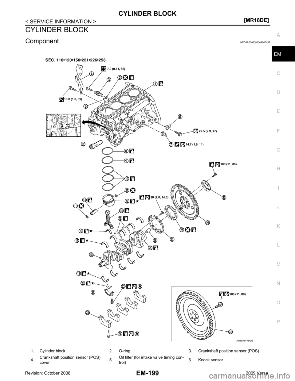
1. Cylinder block 2. O-ring 3. Crankshaft position sensor (POS)
4. Crankshaft position sensor (POS)
cover 5.Oil filter (for intake valve timing con-
trol) 6. Knock sensor
Page 3147 of 4331

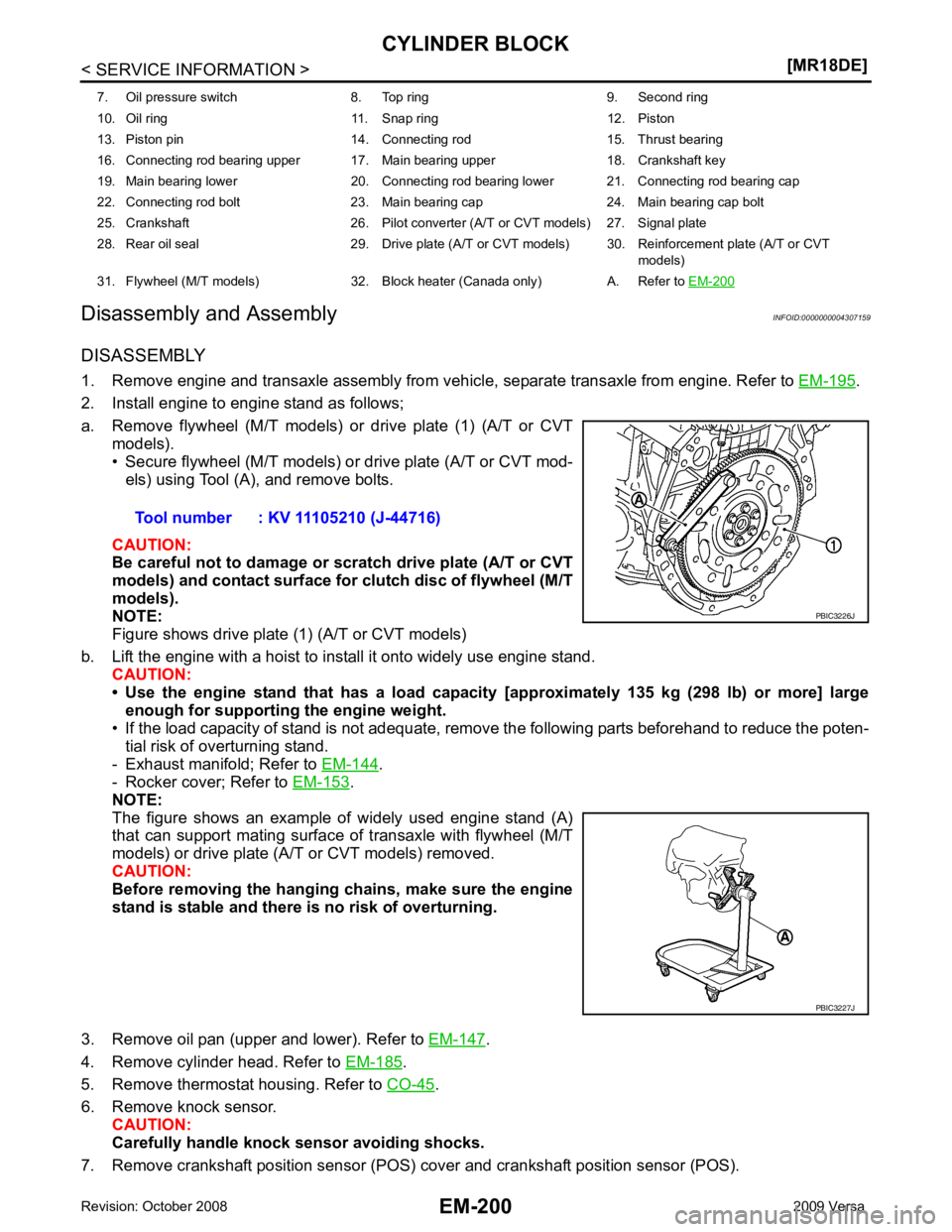
.
2. Install engine to engine stand as follows;
a. Remove flywheel (M/T models) or drive plate (1) (A/T or CVT models).
• Secure flywheel (M/T models) or drive plate (A/T or CVT mod-
els) using Tool (A), and remove bolts.
CAUTION:
Be careful not to damage or scratch drive plate (A/T or CVT
models) and contact surface for clutch disc of flywheel (M/T
models).
NOTE:
Figure shows drive plate (1) (A/T or CVT models)
b. Lift the engine with a hoist to install it onto widely use engine stand. CAUTION:
• Use the engine stand that has a load capacity [approximately 135 kg (298 lb) or more] large
enough for supporting the engine weight.
• If the load capacity of stand is not adequate, remo ve the following parts beforehand to reduce the poten-
tial risk of overturning stand.
- Exhaust manifold; Refer to EM-144 .
- Rocker cover; Refer to EM-153 .
NOTE:
The figure shows an example of widely used engine stand (A)
that can support mating surface of transaxle with flywheel (M/T
models) or drive plate (A/T or CVT models) removed.
CAUTION:
Before removing the hanging chains, make sure the engine
stand is stable and there is no risk of overturning.
3. Remove oil pan (upper and lower). Refer to EM-147 .
4. Remove cylinder head. Refer to EM-185 .
5. Remove thermostat housing. Refer to CO-45 .
6. Remove knock sensor. CAUTION:
Carefully handle knock sensor avoiding shocks.
7. Remove crankshaft position sensor (POS) cover and crankshaft position sensor (POS).
7. Oil pressure switch 8. Top ring 9. Second ring
10. Oil ring 11. Snap ring 12. Piston
13. Piston pin 14. Connecting rod 15. Thrust bearing
16. Connecting rod bearing upper 17. Main bearing upper 18. Crankshaft key
19. Main bearing lower 20. Connecting rod bearing lower 21. Connecting rod bearing cap
22. Connecting rod bolt 23. Main bearing cap 24. Main bearing cap bolt
25. Crankshaft 26. Pilot converter (A/T or CVT models) 27. Signal plate
28. Rear oil seal 29. Drive plate (A/T or CVT models) 30. Reinforcement plate (A/T or CVT models)
31. Flywheel (M/T models) 32. Block heater (Canada only) A. Refer to EM-200 PBIC3227J
Page 3150 of 4331

EM
NP
O
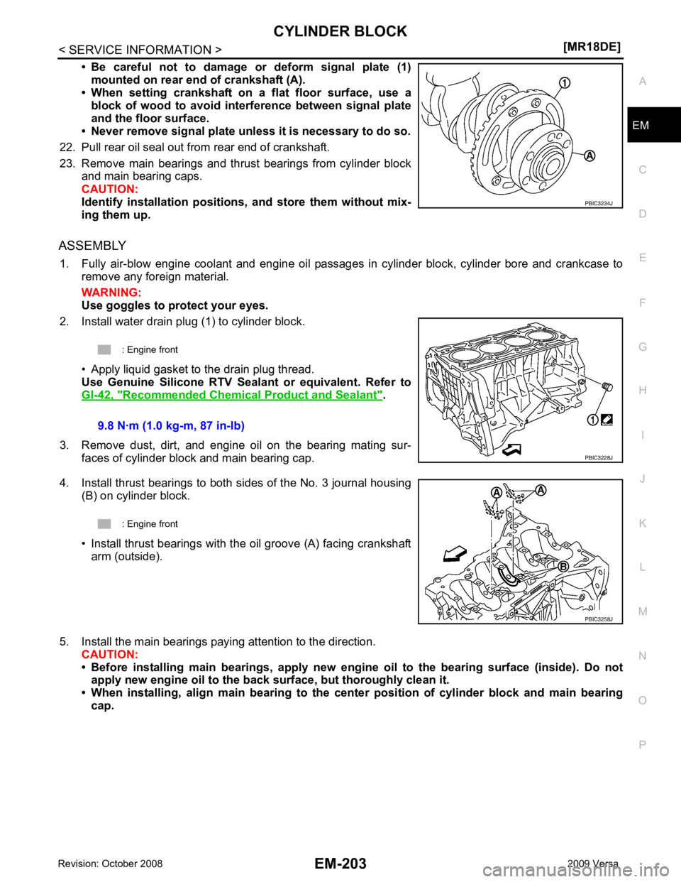
• Be careful not to damage or deform signal plate (1)
mounted on rear end of crankshaft (A).
• When setting crankshaft on a flat floor surface, use a
block of wood to avoid inte rference between signal plate
and the floor surface.
• Never remove signal plate unl ess it is necessary to do so.
22. Pull rear oil seal out from rear end of crankshaft.
23. Remove main bearings and thrust bearings from cylinder block and main bearing caps.
CAUTION:
Identify installation positions, and store them without mix-
ing them up.
ASSEMBLY 1. Fully air-blow engine coolant and engine oil passages in cylinder block, cylinder bore and crankcase to remove any foreign material.
WARNING:
Use goggles to protect your eyes.
2. Install water drain plug (1) to cylinder block.
• Apply liquid gasket to the drain plug thread.
Use Genuine Silicone RTV Seal ant or equivalent. Refer to
GI-42, " Recommended Chemical Product and Sealant " .
3. Remove dust, dirt, and engine oil on the bearing mating sur- faces of cylinder block and main bearing cap.
4. Install thrust bearings to both sides of the No. 3 journal housing (B) on cylinder block.
• Install thrust bearings with the oil groove (A) facing crankshaft arm (outside).
5. Install the main bearings paying attention to the direction. CAUTION:
• Before installing main bearings , apply new engine oil to the bearing surface (inside). Do not
apply new engine oil to the back surface, but thoroughly clean it.
• When installing, align main b earing to the center position of cylinder block and main bearing
cap.
Page 3153 of 4331
![NISSAN TIIDA 2009 Service Repair Manual EM-206< SERVICE INFORMATION >
[MR18DE]
CYLINDER BLOCK
• Position each ring with the gap as shown referring to the pis- ton front mark.
CAUTION:
Never contact the rail end gap under NISSAN TIIDA 2009 Service Repair Manual EM-206< SERVICE INFORMATION >
[MR18DE]
CYLINDER BLOCK
• Position each ring with the gap as shown referring to the pis- ton front mark.
CAUTION:
Never contact the rail end gap under](/manual-img/5/57398/w960_57398-3152.png)
EM-206< SERVICE INFORMATION >
[MR18DE]
CYLINDER BLOCK
• Position each ring with the gap as shown referring to the pis- ton front mark.
CAUTION:
Never contact the rail end gap under the oil ring with the
oil drain cast groove of piston.
• Install second ring with the stamped surface facing upward.
20. Install connecting rod bearing upper (2) and lower (3) to con- necting rod (1) and connecting rod cap (4).
• Install the connecting rod in the dimension shown.
• Make sure that connecting rod bearing oil hole (A) is com- pletely in the inside of connecting rod oil hole chamfered area
(B).
• When installing connecting rod bearings, apply new engine oil to the bearing surface (inside). Do not apply new engine oil to
the back surface, but thoroughly clean it.
NOTE:
• There is no positioning tab.
• Install the connecting rod bearings in the center of connect-
ing rod and connecting rod bearing cap as shown. For ser-
vice operation, the center position can be checked, visually.
21. Install piston and connecting rod assembly to crankshaft. • Position crankshaft pin corresponding to connecting rod to be installed onto the bottom dead center.
• Apply new engine oil sufficiently to the cylinder bore, piston and crankshaft pin.
• Match the cylinder position with the cylinder number (C) on connecting rod to install.
• Install so that front mark (A) on the piston head faces the front of engine.A : Oil ring upper or lower rail gap
B : Front mark
C : Second ring and oil ring spacer gap
D : Top ring gap
E : Stamped mark PBIC3588J
C : Oil hole (connecting rod)
D : Arrow view
: Engine front PBIC4541E
B : Oil hole
D : Big end diameter grade
E : Small end diameter grade
F : Front mark (connecting rod bearing cap) PBIC3587J
Page 3156 of 4331

EM
NP
O
How to Select Piston and Bearing
INFOID:0000000004307160
DESCRIPTION
• The identification grade stamped on each part is the grade for the dimension measured in new condition.
This grade cannot apply to reused parts.
• For reused or repaired parts, measure the dimens ion accurately. Determine the grade by comparing the
measurement with the values of each selection table.
• For details of the measurement method of each part , the reuse standards and the selection method of the
selective fitting parts, follow the applicable procedures.
HOW TO SELECT PISTON
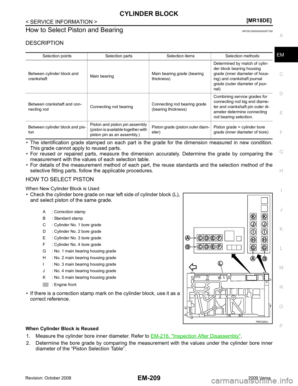
When New Cylinder Block is Used • Check the cylinder bore grade on rear left side of cylinder block (L), and select piston of the same grade.
• If there is a correction stamp mark on the cylinder block, use it as a correct reference.
When Cylinder Block is Reused 1. Measure the cylinder bore inner diameter. Refer to EM-216, " Inspection After Disassembly " .
2. Determine the bore grade by comparing the measur ement with the values under the cylinder bore inner
diameter of the “Piston Selection Table”. Selection points Selection parts Selection items Selection methods
Between cylinder block and
crankshaft Main bearing
Main bearing grade (bearing
thickness) Determined by match of cylin-
der block bearing housing
grade (inner diameter of hous-
ing) and crankshaft journal
grade (outer diameter of jour-
nal)
Between crankshaft and con-
necting rod Connecting rod bearing
Connecting rod bearing grade
(bearing thickness) Combining service grades for
connecting rod big end diame-
ter and crankshaft pin outer di-
ameter determine connecting
rod bearing selection.
Between cylinder block and pis-
ton Piston and piston pin assembly
(piston is available together with
piston pin as an assembly.) Piston grade (piston outer diam-
eter) Piston grade = cylinder bore
grade (inner diameter of bore) A : Correction stamp
B : Standard stamp
C : Cylinder No. 1 bore grade
D : Cylinder No. 2 bore grade
E : Cylinder No. 3 bore grade
F : Cylinder No. 4 bore grade
G : No. 1 main bearing housing grade
H : No. 2 main bearing housing grade
I : No. 3 main bearing housing grade
J : No. 4 main bearing housing grade
K : No. 5 main bearing housing grade
: Engine front