2009 NISSAN TIIDA fuel pump
[x] Cancel search: fuel pumpPage 1305 of 4331
DI
N
O P
COMBINATION METERS
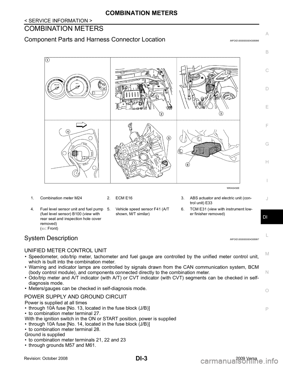
Component Parts and Har ness Connector Location INFOID:0000000004306996
System Description INFOID:0000000004306997
UNIFIED METER CONTROL UNIT • Speedometer, odo/trip meter, tachometer and fuel gauge are controlled by the unified meter control unit,
which is built into the combination meter.
• Warning and indicator lamps are controlled by signal s drawn from the CAN communication system, BCM
(body control module), and components connected directly to the combination meter.
• Odo/trip meter and A/T indicator (with A/T) or CVT i ndicator (with CVT) segments can be checked in self-
diagnosis mode.
• Meters/gauges can be checked in self-diagnosis mode.
POWER SUPPLY AND GROUND CIRCUIT Power is supplied at all times
• through 10A fuse [No. 13, located in the fuse block (J/B)]
• to combination meter terminal 27.
With the ignition switch in the ON or START position, power is supplied
• through 10A fuse [No. 14, located in the fuse block (J/B)]
• to combination meter terminal 28.
Ground is supplied
• to combination meter terminals 21, 22 and 23
• through grounds M57 and M61. 1. Combination meter M24 2. ECM E16 3. ABS actuator and electric unit (con-
trol unit) E33
4. Fuel level sensor unit and fuel pump (fuel level sensor) B100 (view with
rear seat and inspection hole cover
removed)
( ⇐ : Front) 5. Vehicle speed sensor F41 (A/T
shown, M/T similar) 6. TCM E31 (view with
instrument low-
er finisher removed)
Page 1321 of 4331
DI
N
O P
Electrical Component Inspection
INFOID:0000000004307014
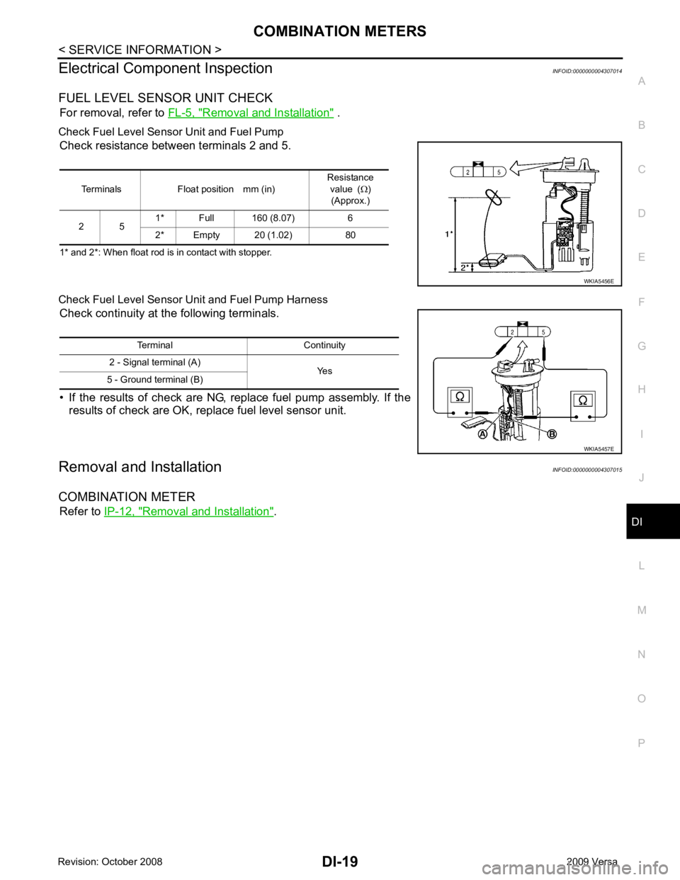
FUEL LEVEL SENSOR UNIT CHECK For removal, refer to FL-5, " Removal and Installation " .
Check Fuel Level Sensor Unit and Fuel Pump Check resistance between terminals 2 and 5.
1* and 2*: When float rod is in contact with stopper.
Check Fuel Level Sensor Unit and Fuel Pump Harness Check continuity at the following terminals.
• If the results of check are NG, replace fuel pump assembly. If the results of check are OK, replace fuel level sensor unit.
Removal and Installation INFOID:0000000004307015
COMBINATION METER Refer to IP-12, " Removal and Installation " .
Terminals Float position mm (in)
Resistance
value ( Ω)
(Approx.)
2 5 1* Full 160 (8.07) 6
2* Empty 20 (1.02) 80
Page 1369 of 4331
EC
A
N
O P
DTC Confirmation Procedure ..............................
..
940
Diagnosis Procedure ........................................... ..941
DTC P2122, P2123 APP SENSOR ................ ..942
Component Description ....................................... ..942
CONSULT-III Refe rence Value in Data Monitor
Mode ................................................................... ..
942
On Board Diagnosis Logic .................................. ..942
DTC Confirmation Procedure .............................. ..942
Wiring Diagram ................................................... ..943
Diagnosis Procedure ........................................... ..944
Component Inspection ........................................ ..946
Removal and Installation .......................................946
DTC P2127, P2128 APP SENSOR ................ ..947
Component Description ....................................... ..947
CONSULT-III Refe rence Value in Data Monitor
Mode ................................................................... ..
947
On Board Diagnosis Logic .................................. ..947
DTC Confirmation Procedure .............................. ..948
Wiring Diagram ................................................... ..949
Diagnosis Procedure ........................................... ..950
Component Inspection ........................................ ..952
Removal and Installation .......................................953
DTC P2135 TP SENSOR ............................... ..954
Component Description ....................................... ..954
CONSULT-III Refe rence Value in Data Monitor
Mode ................................................................... ..
954
On Board Diagnosis Logic .................................. ..954
DTC Confirmation Procedure .............................. ..954
Wiring Diagram ................................................... ..955
Diagnosis Procedure ........................................... ..956
Component Inspection ........................................ ..958
Removal and Installation .......................................958
DTC P2138 APP SENSOR ............................. ..959
Component Description ....................................... ..959
CONSULT-III Refe rence Value in Data Monitor
Mode ................................................................... ..
959
On Board Diagnosis Logic .................................. ..959
DTC Confirmation Procedure .............................. ..960
Wiring Diagram ................................................... ..961
Diagnosis Procedure ........................................... ..962
Component Inspection ........................................ ..965
Removal and Installation .......................................965
DTC P2A00 A/F SENSOR 1 ........................... ..966
Component Description ....................................... ..966
CONSULT-III Refe rence Value in Data Monitor
Mode ................................................................... ..
966
On Board Diagnosis Logic .................................. ..966
DTC Confirmation Procedure .............................. ..966
Wiring Diagram ................................................... ..968
Diagnosis Procedure ........................................... ..969
Removal and Installation .......................................972
ASCD BRAKE SWITCH ................................. ..973
Component Description ....................................... ..973 CONSULT-III Reference Va
lue in Data Monitor
Mode .................................................................... ..
973
Wiring Diagram .................................................... ..974
Diagnosis Procedure ........................................... ..975
Component Inspection ......................................... ..979
ASCD INDICATOR .......................................... 981
Component Description ....................................... ..981
CONSULT-III Reference Va lue in Data Monitor
Mode .................................................................... ..
981
Wiring Diagram .................................................... ..982
Diagnosis Procedure ........................................... ..982
ELECTRICAL LOAD SIGNAL ........................ 984
CONSULT-III Reference Va lue in Data Monitor
Mode .................................................................... ..
984
Diagnosis Procedure ........................................... ..984
FUEL INJECTOR ............................................ 986
Component Description ....................................... ..986
CONSULT-III Reference Va lue in Data Monitor
Mode .................................................................... ..
986
Wiring Diagram .................................................... ..987
Diagnosis Procedure ........................................... ..988
Component Inspection ......................................... ..990
Removal and Installation ..................................... ..990
FUEL PUMP .................................................... 991
Description ........................................................... ..991
CONSULT-III Reference Va lue in Data Monitor
Mode .................................................................... ..
991
Wiring Diagram .................................................... ..992
Diagnosis Procedure ........................................... ..993
Component Inspection ......................................... ..995
Removal and Installation ..................................... ..995
IGNITION SIGNAL .......................................... 996
Component Description ....................................... ..996
Wiring Diagram .................................................... ..997
Diagnosis Procedure ........................................... 1000
Component Inspection ......................................... 1003
Removal and Installation ..................................... 1004
REFRIGERANT PRESSURE SENSOR ......... 1005
Component Description ....................................... 1005
Wiring Diagram .................................................... 1006
Diagnosis Procedure ........................................... 1007
Removal and Installation ..................................... 1009
MIL AND DATA LINK CONNECTOR ............ 1010
Wiring Diagram .................................................... 1010
SERVICE DATA AND SPECIFICATIONS
(SDS) .............................................................. 1012
Fuel Pressure ...................................................... 1012
Idle Speed and Ignition Timing ............................ 1012
Calculated Load Value ........................................ 1012
Mass Air Flow Sensor .......................................... 1012
Intake Air Temperature Sensor ........................... 1012
Engine Coolant Temperature Sensor .................. 1012
Air Fuel Ratio (A/F) Sensor 1 Heater ................... 1013
Page 1377 of 4331
EC
A
N
O P
SERVICE DATA AND SPECIFICATIONS
(SDS) .............................................................. 1534
Fuel Pressure ...................................................... 1534
Idle Speed and Ignition Timing ............................ 1534
Calculated Load Value ........................................ 1534
Mass Air Flow Sensor ......................................... 1534
Intake Air Temperature Sensor ........................... 1534
Engine Coolant Temperature Sensor .................. 1534Air Fuel Ratio (A/F) Sensor 1 Heater ...................
1535
Heated Oxygen sensor 2 Heater ......................... 1535
Crankshaft Position Sensor (POS) ...................... 1535
Camshaft Position Sensor (PHASE) ................... 1535
Throttle Control Motor .......................................... 1535
Fuel Injector ......................................................... 1535
Fuel Pump ........................................................... 1535
Page 1397 of 4331
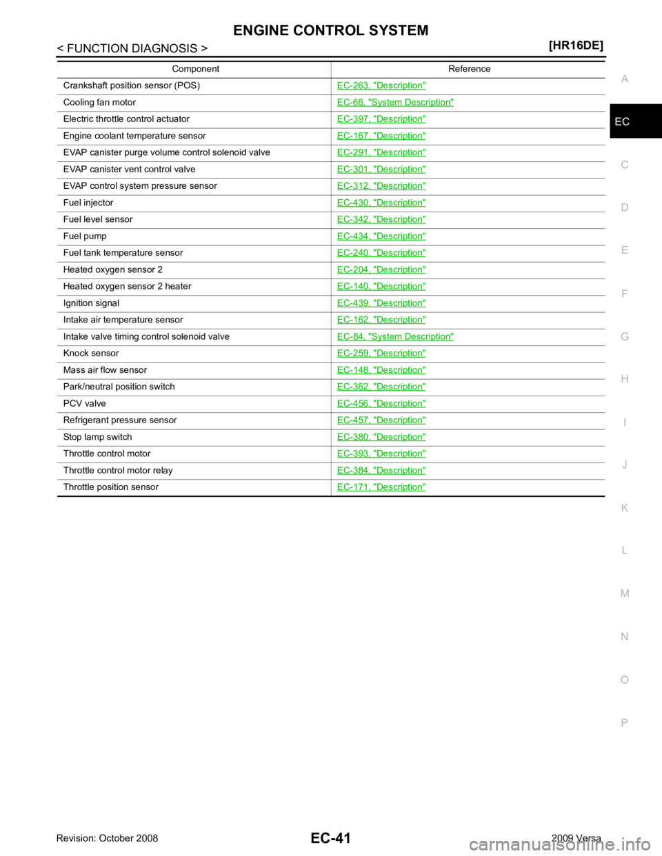
EC
NP
O
Crankshaft position sensor (POS)
EC-263, " Description "
Cooling fan motor
EC-66, " System Description "
Electric throttle control actuator
EC-397, " Description "
Engine coolant temperature sensor
EC-167, " Description "
EVAP canister purge volume control solenoid valve
EC-291, " Description "
EVAP canister vent control valve
EC-301, " Description "
EVAP control system pressure sensor
EC-312, " Description "
Fuel injector
EC-430, " Description "
Fuel level sensor
EC-342, " Description "
Fuel pump
EC-434, " Description "
Fuel tank temperature sensor
EC-240, " Description "
Heated oxygen sensor 2
EC-204, " Description "
Heated oxygen sensor 2 heater
EC-140, " Description "
Ignition signal
EC-439, " Description "
Intake air temperature sensor
EC-162, " Description "
Intake valve timing control solenoid valve
EC-84, " System Description "
Knock sensor
EC-259, " Description "
Mass air flow sensor
EC-148, " Description "
Park/neutral position switch
EC-362, " Description "
PCV valve
EC-456, " Description "
Refrigerant pressure sensor
EC-457, " Description "
Stop lamp switch
EC-380, " Description "
Throttle control motor
EC-393, " Description "
Throttle control motor relay
EC-384, " Description "
Throttle position sensor
EC-171, " Description "Component Reference
Page 1403 of 4331
![NISSAN TIIDA 2009 Service Repair Manual MULTIPORT FUEL INJECTION SYSTEM
EC-47
< FUNCTION DIAGNOSIS >
[HR16DE] C
D E
F
G H
I
J
K L
M A EC
NP
O
1. ECM harness connectors 2. ECM 3. IPDM E/R
4. Fuel pump fuse (15A) 5. Intake valve timing contro NISSAN TIIDA 2009 Service Repair Manual MULTIPORT FUEL INJECTION SYSTEM
EC-47
< FUNCTION DIAGNOSIS >
[HR16DE] C
D E
F
G H
I
J
K L
M A EC
NP
O
1. ECM harness connectors 2. ECM 3. IPDM E/R
4. Fuel pump fuse (15A) 5. Intake valve timing contro](/manual-img/5/57398/w960_57398-1402.png)
MULTIPORT FUEL INJECTION SYSTEM
EC-47
< FUNCTION DIAGNOSIS >
[HR16DE] C
D E
F
G H
I
J
K L
M A EC
NP
O
1. ECM harness connectors 2. ECM 3. IPDM E/R
4. Fuel pump fuse (15A) 5. Intake valve timing control solenoid valve6. Knock sensor
7. Refrigerant pressure sensor 8. PCV valve Vehicle front PBIB2941E
Page 1405 of 4331
![NISSAN TIIDA 2009 Service Repair Manual MULTIPORT FUEL INJECTION SYSTEM
EC-49
< FUNCTION DIAGNOSIS >
[HR16DE] C
D E
F
G H
I
J
K L
M A EC
NP
O
Component Description INFOID:0000000004780013
1. Cooling fan motor harness connec-
tor 2. Cranksha NISSAN TIIDA 2009 Service Repair Manual MULTIPORT FUEL INJECTION SYSTEM
EC-49
< FUNCTION DIAGNOSIS >
[HR16DE] C
D E
F
G H
I
J
K L
M A EC
NP
O
Component Description INFOID:0000000004780013
1. Cooling fan motor harness connec-
tor 2. Cranksha](/manual-img/5/57398/w960_57398-1404.png)
MULTIPORT FUEL INJECTION SYSTEM
EC-49
< FUNCTION DIAGNOSIS >
[HR16DE] C
D E
F
G H
I
J
K L
M A EC
NP
O
Component Description INFOID:0000000004780013
1. Cooling fan motor harness connec-
tor 2. Crankshaft position sensor 3. Stop lamp switch
4. Brake pedal 5. Accelerator pedal position sensor harness connector6. Accelerator pedal position sensor
7. Accelerator pedal 8. Fuel level sensor unit and fuel pump harness connector (view with in-
spection hole cover removed) 9. Fuel pressure regulator
10. Fuel pump AWBIA0044ZZ
Component Reference
A/F sensor 1 EC-182, " Description "
Accelerator pedal position sensor
EC-399, " Description "
Camshaft position sensor (PHASE)
EC-268, " Description "
Crankshaft position sensor (POS)
EC-263, " Description "
Page 1410 of 4331
![NISSAN TIIDA 2009 Service Repair Manual EC-54< FUNCTION DIAGNOSIS >
[HR16DE]
ELECTRIC IGNITION SYSTEM
1. ECM harness connectors 2. ECM 3. IPDM E/R
4. Fuel pump fuse (15A) 5. Intake valve timing control solenoid valve6. Knock sensor
7. Refr NISSAN TIIDA 2009 Service Repair Manual EC-54< FUNCTION DIAGNOSIS >
[HR16DE]
ELECTRIC IGNITION SYSTEM
1. ECM harness connectors 2. ECM 3. IPDM E/R
4. Fuel pump fuse (15A) 5. Intake valve timing control solenoid valve6. Knock sensor
7. Refr](/manual-img/5/57398/w960_57398-1409.png)
EC-54< FUNCTION DIAGNOSIS >
[HR16DE]
ELECTRIC IGNITION SYSTEM
1. ECM harness connectors 2. ECM 3. IPDM E/R
4. Fuel pump fuse (15A) 5. Intake valve timing control solenoid valve6. Knock sensor
7. Refrigerant pressure sensor 8. PCV valve Vehicle front PBIB2941E