2009 NISSAN TIIDA lock
[x] Cancel search: lockPage 2926 of 4331

EI
N
O P
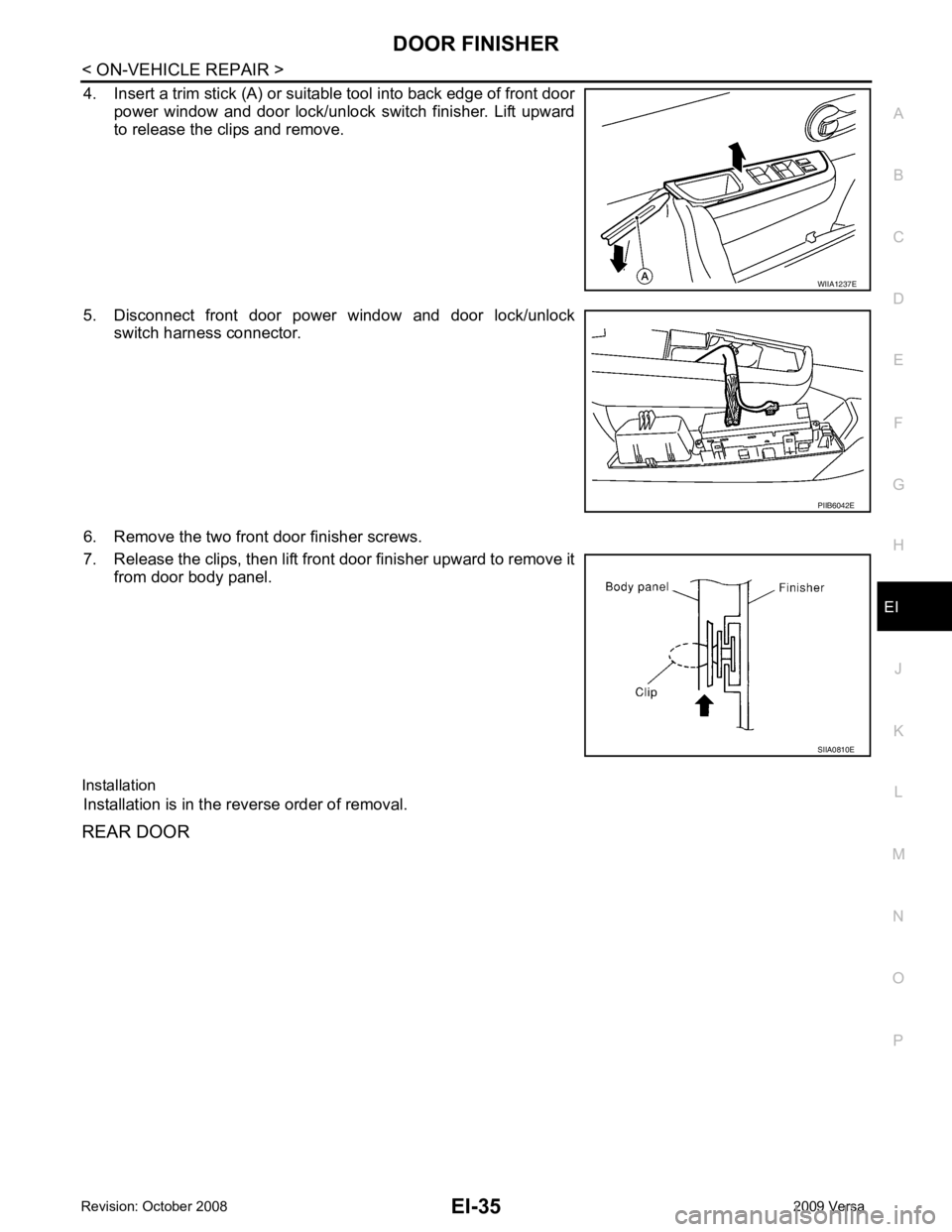
4. Insert a trim stick (A) or suitable tool into back edge of front door
power window and door lock/unlock switch finisher. Lift upward
to release the clips and remove.
5. Disconnect front door power window and door lock/unlock switch harness connector.
6. Remove the two front door finisher screws.
7. Release the clips, then lift front door finisher upward to remove it from door body panel.
Installation Installation is in the reverse order of removal.
REAR DOOR PIIB6042E
Page 2937 of 4331

.
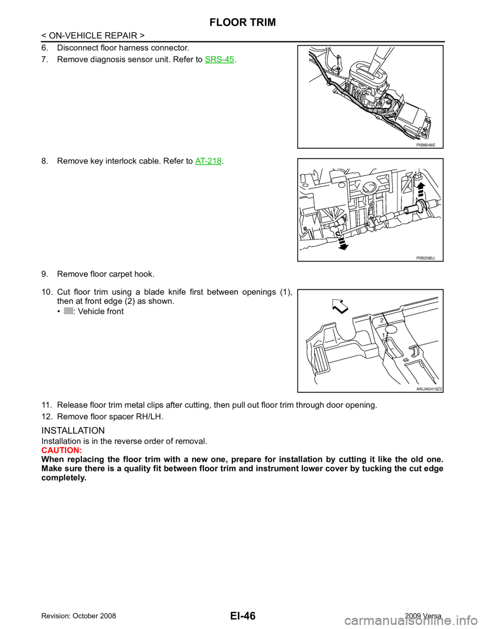
8. Remove key interlock cable. Refer to AT-218 .
9. Remove floor carpet hook.
10. Cut floor trim using a blade knife first between openings (1), then at front edge (2) as shown.
• : Vehicle front
11. Release floor trim metal clips after cutting, then pull out floor trim through door opening.
12. Remove floor spacer RH/LH.
INSTALLATION
Installation is in the reverse order of removal.
CAUTION:
When replacing the floor trim with a new one, prepar e for installation by cutting it like the old one.
Make sure there is a quality fit between floor trim and instrument lower cover by tucking the cut edge
completely. PIIB2580J
Page 2940 of 4331

EI
N
O P
Removal and Installation - Hatchback
INFOID:0000000004307236
REMOVAL 1. Disconnect the negative and positive battery term inals, then wait at least three minutes.
2. Remove front seat assembly RH/LH. Refer to SE-12, " Removal and Installation " .
3. Remove rear seat cushion and rear seatback. Refer to SE-16, " Removal and Installation " .
4. Remove front seat belt shoulder anchor RH/LH. Refer to SB-4, " Removal and Installation of Front Seat
Belt " .
5. Remove center console body assembly. Refer to IP-11 .
6. Remove front pillar garnish RH/LH. Refer to EI-40, " Removal and Installation " .
7. Remove antenna feeder cable clip, then disconnect antenna feeder cable connector.
8. Remove front and rear kicking plate inner RH/LH, cent er pillar lower garnish, center pillar upper garnish,
front and rear body side welt RH/LH. Refer to EI-40, " Removal and Installation " .
WARNING:
Do not reuse center pillar upper garnish if removed.
9. Remove back door weatherstrip. Refer to EI-38 .
10. Release the clips using a suitable tool, then remove the front and rear assist grips.
11. Remove the sunvisor caps and screws, then remove sunvisor RH/LH. 1. Headlining 2. Assist grip 3. Room lamp
4. Sunvisor 5. Cap 6. Sunvisor holder
7. Map lamp assembly (if equipped) 8. Antenna feeder cable 9. Roof console assembly (if equipped)
10. Roof plate (if equipped) 11. Dual lock fastener 12. Insulator
13. Room lamp harness 14. Cover A. With sunroof
B. Without sunroof Clip C103 ⇐Vehicle front PIIB2584J
Page 2943 of 4331

EI-52< ON-VEHICLE REPAIR >
HEADLINING
14. Disconnect antenna feeder cable near rear pillar finisher LH.
15. Disengage the dual lock fastener on the backside of headlining. • Insert a suitable tool into the edge of dual lock fastener, then move the tool side to side horizontally to
release it.
CAUTION:
Excessive up and down force may cause roof panel damage.
16. Position the headlining so the front edge goes through the open- ing of the right side front door.
17. Position the headlining so the rear edge goes through the open- ing of the left rear door, then remove headlining.
CAUTION:
• 2 technicians should be used to avoid damage when remov-
ing or replacing headlining.
• During headlining removal and installation, cover the center
console finisher upper surface to prevent damage.
• Set A/T or CVT shift lever to the D position, and make a space to remove front end of headlining right side.
• Do not bend headlining when removing.
INSTALLATION
Installation is in the reverse order of removal.
CAUTION:
Avoid headlining damage when installing by inserting rear clips first during assembly. PIIB2586J
PIIB6049E
Page 2950 of 4331

EM
A
N
O P
OIL PAN .........................................................
..147
Component .......................................................... ..147
Removal and Installation .......................................147
IGNITION COIL, SPARK PLUG AND ROCK-
ER COVER ..................................................... ..153
Component .......................................................... ..153
Removal and Installation .......................................153
FUEL INJECTOR AND FUEL TUBE ............. ..156
Component .......................................................... ..156
Removal and Installation .......................................156
TIMING CHAIN ............................................... ..160
Component .......................................................... ..160
Removal and Installation .......................................161
CAMSHAFT .................................................... ..170
Component .......................................................... ..170
Removal and Installation .......................................170
Valve Clearance .................................................. ..178
OIL SEAL ....................................................... ..182
Removal and Installation of Valve Oil Seal ......... ..182
Removal and Installation of Front Oil Seal .......... ..182 Removal and Installation of
Rear Oil Seal .............183
CYLINDER HEAD ........................................... 185
On-Vehicle Service .............................................. ..185
Component .......................................................... ..186
Removal and Installation ..................................... ..186
Component .......................................................... ..188
Disassembly and Assembly ................................. ..189
Inspection After Disassembly .............................. ..190
ENGINE ASSEMBL Y ...................................... 195
Component .......................................................... ..195
Removal and Installation ..................................... ..195
CYLINDER BLOCK ......................................... 199
Component .......................................................... ..199
Disassembly and Assembly ................................. ..200
How to Select Piston a nd Bearing ....................... ..209
Inspection After Disassembly .............................. ..216
SERVICE DATA AND SPECIFICATIONS
(SDS) ............................................................... 227
Standard and Limit .............................................. ..227
Page 2952 of 4331
![NISSAN TIIDA 2009 Service Repair Manual PRECAUTIONS
EM-5
< PRECAUTION >
[HR16DE] C
D E
F
G H
I
J
K L
M A EM
NP
O
5. When the repair work is completed, return the ignition switch to the
″LOCK ″ position before connecting
t NISSAN TIIDA 2009 Service Repair Manual PRECAUTIONS
EM-5
< PRECAUTION >
[HR16DE] C
D E
F
G H
I
J
K L
M A EM
NP
O
5. When the repair work is completed, return the ignition switch to the
″LOCK ″ position before connecting
t](/manual-img/5/57398/w960_57398-2951.png)
PRECAUTIONS
EM-5
< PRECAUTION >
[HR16DE] C
D E
F
G H
I
J
K L
M A EM
NP
O
5. When the repair work is completed, return the ignition switch to the
″LOCK ″ position before connecting
the battery cables. (At this time, the steering lock mechanism will engage.)
6. Perform a self-diagnosis check of al l control units using CONSULT-III.
Precaution for Procedur e without Cowl Top Cover INFOID:0000000004784258
When performing the procedure after removing cowl top cover, cover
the lower end of windshield.
Precaution for Drain Coolant INFOID:0000000004784260
• Drain coolant when engine is cooled.
Precaution for Disco nnecting Fuel Piping INFOID:0000000004784261
• Before starting work, make sure no fire or spark producing items are in the work area.
• Release fuel pressure before disassembly.
• After disconnecting pipes, plug openings to stop fuel leakage.
Precaution for Removal and Disassembly INFOID:0000000004784262
• When instructed to use special service tools, use the spec ified tools. Always be careful to work safely, avoid
forceful or uninstructed operations.
• Exercise maximum care to avoid damage to mating or sliding surfaces.
• Cover openings of engine system with tape or the equiva lent, if necessary, to seal out foreign materials.
• Mark and arrange disassembly parts in an organized way for easy troubleshooting and assembly.
• When loosening nuts and bolts, as a basic rule, start with the one furthest outside, then the one diagonally opposite, and so on. If the order of loosening is specif ied, do exactly as specified. Power tools may be used
where noted in the step.
Precaution for Inspection, Repair and Replacement INFOID:0000000004784263
• Before repairing or replacing, thoroughly inspect parts. Inspect new replacement parts in the same way, and
replace if necessary.
Precaution for Assembly and Installation INFOID:0000000004784264
• Use torque wrench to tighten bolts or nuts to specification.
• When tightening nuts and bolts, as a basic rule, equally tighten in several different steps starting with the ones in center, then ones on inside and outside diagonally in this order. If the order of tightening is specified,
do exactly as specified.
• Replace with new gasket, packing, oil seal or O-ring.
• Thoroughly wash, clean, and air-blow each part. Carefully check oil or coolant passages for any restriction
and blockage.
• Avoid damaging sliding or mating surfaces. Completely remove foreign materials such as cloth lint or dust. Before assembly, oil sliding surfaces well.
• Release air within route after draining coolant.
• Before starting engine, apply fuel pressure to fuel lines with turning ignition switch ON (with engine stopped). Then make sure that there are no leaks at fuel line connections.
• After repairing, start engine and increase engine speed to check coolant, fuel, oil, and exhaust systems for leakage. PIIB3706J
Page 2960 of 4331

EM
NP
O
Use the Chart Below to Help You
Find the Cause of the Symptom INFOID:0000000004784256
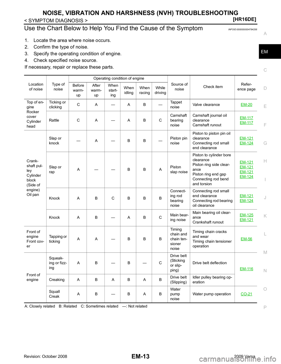
1. Locate the area where noise occurs.
2. Confirm the type of noise.
3. Specify the operating condition of engine.
4. Check specified noise source.
If necessary, repair or replace these parts.
A: Closely related B: Related C: Sometimes related —: Not related Location
of noise Type of
noise Operating condition of engine
Source of noise Check item Refer-
ence page
Before
warm- up After
warm- up When
start- ing When
idling When
racing While
driving
Top of en-
gine
Rocker
cover
Cylinder
head Ticking or
clicking C A — A B — Tappet
noise Valve clearance
EM-20 Rattle C A — A B C
Camshaft
bearing
noise Camshaft journal oil
clearance
Camshaft runout EM-117 EM-117
Crank-
shaft pul-
ley
Cylinder
block
(Side of
engine)
Oil pan Slap or
knock — A — B B —
Piston pin
noise Piston to piston pin oil
clearance
Connecting rod small
end clearance EM-121 EM-124
Slap or
rap A — — B B A
Piston
slap noise Piston to cylinder bore
clearance
Piston ring side clear-
ance
Piston ring end gap
Connecting rod bend
and torsion EM-121 EM-121
EM-121
EM-124
Knock A B C B B B
Connect-
ing rod
bearing
noise Connecting rod small
end clearance
Connecting rod bearing
oil clearance EM-121 EM-124
Knock A B — A B C
Main bear-
ing noise Main bearing oil clear-
ance
Crankshaft runout EM-125 EM-121
Front of
engine
Front cov-
er Tapping or
ticking A A — B B B Timing
chain and
chain ten-
sioner
noise Timing chain cracks
and wear
Timing chain tensioner
operation EM-56Front of
engine Squeak-
ing or fizz-
ing A B — B — C Drive belt
(Sticking
or slip-
ping) Drive belt deflection
EM-116 Creaking A B A B A B
Drive belt
(Slipping) Idler pulley bearing op-
eration
Squall
Creak A B — B A B Water
pump
noise Water pump operation
CO-21
Page 2962 of 4331
![NISSAN TIIDA 2009 Service Repair Manual DRIVE BELTS
EM-15
< ON-VEHICLE MAINTENANCE >
[HR16DE] C
D E
F
G H
I
J
K L
M A EM
NP
O
• When the lock nut is loosened excessively, the idle
r pulley tilts and the correct tension adju NISSAN TIIDA 2009 Service Repair Manual DRIVE BELTS
EM-15
< ON-VEHICLE MAINTENANCE >
[HR16DE] C
D E
F
G H
I
J
K L
M A EM
NP
O
• When the lock nut is loosened excessively, the idle
r pulley tilts and the correct tension adju](/manual-img/5/57398/w960_57398-2961.png)
DRIVE BELTS
EM-15
< ON-VEHICLE MAINTENANCE >
[HR16DE] C
D E
F
G H
I
J
K L
M A EM
NP
O
• When the lock nut is loosened excessively, the idle
r pulley tilts and the correct tension adjust-
ment cannot be performed. Never loo sen it excessively (more than 45 degrees).
• Put a matching mark on the lock nut, and check turning angle with a protractor. Never visually
check the tightening angle.
2. Adjust the belt tension by turning the adjusting bolt. CAUTION:
• When checking immediately after in stallation, first adjust it to the specified value. Then, after
turning crankshaft two turns or more, re-adjust to the specified value to avoid variation in deflec-
tion between pulleys.
• When the tension adjustment is performed, the lo ck nut should be in the condition at step“2”. If
the tension adjustment is performed when the lo ck nut is loosened more than the standard, the
idler pulley tilts and the correct tens ion adjustment cannot be performed.
3. Tighten the idler pulley lock nut.
Removal and Installation INFOID:0000000004784271
REMOVAL 1. Loosen the idler pulley lock nut (A), and then adjust the belt ten- sion by turning the adjusting bolt (B).
2. Remove drive belt.
INSTALLATION 1. Pull the idler pulley in the loosening direction, and then tempo- rarily tighten the idler pulley lock nut (A) to the following torque.
NOTE:
Do not move the lock nut from the tightened position. Proceed to step “2”.
2. Install the drive belt to each pulley. CAUTION:
• Make sure that there is no oil, grease, or coolant, etc. in pulley grooves.
• Make sure that the belt is securely inside the groove on each pulley.
3. Adjust drive belt tension by turning the adjusting bolt. Refer to EM-14, " Tension Adjustment " .
CAUTION: Idler pulley lock nut : 34.8 N·m (3.5 kg-m, 26 ft-lb)
1 : Generator
2 : Water pump
3 : Crankshaft pulley
4 : A/C compressor (with A/C models)
: Idler pulley (without A/C models)
5 : Idler pulley
6 : Drive belt PBIC3643E
1 : Generator
2 : Water pump
3 : Crankshaft pulley
4 : A/C compressor (with A/C models)
: Idler pulley (without A/C models)
5 : Idler pulley
6 : Drive belt
B : Adjusting bolt
Idler pulley lock nut : 4.4 N·m (0.45 kg-m, 39 in-lb)
(temporary tightening) PBIC3643E