2009 NISSAN TIIDA diagnostic menu
[x] Cancel search: diagnostic menuPage 88 of 4331

AT
N
O P
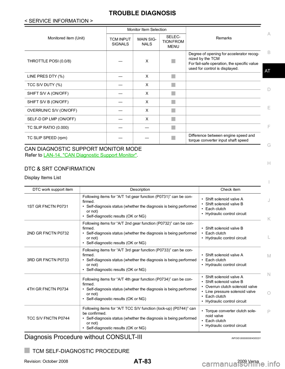
CAN DIAGNOSTIC SUPPORT MONITOR MODE
Refer to LAN-14, " CAN Diagnostic Support Monitor " .
DTC & SRT CONFIRMATION
Display Items List
Diagnosis Procedure without CONSULT-III INFOID:0000000004305331
TCM SELF-DIAGNOSTIC PROCEDURE
THROTTLE POSI (0.0/8) — X
Degree of opening for accelerator recog-
nized by the TCM
For fail-safe operation, the specific value
used for control is displayed.
LINE PRES DTY (%) — X
TCC S/V DUTY (%) — X
SHIFT S/V A (ON/OFF) — X
SHIFT S/V B (ON/OFF) — X
OVERRUN/C S/V (ON/OFF) — X
SELF-D DP LMP (ON/OFF) — X
TC SLIP RATIO (0.000) — —
TC SLIP SPEED (rpm) — — Difference between engine speed and
torque converter input shaft speed
Monitored item (Unit)
Monitor Item Selection
Remarks
TCM INPUT
SIGNALS MAIN SIG-
NALS SELEC-
TION FROM
MENU DTC work support item Description Check item
1ST GR FNCTN P0731 Following items for “A/T 1st gear function (P0731)” can be con-
firmed.
• Self-diagnosis status (whether the diagnosis is being performed or not)
• Self-diagnostic results (OK or NG) • Shift solenoid valve A
• Shift solenoid valve B
• Each clutch
• Hydraulic control circuit
2ND GR FNCTN P0732 Following items for “A/T 2nd gear function (P0732)” can be con-
firmed.
• Self-diagnosis status (whether the diagnosis is being performed or not)
• Self-diagnostic results (OK or NG) • Shift solenoid valve B
• Each clutch
• Hydraulic control circuit
3RD GR FNCTN P0733 Following items for “A/T 3rd gear function (P0733)” can be con-
firmed.
• Self-diagnosis status (whether the diagnosis is being performed
or not)
• Self-diagnostic results (OK or NG) • Shift solenoid valve A
• Each clutch
• Hydraulic control circuit
4TH GR FNCTN P0734 Following items for “A/T 4th gear function (P0734)” can be con-
firmed.
• Self-diagnosis status (whether the diagnosis is being performed or not)
• Self-diagnostic results (OK or NG) • Shift solenoid valve A
• Shift solenoid valve B
• Overrun clutch solenoid valve
• Line pressure solenoid valve
• Each clutch
• Hydraulic control circuit
TCC S/V FNCTN P0744 Following items for “A/T TCC S/V
function (lock-up) (P0744)” can
be confirmed.
• Self-diagnosis status (whether the diagnosis is being performed or not)
• Self-diagnostic results (OK or NG) • Torque converter clutch sole-
noid valve
• Each clutch
• Hydraulic control circuit
Page 861 of 4331

BRC
N
O P
Note 1: If wheel sens
or 2 for each wheel is indicated, check ABS actuator and electric unit (control unit) power supply voltage in addition
to wheel sensor circuit check.
Note 2: If multiple malfunctions are detected including CAN communication line [U1000], perform diagnosis for CAN communication line
first.
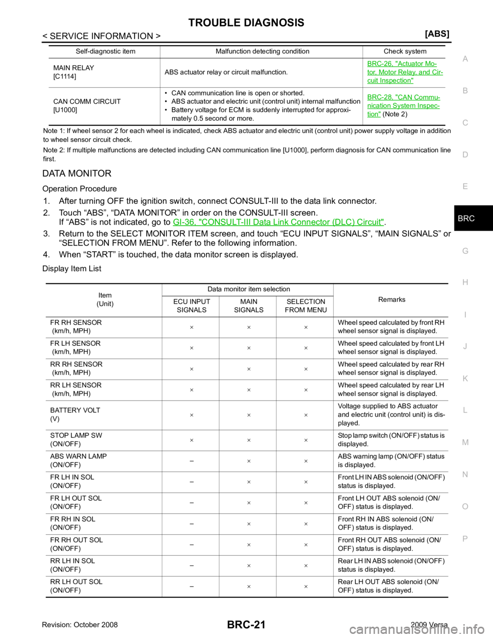
DATA MONITOR
Operation Procedure 1. After turning OFF the ignition switch, c onnect CONSULT-III to the data link connector.
2. Touch “ABS”, “DATA MONITOR” in order on the CONSULT-III screen. If “ABS” is not indicated, go to GI-36, " CONSULT-III Data Link Connector (DLC) Circuit " .
3. Return to the SELECT MONITOR ITEM screen, and touch “ECU INPUT SIGNALS”, “MAIN SIGNALS” or
“SELECTION FROM MENU”. Refer to the following information.
4. When “START” is touched, the data monitor screen is displayed.
Display Item List MAIN RELAY
[C1114] ABS actuator relay or circuit malfunction. BRC-26, " Actuator Mo-
tor, Motor Relay, and Cir-
cuit Inspection "
CAN COMM CIRCUIT
[U1000] • CAN communication line is open or shorted.
• ABS actuator and electric unit (control unit) internal malfunction
• Battery voltage for ECM is suddenly interrupted for approxi-
mately 0.5 second or more. BRC-28, " CAN Commu-
nication System Inspec-
tion " (Note 2)
Self-diagnostic item Malfunction detecting condition Check system Item
(Unit) Data monitor item selection
Remarks
ECU INPUT
SIGNALS MAIN
SIGNALS SELECTION
FROM MENU
FR RH SENSOR
(km/h, MPH) × × × Wheel speed calculated by front RH
wheel sensor signal is displayed.
FR LH SENSOR
(km/h, MPH) × × ×
Wheel speed calculated by front LH
wheel sensor signal is displayed.
RR RH SENSOR
(km/h, MPH) × × × Wheel speed calculated by rear RH
wheel sensor signal is displayed.
RR LH SENSOR
(km/h, MPH) × × × Wheel speed calculated by rear LH
wheel sensor signal is displayed.
BATTERY VOLT
(V) × × × Voltage supplied to ABS actuator
and electric unit (control unit) is dis-
played.
STOP LAMP SW
(ON/OFF) × × × Stop lamp switch (ON/OFF) status is
displayed.
ABS WARN LAMP
(ON/OFF) –
× × ABS warning lamp (ON/OFF) status
is displayed.
FR LH IN SOL
(ON/OFF) –
× × Front LH IN ABS solenoid (ON/OFF)
status is displayed.
FR LH OUT SOL
(ON/OFF) –
× × Front LH OUT ABS solenoid (ON/
OFF) status is displayed.
FR RH IN SOL
(ON/OFF) –
× × Front RH IN ABS solenoid (ON/
OFF) status is displayed.
FR RH OUT SOL
(ON/OFF) –
× × Front RH OUT ABS solenoid (ON/
OFF) status is displayed.
RR LH IN SOL
(ON/OFF) –
× × Rear LH IN ABS solenoid (ON/OFF)
status is displayed.
RR LH OUT SOL
(ON/OFF) –
× × Rear LH OUT ABS solenoid (ON/
OFF) status is displayed.
Page 1003 of 4331

CVT
N
O P
Diagnosis Procedure
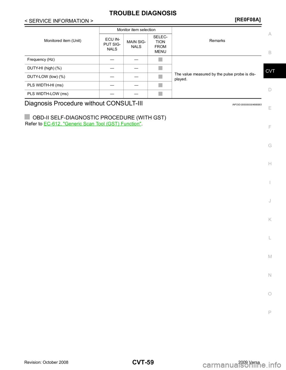
without CONSULT-III INFOID:0000000004666893
OBD-II SELF-DIAGNOSTIC PROCEDURE (WITH GST)
Refer to EC-612, " Generic Scan Tool (GST) Function " .
Frequency (Hz) — —
The value measured by the pulse probe is dis-
played.
DUTY-HI (high) (%) — —
DUTY-LOW (low) (%) — —
PLS WIDTH-HI (ms) — —
PLS WIDTH-LOW (ms) — — Monitored item (Unit)
Monitor item selection
Remarks
ECU IN-
PUT SIG- NALS MAIN SIG-
NALS SELEC-
TION
FROM
MENU
Page 1181 of 4331

CVT
N
O P
Diagnosis Procedure
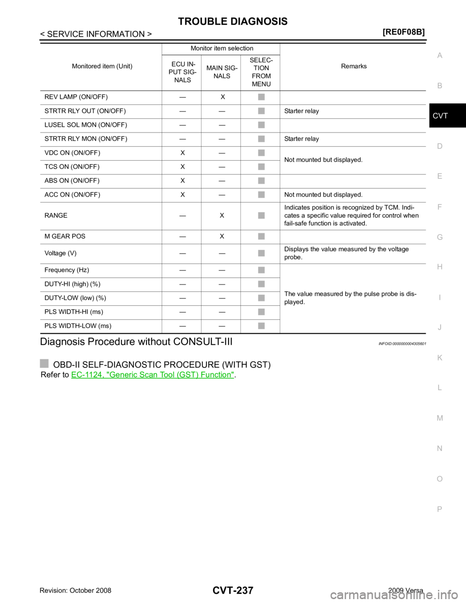
without CONSULT-III INFOID:0000000004305601
OBD-II SELF-DIAGNOSTIC PROCEDURE (WITH GST)
Refer to EC-1124, " Generic Scan Tool (GST) Function " .
REV LAMP (ON/OFF) — X
STRTR RLY OUT (ON/OFF) — — Starter relay
LUSEL SOL MON (ON/OFF) — —
STRTR RLY MON (ON/OFF) — — Starter relay
VDC ON (ON/OFF) X — Not mounted but displayed.
TCS ON (ON/OFF) X —
ABS ON (ON/OFF) X —
ACC ON (ON/OFF) X — Not mounted but displayed.
RANGE — X Indicates position is recognized by TCM. Indi-
cates a specific value required for control when
fail-safe function is activated.
M GEAR POS — X
Voltage (V) — — Displays the value measured by the voltage
probe.
Frequency (Hz) — —
The value measured by the pulse probe is dis-
played.
DUTY-HI (high) (%) — —
DUTY-LOW (low) (%) — —
PLS WIDTH-HI (ms) — —
PLS WIDTH-LOW (ms) — — Monitored item (Unit)
Monitor item selection
Remarks
ECU IN-
PUT SIG- NALS MAIN SIG-
NALS SELEC-
TION
FROM
MENU
Page 1349 of 4331
![NISSAN TIIDA 2009 Service Repair Manual DI
N
O P
DATA MONITOR
Display Item List
ACTIVE TEST
Display Item List
SELF-DIAG RESULTS
Display Item List
NOTE:
If “CAN communication [U1000]” is indicated, after prin ting the monitor i NISSAN TIIDA 2009 Service Repair Manual DI
N
O P
DATA MONITOR
Display Item List
ACTIVE TEST
Display Item List
SELF-DIAG RESULTS
Display Item List
NOTE:
If “CAN communication [U1000]” is indicated, after prin ting the monitor i](/manual-img/5/57398/w960_57398-1348.png)
DI
N
O P
DATA MONITOR
Display Item List
ACTIVE TEST
Display Item List
SELF-DIAG RESULTS
Display Item List
NOTE:
If “CAN communication [U1000]” is indicated, after prin ting the monitor item, go to “LAN system”. Refer to
LAN-17, " Trouble Diagnosis Flow Chart " .
Trouble Diagnosis INFOID:0000000004307032
HOW TO PERFORM TROUBLE DIAGNOSIS 1. Confirm the symptom and customer complaint.
2. Understand the outline of system. Refer to DI-42, " System Description " .
3. Perform the preliminary inspection. Refer to "PRELIMINARY INSPECTION".
4. According to symptom c hart, repair or replace the cause of the malfunction. Refer to "SYMPTOM
CHART".
5. Does warning chime system operate normally? If it operates normally, GO TO 6. If not, GO TO 4.
6. Inspection End.
PRELIMINARY INSPECTION BCM diagnostic
test item Diagnostic mode Description
Inspection by part WORK SUPPORT
Supports inspections and adjustments. Commands are transmitted to the BCM for
setting the status suitable for required operation, input/output signals are received
from the BCM and received data is displayed.
DATA MONITOR Displays BCM input/output data in real time. ACTIVE TEST Operation of electrical loads can be checked by sending drive signal to them.
SELF-DIAG RESULTS Displays BCM self-diagnosis results.
CAN DIAG SUPPORT MNTR The result of transmit/receive diagnosis of CAN communication can be read. ECU PART NUMBER BCM part number can be read.CONFIGURATION Performs BCM configuration read/write functions. Monitored item ALL SIGNALS
SELECTION
FROM MENU Contents
IGN ON SW X X Indicates [ON/OFF] condition of ignition switch.
KEY ON SW X X Indicates [ON/OFF] condition of key switch.
DOOR SW-DR X X Indicates [ON/OFF] condition of front door switch LH.
LIGHT SW 1ST X X Indicates [ON/OFF] condition of lighting switch.
BUCKLE SW X X Indicates [ON/OFF] condition of seat belt buckle switch LH. Test item Malfunction is detected when···
IGN KEY WARN ALM This test is able to check key warning chime operation.
LIGHT WARN ALM This test is able to check light warning chime operation.
SEAT BELT WARN TEST This test is able to check seat belt warning chime operation. Display item [Code] Malfunction is detected when...
CAN communication [U1000] Malfunction is detected in CAN communication.
Page 4303 of 4331

WW
N
O P
NOTE: This item is displayed, but cannot be monitored.
ACTIVE TEST
Display Item List
CONSULT-III Function (IPDM E/R) INFOID:0000000004306914
CONSULT-III can display each diagnostic item using the diagnostic test modes shown following.
DATA MONITOR
All Signals, Main Signals, Selection From Menu
NOTE: FR WIPER INT “ON/OFF” Displays “FRONT WIPER INT (ON)/Other
(OFF)” status as judged from wiper switch signal.
FR WASHER SW “ON/OFF” Displays “FRONT WASHER Switch
(ON)/Other (OFF)” status as judged from wiper switch sig-
nal.
INT VOLUME “1 - 7” Displays intermittent operation dial position setting (1 - 7) as judged from wiper switch signal.
FR WIPER STOP “ON/OFF” Displays “Stopped (ON)/Operati ng (OFF)” status as judged from auto-stop signal.
VEHICLE SPEED “km/h” Displays vehicle speed stat us as judged from vehicle speed signal.
RR WIPER ON “ON/OFF” Displays “REAR WIPER (ON)/Other (O FF)” status as judged from wiper switch signal.
RR WIPER INT “ON/OFF” Displays “REAR WIPER INT (ON)/Other (OFF)” status as judged from wiper switch signal.
RR WASHER SW “ON/OFF” Displays “FRONT WASHER Switch
(ON)/Other (OFF)” status as judged from wiper switch sig-
nal.
RR WIPER STOP “ON/OFF” Displays “Stopp ed (ON)/Operating (OFF)” status as judged from auto-stop switch 1.
RR WIPER STP2 “ON/OFF” Displays “Stopp ed (ON)/Operating (OFF)” status as judged from auto-stop switch 2.
H/L WASH SW NOTE
“OFF” —
Monitor item Contents Test item Display on CONSULT-III screen Description
Front wiper LO output FR WIPER (LO) Front LO wiper can be operated by any ON-OFF operation.
Front wiper HI output FR WIPER (HI) Front HI wiper can be operated by any ON-OFF operation.
Front wiper INT output FR WIPER (INT) Front INT wiper can be operated by any ON-OFF operation.
Rear wiper output RR WIPER Rear wiper can be operated by any ON-OFF operation. IPDM E/R diagnostic Mode Description
SELF-DIAG RESULTS Displays IPDM E/R self-diagnosis results.
DATA MONITOR Displays IPDM E/R input/output data in real time.
CAN DIAG SUPPORT MNTR The result of transmit/receive diagnosis of CAN communication can be read. ACTIVE TEST Operation of electrical loads can be checked by sending drive signal to them. ALL SIGNALS Monitors all items.
MAIN SIGNALS Monitor the predetermined item.
SELECTION FROM MENU Selects items and monitors them. Item name
CONSULT-III
screen display Display or unit Monitor item selection
Description
ALL
SIGNALS MAIN
SIGNALS SELECTION
FROM MENU
FR wiper request FR WIP REQ STOP/1LOW/
LOW/HI × × ×
Signal status input from BCM
Wiper auto stop WIP AUTO STOP ACT P/STOP P × × ×Output status of IPDM E/R
Wiper protection WIP PROT OFF/BLOCK × × ×Control status of IPDM E/R