2009 NISSAN TIIDA e control
[x] Cancel search: e controlPage 296 of 4331
AT
N
O P
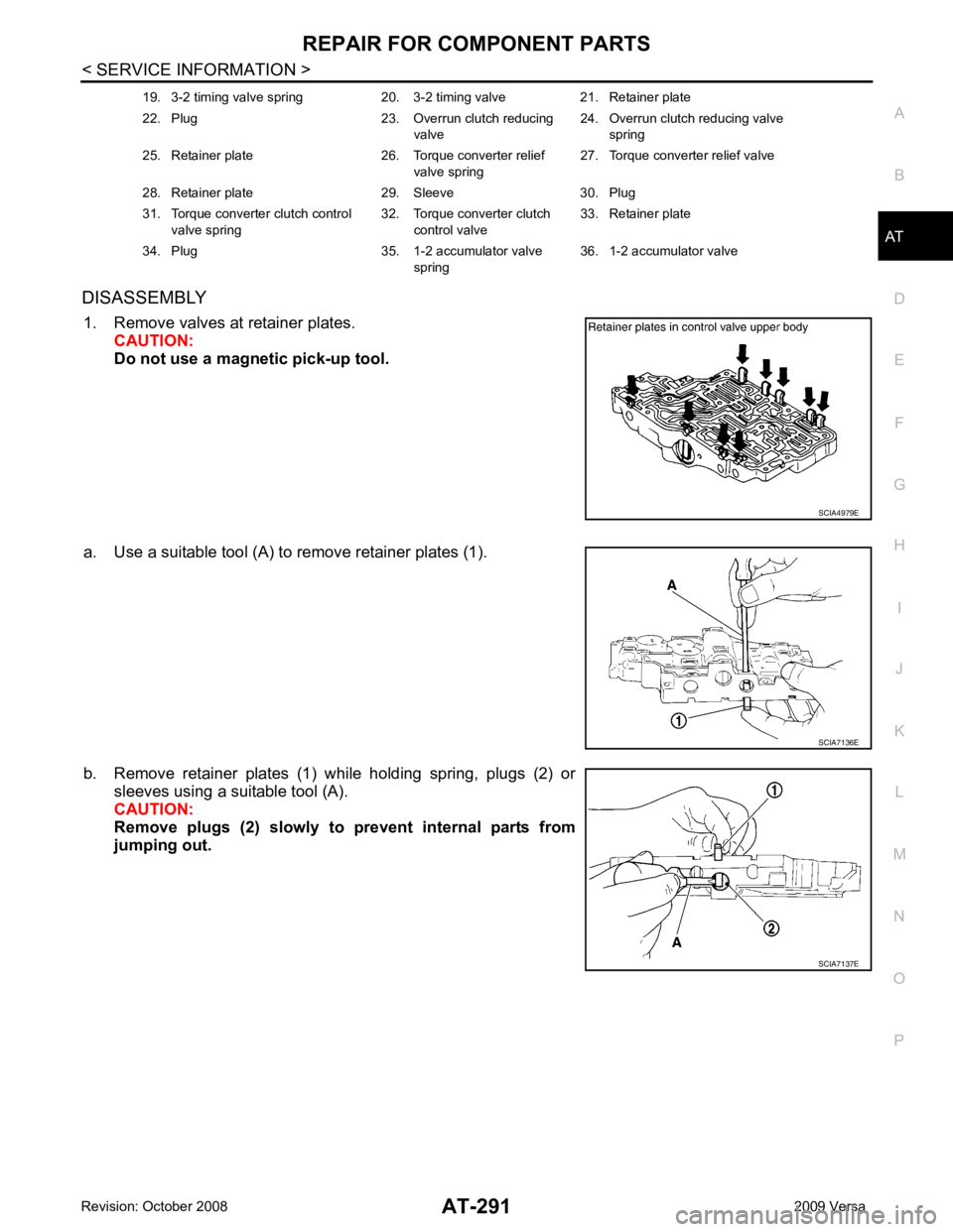
DISASSEMBLY
1. Remove valves at retainer plates. CAUTION:
Do not use a magnetic pick-up tool.
a. Use a suitable tool (A) to remove retainer plates (1).
b. Remove retainer plates (1) while holding spring, plugs (2) or sleeves using a suitable tool (A).
CAUTION:
Remove plugs (2) slowly to prevent internal parts from
jumping out. 19. 3-2 timing valve spring 20. 3-2 timing valve 21. Retainer plate
22. Plug 23. Overrun clutch reducing valve24. Overrun clutch reducing valve
spring
25. Retainer plate 26. Torque converter relief valve spring27. Torque converter relief valve
28. Retainer plate 29. Sleeve 30. Plug
31. Torque converter clutch control valve spring 32. Torque converter clutch
control valve 33. Retainer plate
34. Plug 35. 1-2 accumulator valve spring36. 1-2 accumulator valve
Page 297 of 4331
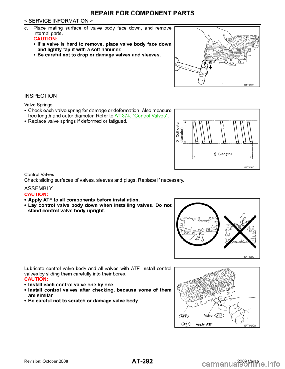
Control Valves " .
• Replace valve springs if deformed or fatigued.
Control Valves
Check sliding surfaces of valves, sl eeves and plugs. Replace if necessary.
ASSEMBLY
CAUTION:
• Apply ATF to all componen ts before installation.
• Lay control valve body down wh en installing valves. Do not
stand control valve body upright.
Lubricate control valve body and all valves with ATF. Install control
valves by sliding them carefully into their bores.
CAUTION:
• Install each control valve one by one.
• Install control valves after checking, because some of them
are similar.
• Be careful not to scratch or damage valve body. SAT138D
SAT140DA
Page 298 of 4331
AT
N
O P
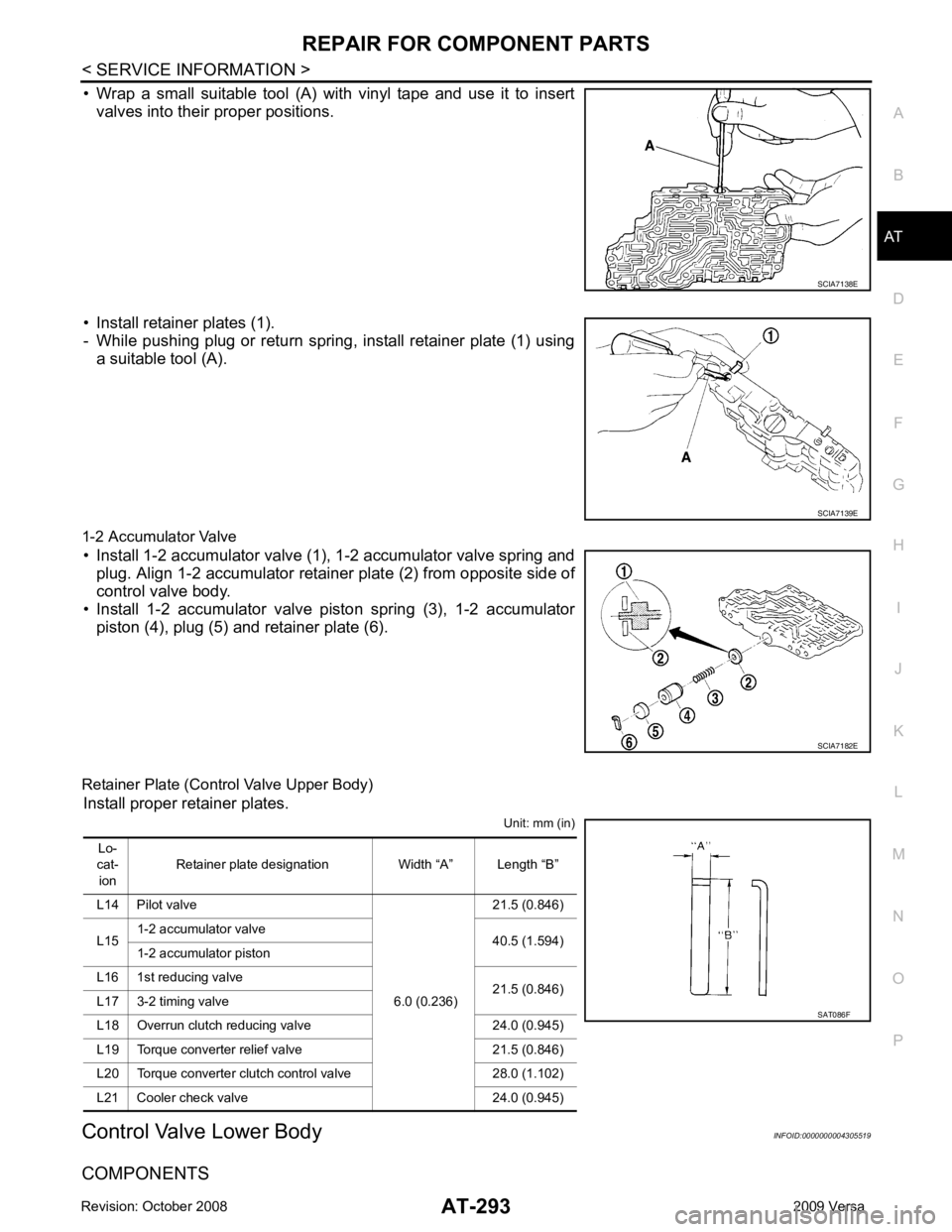
• Wrap a small suitable tool (A) with vinyl tape and use it to insert
valves into their proper positions.
• Install retainer plates (1).
- While pushing plug or return spring, install retainer plate (1) using a suitable tool (A).
1-2 Accumulator Valve • Install 1-2 accumulator valve (1), 1-2 accumulator valve spring and plug. Align 1-2 accumulator retainer plate (2) from opposite side of
control valve body.
• Install 1-2 accumulator valve piston spring (3), 1-2 accumulator
piston (4), plug (5) and retainer plate (6).
Retainer Plate (Control Valve Upper Body) Install proper retainer plates. Unit: mm (in)
Control Valve Lower Body INFOID:0000000004305519
COMPONENTS
Page 300 of 4331
REPAIR FOR COMPONENT PARTS
AT-295
< SERVICE INFORMATION >
D
E
F
G H
I
J
K L
M A
B AT
N
O P
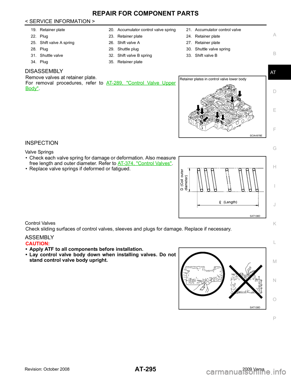
DISASSEMBLY
Remove valves at retainer plate.
For removal procedures, refer to AT-289, " Control Valve Upper
Body " .
INSPECTION
Valve Springs • Check each valve spring for damage or deformation. Also measure free length and outer diameter. Refer to AT-374, " Control Valves " .
• Replace valve springs if deformed or fatigued.
Control Valves Check sliding surfaces of control valves, sl eeves and plugs for damage. Replace if necessary.
ASSEMBLY CAUTION:
• Apply ATF to all componen ts before installation.
• Lay control valve body down wh en installing valves. Do not
stand control valve body upright. 19. Retainer plate 20. Accumulator control valve spring 21. Accumulator control valve
22. Plug 23. Retainer plate 24. Retainer plate
25. Shift valve A spring 26. Shift valve A 27. Retainer plate
28. Plug 29. Shuttle plug 30. Shuttle valve spring
31. Shuttle valve 32. Shift valve B spring 33. Shift valve B
34. Plug 35. Retainer plate SCIA4978E
SAT138D
SAT139D
Page 301 of 4331
AT-296< SERVICE INFORMATION >
REPAIR FOR COMPONENT PARTS
Install control valves.
For installation procedures, refer to AT-289, " Control Valve Upper
Body " .
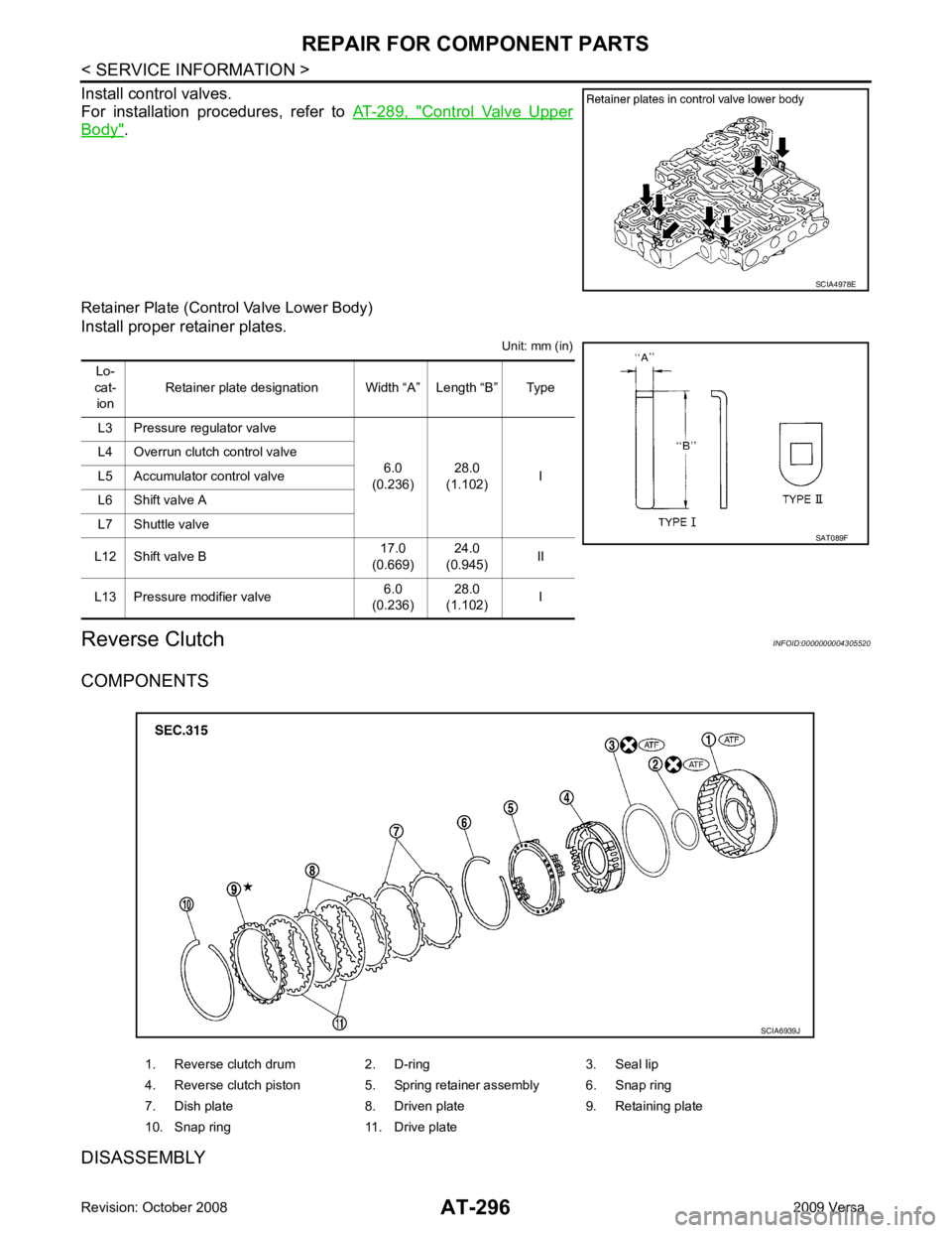
Retainer Plate (Control Valve Lower Body)
Install proper retainer plates. Unit: mm (in)
Reverse Clutch INFOID:0000000004305520
COMPONENTS
DISASSEMBLY SCIA4978E
Lo-
cat- ion Retainer plate designation Width “A” Length “B” Type
L3 Pressure regulator valve 6.0
(0.236) 28.0
(1.102) I
L4 Overrun clutch control valve
L5 Accumulator control valve
L6 Shift valve A
L7 Shuttle valve
L12 Shift valve B 17.0
(0.669) 24.0
(0.945) II
L13 Pressure modifier valve 6.0
(0.236) 28.0
(1.102) I SAT089F
1. Reverse clutch drum 2. D-ring 3. Seal lip
4. Reverse clutch piston 5. Spring retainer assembly 6. Snap ring
7. Dish plate 8. Driven plate 9. Retaining plate
10. Snap ring 11. Drive plate SCIA6939J
Page 373 of 4331
AT-368< SERVICE INFORMATION >
ASSEMBLY
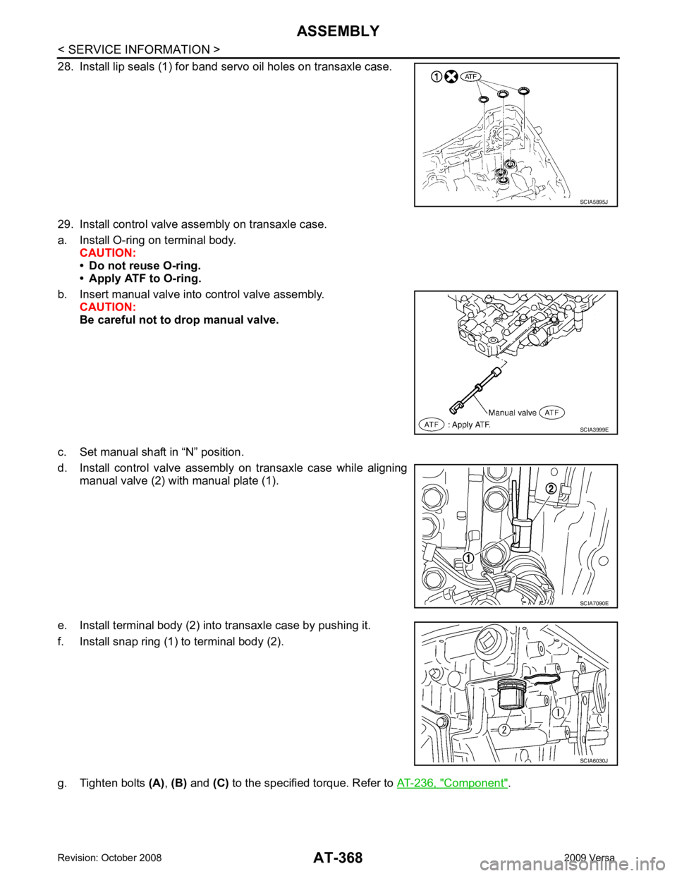
28. Install lip seals (1) for band servo oil holes on transaxle case.
29. Install control valve assembly on transaxle case.
a. Install O-ring on terminal body. CAUTION:
• Do not reuse O-ring.
• Apply ATF to O-ring.
b. Insert manual valve into control valve assembly. CAUTION:
Be careful not to drop manual valve.
c. Set manual shaft in “N” position.
d. Install control valve assembly on transaxle case while aligning manual valve (2) with manual plate (1).
e. Install terminal body (2) into transaxle case by pushing it.
f. Install snap ring (1) to terminal body (2).
g. Tighten bolts (A), (B) and (C) to the specified torque. Refer to AT-236, " Component " . SCIA5895J
SCIA3999E
SCIA7090E
SCIA6030J
Page 380 of 4331
AT
N
O P
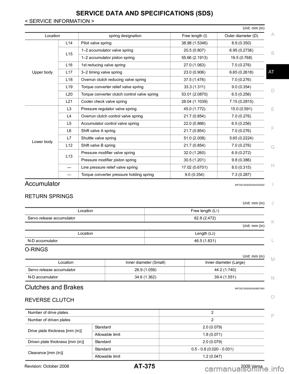
Unit: mm (in)
Accumulator INFOID:0000000004305540
RETURN SPRINGS Unit: mm (in)
Unit: mm (in)
O-RINGS Unit: mm (in)
Clutches and Brakes INFOID:0000000004807940
REVERSE CLUTCH Location spring designation Free length (l) Outer diameter (D)
Upper body L14 Pilot valve spring 38.98 (1.5346) 8.9 (0.350)
L15 1–2 accumulator valve spring 20.5 (0.807) 6.95 (0.2736)
1–2 accumulator piston spring 55.66 (2.1913) 19.5 (0.768)
L16 1st reducing valve spring 27.0 (1.063) 7.0 (0.276)
L17 3–2 timing valve spring 23.0 (0.906) 6.65 (0.2618)
L18 Overrun clutch reducing valve spring 37.5 (1.476) 7.0 (0.276)
L19 Torque converter relief valve spring 33.3 (1.311) 9.0 (0.354)
L20 Torque converter clutch control valve spring 53.01 (2.0870) 6.5 (0.256)
L21 Cooler check valve spring 28.04 (1.1039) 7.15 (0.2815)
Lower body L3 Pressure regulator valve sp
ring 45.0 (1.772) 15.0 (0.591)
L4 Overrun clutch control valve spring 21.7 (0.854) 7.0 (0.276)
L5 Accumulator control valve spring 22.0 (0.866) 6.5 (0.256)
L6 Shift valve A spring 21.7 (0.854) 7.0 (0.276)
L7 Shuttle valve spring 51.0 (2.008) 5.65 (0.2224)
L12 Shift valve B spring 21.7 (0.854) 7.0 (0.276)
L13 Pressure modifier valve spring 32.0 (1.260) 6.9 (0.272)
Pressure modifier piston spring 30.5 (1.201) 9.8 (0.386)
— Line pressure relief valve spring 17.02 (0.6701) 8.0 (0.315)
— Torque converter pressure holding spring 9.0 (0.354) 7.3 (0.287) Location Free length (L
1)
Servo release accumulator 62.8 (2.472) Location Length (L
2)
N-D accumulator 46.5 (1.831)Location Inner diameter (Small) Inner diameter (Large)
Servo release accumulator 26.9 (1.059) 44.2 (1.740)
N-D accumulator 34.6 (1.362) 39.4 (1.551) Number of drive plates
2
Number of driven plates 2
Drive plate thickness [mm (in)] Standard 2.0 (0.079)
Allowable limit 1.8 (0.071)
Driven plate thickness [mm (in)] Standard 2.0 (0.079)
Clearance [mm (in)] Standard 0.5 - 0.8 (0.020 - 0.031)
Allowable limit 1.2 (0.047)
Page 385 of 4331
AV
N
O P
CONTENTS
AUDIO, VISUAL, NAVIGATION & TELEPHONE SYS-
TEM
SERVICE INFORMATION .. ..........................2
PRECAUTIONS .............................................. .....2
Precaution for Supplemental Restraint System
(SRS) "AIR BAG" and "SEAT BELT PRE-TEN-
SIONER" ............................................................. ......
2
PREPARATION .............................................. .....3
Commercial Service Tool .................................... ......3
AUDIO ............................................................ .....4
Component Parts Location .................................. ......4
System Description ............................................. ......4
Schematic ........................................................... ......6
Wiring Diagram - AUDIO - ................................... ......8
Audio Unit (Base System) Harness Connector
Terminal Layout .................................................. ....
16
Terminal and Reference Value for Audio Unit
(Base System) ..................................................... ....
16
Audio Unit (Mid Level and Premium System) Har-
ness Connector Terminal Layout ........................ ....
17
Terminal and Reference Value for Audio Unit (Mid
Level and Premium System) ............................... ....
17
Subwoofer Harness Connector Terminal Layout
(Premium Audio System) .................................... ....
20
Terminal and Reference Value for Subwoofer
(Premium Audio System) .................................... ....
20
Satellite Radio Tuner Ha rness Connector Termi-
nal Layout ............................................................ ....
20
Terminal and Reference Value for Satellite Radio
Tuner ................................................................... ....
21
Trouble Diagnosis ............................................... ....21
Noise Inspection .................................................. ....22
Power Supply Circuit Inspection ......................... ....23
Satellite Radio Tuner (Fac tory Installed) Power
and Ground Supply Circuit Inspection ................. ....
24
Satellite Radio Tuner (Fac tory Installed) Commu-
nication Circuit Inspection ................................... ....
25
Satellite Radio Tuner (Fac tory Installed) Left
Channel Audio Signal Circuit Inspection ............. ....
27 Satellite Radio Tuner (Fac
tory Installed) Right
Channel Audio Signal Circuit Inspection ............. ....
27
Steering Switch Check (With Bluetooth) .............. ....28
Sound Is Not Heard from Front Door Speaker
(Base System) ..................................................... ....
30
Sound Is Not Heard from Rear Door Speaker
(Base System) ..................................................... ....
31
Sound Is Not Heard from Front Door Speaker or
Tweeter (Mid Level and Premium System) .............
32
Sound Is Not Heard from Rear Door Speaker (Mid
Level and Premium System) ............................... ....
33
Sound Is Not Heard from Subwoofer (Premium
System) ............................................................... ....
35
Removal and Installation ..................................... ....37
AUDIO ANTENNA ............................................. 42
Location of Antenna ............................................. ....42
Removal and Installation of Roof Antenna ..............42
TELEPHONE ..................................................... 44
Component Parts and Harness Connector Loca-
tion ....................................................................... ....
44
System Description .............................................. ....44
Wiring Diagram - H/PHON - ................................ ....46
Bluetooth Control Unit Harness Connector Termi-
nal Layout ............................................................ ....
48
Terminal and Reference Value for Bluetooth Con-
trol Unit ................................................................ ....
48
Bluetooth Control Unit Se lf-Diagnosis Function ......49
Workflow .............................................................. ....50
Power Supply and Ground Circuit Inspection for
Bluetooth Control Unit .. ...........................................
50
Basic Inspection of Hands-Free Phone ............... ....51
Steering Wheel Audio Co ntrol Switch Does Not
Operate ................................................................ ....
52
Voice Activated Control Fu nction Does Not Oper-
ate ........................................................................ ....
53
Removal and Installation ..................................... ....55