Page 223 of 4331
Selector Lever Knob Removal and Installation " .
3. Remove the center console assembly. Refer to IP-11 .
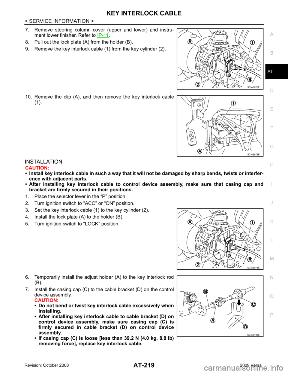
4. Slide the slider (A) toward the casing cap (B) while pressing tabs (C) on the slider to separate the slider (A) from the adjust holder
(D).
5. Remove the casing cap (B) from the cable bracket on the control
device assembly.
6. Remove the key interlock cable from the key interlock rod (E). 1. Key interlock cable 2. Key cylinder 3. Control device assembly
A. Lock plate B. Holder C. Clip
D. Slider E. Key interlock rod F. Adjust holder
G. Casing cap SCIA6975E
Page 224 of 4331

AT
N
O P
7. Remove steering column cover (upper and lower) and instru-
ment lower finisher. Refer to IP-11 .
8. Pull out the lock plate (A) from the holder (B).
9. Remove the key interlock cable (1) from the key cylinder (2).
10. Remove the clip (A), and then remove the key interlock cable (1).
INSTALLATION CAUTION:
• Install key interlock cable in such a way that it will not be damaged by sharp bends, twists or interfer-
ence with adjacent parts.
• After installing key interlock cable to contro l device assembly, make sure that casing cap and
bracket are firmly secured in their positions.
1. Place the selector lever in the “P” position.
2. Turn ignition switch to “ACC” or “ON” position.
3. Set the key interlock cable (1) to the key cylinder (2).
4. Install the lock plate (A) to the holder (B).
5. Turn ignition switch to “LOCK” position.
6. Temporarily install the adjust holder (A) to the key interlock rod (B).
7. Install the casing cap (C) to the cable bracket (D) on the control device assembly.
CAUTION:
• Do not bend or twist key interlock cable excessively when
installing.
• After installing key interlo ck cable to cable bracket (D) on
control device assembly, make sure casing cap (C) is
firmly secured in cable bracket (D) on control device
assembly.
• If casing cap (C) is loose [less than 39.2 N (4.0 kg, 8.8 lb)
removing force], replace key interlock cable.
Page 226 of 4331

AT
N
O P
ON-VEHICLE SERVICE
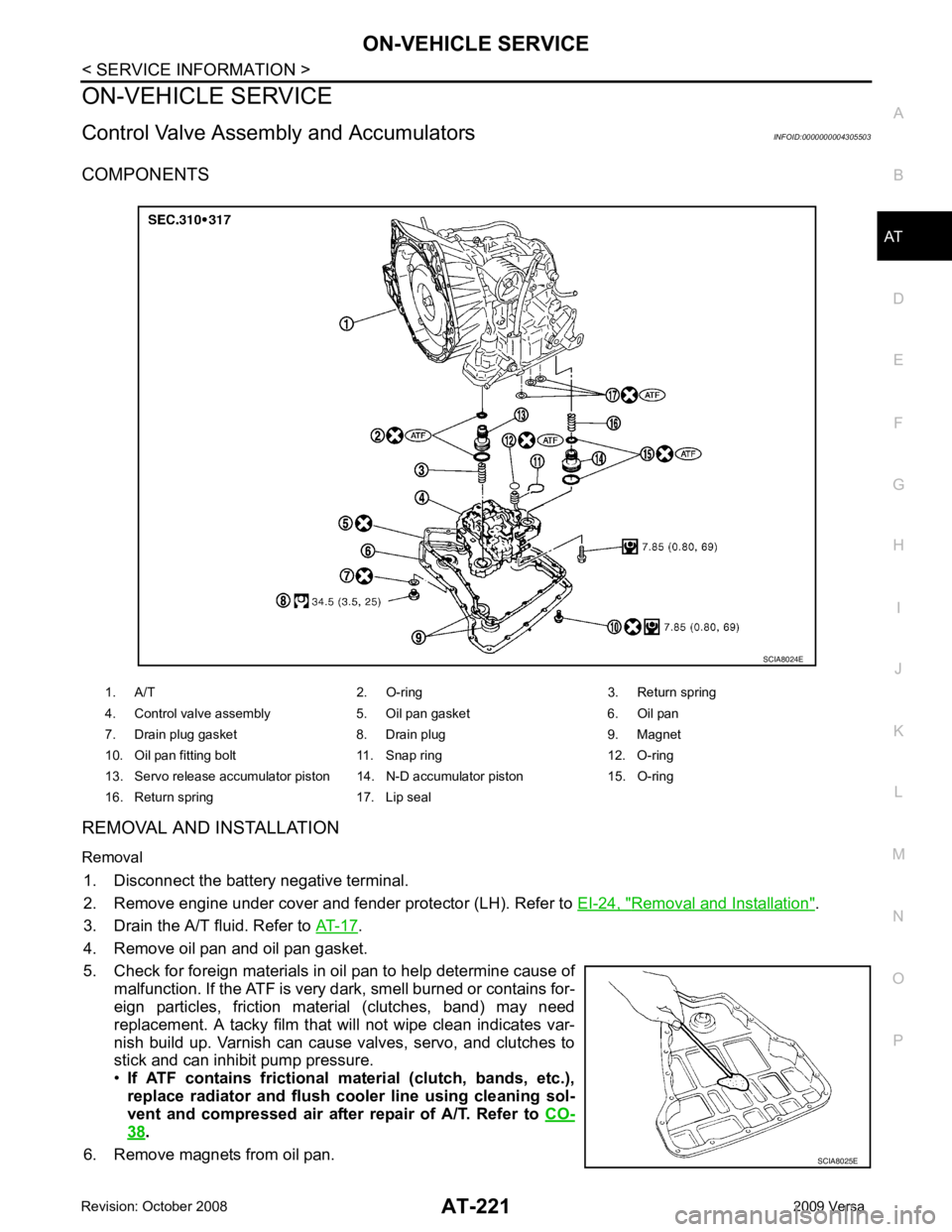
Control Valve Assembly and Accumulators INFOID:0000000004305503
COMPONENTS
REMOVAL AND INSTALLATION
Removal 1. Disconnect the battery negative terminal.
2. Remove engine under cover and fender protector (LH). Refer to EI-24, " Removal and Installation " .
3. Drain the A/T fluid. Refer to AT-17 .
4. Remove oil pan and oil pan gasket.
5. Check for foreign materials in oil pan to help determine cause of malfunction. If the ATF is very dark, smell burned or contains for-
eign particles, friction material (clutches, band) may need
replacement. A tacky film that will not wipe clean indicates var-
nish build up. Varnish can cause valves, servo, and clutches to
stick and can inhibit pump pressure.
• If ATF contains frictional material (clutch, bands, etc.),
replace radiator and flush cooler line using cleaning sol-
vent and compressed air after repair of A/T. Refer to CO-38 .
6. Remove magnets from oil pan. 1. A/T 2. O-ring 3. Return spring
4. Control valve assembly 5. Oil pan gasket 6. Oil pan
7. Drain plug gasket 8. Drain plug 9. Magnet
10. Oil pan fitting bolt 11. Snap ring 12. O-ring
13. Servo release accumulator piston 14. N-D accumulator piston 15. O-ring
16. Return spring 17. Lip seal SCIA8025E
Page 227 of 4331
Control Valve Assembly " ,
AT-289, " Control
Valve Upper Body " and
AT-293, " Control Valve Lower Body " .
15. Remove servo release accumulator piston and N-D accumulator piston by applying compressed air if necessary.
CAUTION:
Hold each piston wi th lint-free cloth. SCIA4854E
Page 229 of 4331
Accumulator " for free length (L
1) and
length (L 2
).
(1): Return spring (Servo release accumulator)
(2): Return spring (N-D accumulator)
CAUTION:
Do not remove spring retainer (3).
Installation
Installation is in the reverse order of removal.
CAUTION:
• Completely remove all moisture, oil and old gasket from the oil pan gasket mounting surface of tran-
saxle case and oil pan.
• Do not reuse O-rings, lip seals, oil pan gasket and oil pan bolts.
• Apply ATF to manual valve, O-rings, li p seals and sliding surfaces of the transaxle case.
NOTE:
• Set manual shaft in “N” position, then align manual plate (1) with
groove in manual valve (2).
• After installing control valve assembly to transaxle case, make sure that selector lever can be moved to all positions.
• After completing installation, check for A/T fluid leakage and A/T fluid level. Refer to AT-17, " Checking A/T Fluid " .
Park/Neutral Position (PNP) Switch INFOID:0000000004305504
COMPONENTS
Page 230 of 4331
AT
N
O P
REMOVAL AND INSTALLATION
Removal 1. Disconnect the battery negative terminal.
2. Remove air duct (inlet). Refer to EM-139 .
3. Remove control cable (1) from manual shaft. Refer to AT-212," Control Device Removal and Installation " .
4. Disconnect PNP switch harness connector (2).
5. Remove PNP switch bolts.
6. Set manual shaft in “P” position.
7. Remove PNP switch from A/T.
Installation Installation is in the reverse order of removal.
NOTE:
• Align PNP switch position when installing.
• After installation is completed, adjust and check the PNP switch and A/T position. Refer to "PARK/NEUTRAL
POSITION (PNP) SWITCH ADJUSTMENT", AT-216, " Adjustment of A/T Position " and
AT-216, " Checking of
A/T Position " .
• After installation is completed, check continuity of PNP switch. Refer to AT-176, " Component Inspection " .
PARK/NEUTRAL POSITION (PNP) SWITCH ADJUSTMENT 1. Remove air duct (inlet). Refer to EM-139 .
1. A/T 2. PNP switch
Page 231 of 4331
![NISSAN TIIDA 2009 Service Repair Manual " Control Device Removal and Installation " .
4. Loosen PNP switch bolts. :Bolt
5. Insert the pin (3) [4 mm (0.16 in) dia.] straight into manual shaft (1) adjustment hole.
6. Rotate PNP switch (2) NISSAN TIIDA 2009 Service Repair Manual " Control Device Removal and Installation " .
4. Loosen PNP switch bolts. :Bolt
5. Insert the pin (3) [4 mm (0.16 in) dia.] straight into manual shaft (1) adjustment hole.
6. Rotate PNP switch (2)](/manual-img/5/57398/w960_57398-230.png)
" Control Device Removal and Installation " .
4. Loosen PNP switch bolts. :Bolt
5. Insert the pin (3) [4 mm (0.16 in) dia.] straight into manual shaft (1) adjustment hole.
6. Rotate PNP switch (2) until the pin (3) can also be inserted straight into hole in PNP switch (2).
7. Tighten PNP switch bolts to the specified torque. Refer to "COMPONENTS".
8. Remove the pin (3) from adjustment hole after adjusting PNP switch (2).
9. Install the control cable. Refer to AT-212, " Control Device Removal and Installation " .
10. Adjust and check A/T position. Refer to AT-216, " Adjustment of A/T Position " and
AT-216, " Checking of A/
T Position " .
11. Check continuity of PNP switch (2). Refer to AT-176, " Component Inspection " .
12. Install the air duct (inlet). Refer to EM-139 .
Revolution Sensor INFOID:0000000004305505
COMPONENTS
REMOVAL AND INSTALLATION
Removal
1. Disconnect the battery negative terminal.
2. Remove air duct (inlet), air duct and air cleaner case. Refer to EM-139, " Component " .
Page 263 of 4331
.
14. Remove magnets from oil pan.
15. Remove control valve assembly according to the following procedures.
a. Remove snap ring (1) from terminal body (2). CAUTION:
Do not expand snap ring (1) excessively.
b. Push terminal body (2) into transaxle case.
c. Remove control valve assembly fitting bolts (A), (B) and ( C).
Bolt length, number and location:
d. Remove control valve assembly from transaxle case. CAUTION:
Be careful not to drop manual valve. SCIA8025E
SCIA6030J