2009 NISSAN TIIDA Heater blower
[x] Cancel search: Heater blowerPage 3886 of 4331

MTC
N
O P
CONTENTS
MANUAL AIR CONDITIONER
SERVICE INFORMATION .. ..........................3
PRECAUTIONS .............................................. .....3
Precaution for Supplemental Restraint System
(SRS) "AIR BAG" and "SEAT BELT PRE-TEN-
SIONER" ............................................................. ......
3
Precaution Necessary fo r Steering Wheel Rota-
tion After Battery Disconnect ............................... ......
3
Precaution for Procedure without Cowl Top Cover ......4
Precaution for Working with HFC-134a (R-134a) ......4
General Refrigerant Precaution .......................... ......4
Oil Precaution ...................................................... ......5
Precaution for Refrigeran t Connection ......................5
Precaution for Service of Compressor ................ ......7
Precaution for Service Equipment ....................... ......8
Precaution for Leak Detection Dye ..................... ......9
PREPARATION .............................................. ....11
HFC-134a (R-134a) Service Tool and Equipment ....11
Commercial Service Tool .................................... ....13
REFRIGERATION SYSTEM .......................... ....15
Refrigerant Cycle ................................................ ....15
Refrigerant System Protec tion ................................15
Component Part Location ................................... ....16
OIL .................................................................. ....17
Maintenance of Oil Quantity in Compressor ....... ....17
AIR CONDITIONER CONTROL ..................... ....19
Control Operation ................................................ ....19
Discharge Air Flow .............................................. ....20
System Description ............................................. ....20
TROUBLE DIAGNOSIS ................................. ....22
CONSULT-II Function (BCM) .............................. ....22
How to Perform Trouble Diagnosis for Quick and
Accurate Repair ........... ...........................................
22
Component Parts and Harness Connector Loca-
tion ...................................................................... ....
23
Schematic ........................................................... ....25
Wiring Diagram - Heater - ................................... ....26 Wiring Diagram - A/C,M - ....................................
....27
Operational Check ............................................... ....30
Mode Door ........................................................... ....31
Air Mix Door ......................................................... ....32
Intake Door .......................................................... ....33
Front Blower Motor Circuit .......................................33
Magnet Clutch Circuit (If Equipped) ..................... ....37
Insufficient Cooling .............................................. ....45
Insufficient Heating .............................................. ....52
Noise ................................................................... ....53
CONTROLLER .................................................. 55
Removal and Installation ..................................... ....55
Disassembly and Assembly ................................. ....56
THERMO CONTROL AMPLIFIER .................... 57
Removal and Installation ..................................... ....57
A/C UNIT ASSEMBLY ...................................... 58
Removal and Installation ..................................... ....58
Disassembly and Assembly ................................. ....60
BLOWER MOTOR ............................................ 62
Removal and Installation ..................................... ....62
INTAKE DOOR .................................................. 63
Intake Door Cable Adjustment ............................. ....63
AIR MIX DOOR ................................................. 64
Air Mix Door Cable Adjustment ........................... ....64
MODE DOOR .................................................... 65
Mode Door Cable Adjustment ............................. ....65
BLOWER FAN RESISTOR ............................... 66
Removal and Installation ..................................... ....66
HEATER CORE ................................................. 67
Removal and Installation ..................................... ....67
AIR CONDITIONER FILTER ............................. 68
Removal and Installation ..................................... ....68
Page 3974 of 4331

MTC
N
O P
Check all around the service valves. Ensure service valve caps are secured on the service valves (to
prevent leaks).
NOTE:
After removing A/C manifold gauge set from service va lves, wipe any residue from valves to prevent any
false readings by leak detector.
• Cooling unit (Evaporator)
With engine OFF, turn blower fan on “High” for at least 15 seconds to dissipate any refrigerant trace in
the cooling unit. Wait a minimum of 10 minutes ac cumulation time (refer to the manufacturer’s recom-
mended procedure for actual wait time) before inserting the leak detector probe into the drain hose.
Keep the probe inserted for at least 10 seconds. Use c aution not to contaminate the probe tip with water
or dirt that may be in the drain hose.
5. If a leak detector detects a leak, verify at least once by blowing compressed air into area of suspected
leak, then repeat check as outlined above.
6. Do not stop when one leak is found. Continue to check for additional leaks at all system components.
If no leaks are found, perform steps 7-10.
7. Start engine.
8. Set the heater A/C control as follows;
a. A/C switch: ON
b. Mode control dial position: VENT (Ventilation)
c. Intake door lever position: Recirculation
d. Max. cold temperature
e. Fan speed: High
9. Run engine at 1,500 rpm for at least 2 minutes.
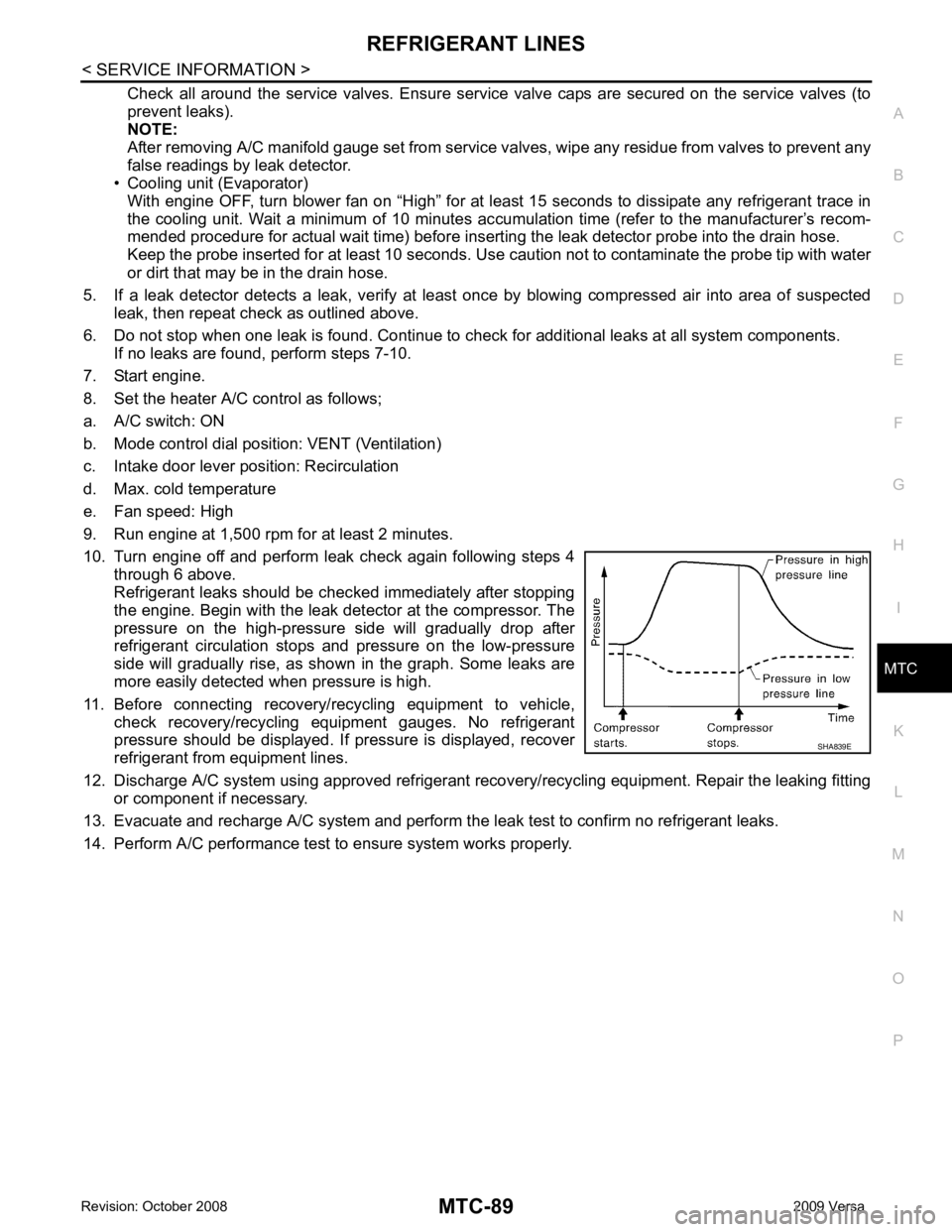
10. Turn engine off and perform leak check again following steps 4 through 6 above.
Refrigerant leaks should be chec ked immediately after stopping
the engine. Begin with the leak detector at the compressor. The
pressure on the high-pressure side will gradually drop after
refrigerant circulation stops and pressure on the low-pressure
side will gradually rise, as shown in the graph. Some leaks are
more easily detected when pressure is high.
11. Before connecting recovery/recycling equipment to vehicle, check recovery/recycling equipment gauges. No refrigerant
pressure should be displayed. If pressure is displayed, recover
refrigerant from equipment lines.
12. Discharge A/C system using approved refrigerant reco very/recycling equipment. Repair the leaking fitting
or component if necessary.
13. Evacuate and recharge A/C system and perform the l eak test to confirm no refrigerant leaks.
14. Perform A/C performance test to ensure system works properly.