2009 NISSAN TIIDA exterior
[x] Cancel search: exteriorPage 24 of 4331
A/T FLUID
AT-19
< SERVICE INFORMATION >
D
E
F
G H
I
J
K L
M A
B AT
N
O P
13. Flush each steel line from the cooler side back to
ward the A/T by spraying Transmission Cooler Cleaner
in a continuous stream for 5 seconds.
14. Blow compressed air regulated to 5 - 9 kg/cm 2
(71 - 128 psi) through each steel line from the cooler side
back toward the A/T for 10 seconds to force out any remaining A/T fluid.
15. Ensure all debris is removed from the steel cooler lines.
16. Ensure all debris is removed from the banjo bolts and fittings.
17. Perform "A/T FLUID COOL ER DIAGNOSIS PROCEDURE".
A/T FLUID COOLER DIAGNOSIS PROCEDURE NOTE:
Insufficient cleaning of the cooler inlet hose exte rior may lead to inaccurate debris identification.
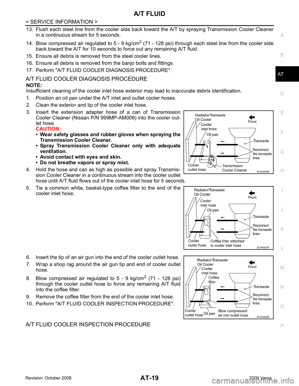
1. Position an oil pan under the A/T inlet and outlet cooler hoses.
2. Clean the exterior and tip of the cooler inlet hose.
3. Insert the extension adapter hose of a can of Transmission Cooler Cleaner (Nissan P/N 999MP-AM006) into the cooler out-
let hose.
CAUTION:
• Wear safety glasses and rubber gloves when spraying the
Transmission Cooler Cleaner.
• Spray Transmission Cooler Cleaner only with adequate
ventilation.
• Avoid contact with eyes and skin.
• Do not breathe vapors or spray mist.
4. Hold the hose and can as high as possible and spray Transmis- sion Cooler Cleaner in a continuous stream into the cooler outlet
hose until A/T fluid flows out of t he cooler inlet hose for 5 seconds.
5. Tie a common white, basket-type coffee filter to the end of the cooler inlet hose.
6. Insert the tip of an air gun into the end of the cooler outlet hose.
7. Wrap a shop rag around the air gun tip and end of cooler outlet hose.
8. Blow compressed air regulated to 5 - 9 kg/cm 2
(71 - 128 psi)
through the cooler outlet hose to force any remaining A/T fluid
into the coffee filter.
9. Remove the coffee filter from the end of the cooler inlet hose.
10. Perform "A/T FLUID COOL ER INSPECTION PROCEDURE".
A/T FLUID COOLER INSPECTION PROCEDURE SCIA5629E
SCIA5631E
SCIA5632E
Page 464 of 4331
BL
N
O P
Check Trunk Lid Opener S
witch Circuit (With Intel-
ligent Key) ........................................................... ..
212
Check Trunk Release Solenoid Circuit ............... ..214
FUEL FILLER LID OPENER .......................... ..217
Removal and Installation of Fuel Filler Lid Opener ..217
VEHICLE SECURITY (THEFT WARNING)
SYSTEM ......................................................... ..
218
Component Parts and Harness Connector Loca-
tion ...................................................................... ..
218
System Description ............................................. ..219
CAN Communication System Description ........... ..221
Schematic ........................................................... ..222
Wiring Diagram - VEHSEC - ............................... ..223
Terminal and Reference Value for BCM ............. ..227
Terminal and Re ference Value for Intelligent Key
Unit ...................................................................... ..
231
CONSULT-III Function (BCM) ............................. ..233
Trouble Diagnosis ............................................... ..235
Preliminary Check ............................................... ..235
Symptom Chart ................................................... ..237
Diagnosis Procedure 1 ........................................ ..238
Diagnosis Procedure 2 ........................................ ..241
Diagnosis Procedure 3 ........................................ ..242
Diagnosis Procedure 4 ........................................ ..242
Diagnosis Procedure 5 ........................................ ..242
Diagnosis Procedure 6 ........................................ ..242
Diagnosis Procedure 7 ........................................ ..242
Diagnosis Procedure 8 ........................................ ..244
Diagnosis Procedure 9 ........................................ ..245 NATS (Nissan Anti-Theft System) ................
248
Component Parts and Harness Connector Loca-
tion ....................................................................... ..
248
System Description .............................................. ..248
System Composition ............................................ ..249
ECM Re-communicating Function ....................... ..249
Wiring Diagram - NATS - ..................................... ..251
Terminal and Reference Value for BCM ................252
CONSULT-III Function ........................................ ..256
Trouble Diagnosis Procedure .............................. ..257
Trouble Diagnosis ................................................ ..259
Diagnosis Procedure 1 ........................................ ..260
Diagnosis Procedure 2 ........................................ ..262
Diagnosis Procedure 3 ........................................ ..263
Diagnosis Procedure 4 ........................................ ..264
Diagnosis Procedure 5 ........................................ ..265
Diagnosis Procedure 6 ........................................ ..266
How to Replace NATS Antenna Amp .................. ..266
BODY REPAIR ................................................ 267
Body Exterior Paint Color .................................... ..267
Body Component Parts ....................................... ..269
Corrosion Protection ............................................ ..274
Body Sealing ....................................................... ..278
Body Construction ............................................... ..284
Body Alignment ................................................... ..286
Handling Precaution for Plastics .......................... ..303
Precaution in Repairing High Strength Steel ....... ..307
Foam Repair ........................................................ ..310
Replacement Operation ....................................... ..313
Page 728 of 4331
BL
N
O P
BODY REPAIR
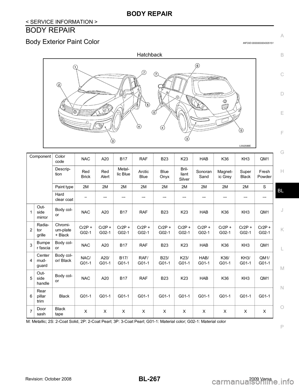
Body Exterior Paint Color INFOID:0000000004305151
Hatchback
M: Metallic; 2S: 2-Coat Solid, 2P: 2-Coat Pearl; 3P: 3-Coat Pearl; G01-1: Material color; G02-1: Material color
Page 766 of 4331
BL
N
O P
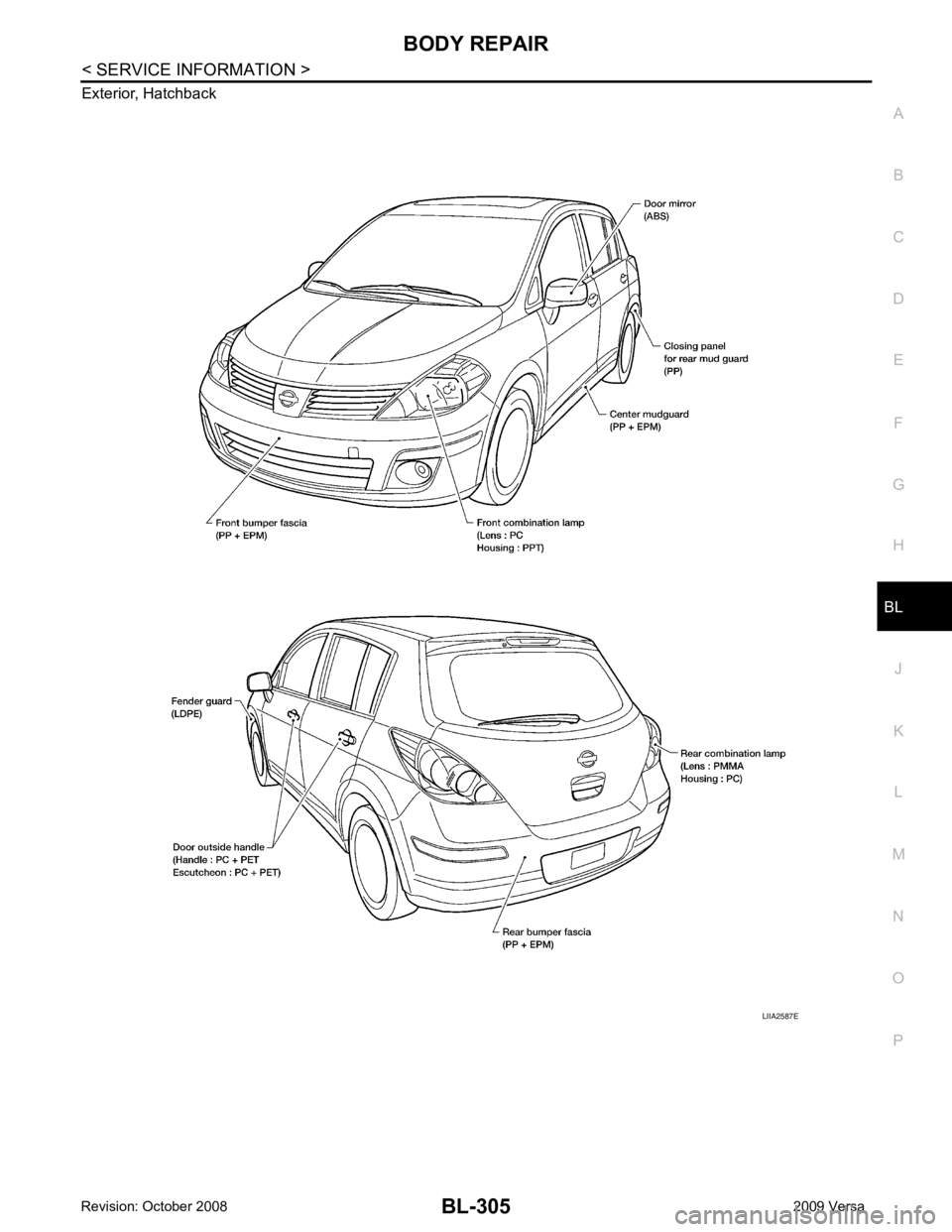
Exterior, Hatchback
Page 963 of 4331
CVT
N
O P
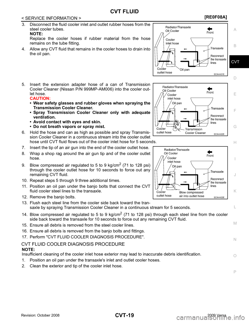
3. Disconnect the fluid cooler inle
t and outlet rubber hoses from the
steel cooler tubes.
NOTE:
Replace the cooler hoses if rubber material from the hose
remains on the tube fitting.
4. Allow any CVT fluid that remains in the cooler hoses to drain into the oil pan.
5. Insert the extension adapter hose of a can of Transmission Cooler Cleaner (Nissan P/N 999MP-AM006) into the cooler out-
let hose.
CAUTION:
• Wear safety glasses and rubber gloves when spraying the Transmission Cooler Cleaner.
• Spray Transmission Cooler Cleaner only with adequate
ventilation.
• Avoid contact with eyes and skin.
• Do not breath vapors or spray mist.
6. Hold the hose and can as high as possible and spray Transmis- sion Cooler Cleaner in a continuous stream into the cooler outlet
hose until CVT fluid flows out of t he cooler inlet hose for 5 seconds.
7. Insert the tip of an air gun into the end of the cooler outlet hose.
8. Wrap a shop rag around the air gun tip and of the cooler outlet hose.
9. Blow compressed air regulated to 5 to 9 kg/cm 2
(71 to 128 psi)
through the cooler outlet hose for 10 seconds to force out any
remaining CVT fluid.
10. Repeat steps 5 through 9 three additional times.
11. Position an oil pan under the banjo bolts that connect the CVT fluid cooler steel lines to the transaxle.
12. Remove the banjo bolts.
13. Flush each steel line from the cooler side back toward the tran- saxle by spraying Transmission Cooler Cleaner in a continuous stream for 5 seconds.
14. Blow compressed air regulated to 5 to 9 kg/cm 2
(71 to 128 psi) through each steel line from the cooler
side back toward the transaxle for 10 seconds to force out any remaining CVT fluid.
15. Ensure all debris is removed from the steel cooler lines.
16. Ensure all debris is removed from the banjo bolts and fittings.
17. Perform "CVT FLUID COOLER DIAGNOSIS PROCEDURE".
CVT FLUID COOLER DIAGNOSIS PROCEDURE NOTE:
Insufficient cleaning of the cooler inlet hose exte rior may lead to inaccurate debris identification.
1. Position an oil pan under the transax le's inlet and outlet cooler hoses.
2. Clean the exterior and tip of the cooler inlet hose.
Page 1142 of 4331
![NISSAN TIIDA 2009 Service Repair Manual CVT-198< SERVICE INFORMATION >
[RE0F08B]
CVT FLUID
3. Disconnect the fluid cooler inle t and outlet rubber hoses from the
steel cooler tubes.
NOTE:
Replace the cooler hoses if rubber material f NISSAN TIIDA 2009 Service Repair Manual CVT-198< SERVICE INFORMATION >
[RE0F08B]
CVT FLUID
3. Disconnect the fluid cooler inle t and outlet rubber hoses from the
steel cooler tubes.
NOTE:
Replace the cooler hoses if rubber material f](/manual-img/5/57398/w960_57398-1141.png)
CVT-198< SERVICE INFORMATION >
[RE0F08B]
CVT FLUID
3. Disconnect the fluid cooler inle t and outlet rubber hoses from the
steel cooler tubes.
NOTE:
Replace the cooler hoses if rubber material from the hose
remains on the tube fitting.
4. Allow any CVT fluid that remains in the cooler hoses to drain into the oil pan.
5. Insert the extension adapter hose of a can of Transmission
Cooler Cleaner (Nissan P/N 999MP-AM006) into the cooler out-
let hose.
CAUTION:
• Wear safety glasses and rubber gloves when spraying the Transmission Cooler Cleaner.
• Spray Transmission Cooler Cleaner only with adequate
ventilation.
• Avoid contact with eyes and skin.
• Do not breath vapors or spray mist.
6. Hold the hose and can as high as possible and spray Transmis- sion Cooler Cleaner in a continuous stream into the cooler outlet
hose until CVT fluid flows out of the cooler inlet hose for 5 seconds.
7. Insert the tip of an air gun into the end of the cooler outlet hose.
8. Wrap a shop rag around the air gun tip and of the cooler outlet hose.
9. Blow compressed air regulated to 5 to 9 kg/cm 2
(71 to 128 psi)
through the cooler outlet hose for 10 seconds to force out any
remaining CVT fluid.
10. Repeat steps 5 through 9 three additional times.
11. Position an oil pan under the banjo bolts that connect the CVT fluid cooler steel lines to the transaxle.
12. Remove the banjo bolts.
13. Flush each steel line from the cooler side back toward the tran- saxle by spraying Transmission Cooler Cleaner in a continuous stream for 5 seconds.
14. Blow compressed air regulated to 5 to 9 kg/cm 2
(71 to 128 psi) through each steel line from the cooler
side back toward the transaxle for 10 seconds to force out any remaining CVT fluid.
15. Ensure all debris is removed from the steel cooler lines.
16. Ensure all debris is removed from the banjo bolts and fittings.
17. Perform "CVT FLUID COOLER DIAGNOSIS PROCEDURE".
CVT FLUID COOLER DIAGNOSIS PROCEDURE
NOTE:
Insufficient cleaning of the cooler inlet hose exte rior may lead to inaccurate debris identification.
1. Position an oil pan under the transaxle's inlet and outlet cooler hoses.
2. Clean the exterior and tip of the cooler inlet hose. SCIA4421E
SCIA4422E
SCIA4423E
Page 2892 of 4331
EI
N
O P
CONTENTS
EXTERIOR & INTERIOR
PRECAUTION ....... ........................................3
PRECAUTIONS .............................................. .....3
Precaution for Supplemental Restraint System
(SRS) "AIR BAG" and "SEAT BELT PRE-TEN-
SIONER" ............................................................. ......
3
Precaution Necessary fo r Steering Wheel Rota-
tion After Battery Disconnect ............................... ......
3
Precaution ........................................................... ......4
PREPARATION .... ........................................5
PREPARATION .............................................. .....5
Special Service Tool ........................................... ......5
Commercial Service Tool .................................... ......5
SYMPTOM DIAGNOSIS ..... ..........................6
SQUEAK AND RATTLE TROUBLE DIAGNO-
SIS .................................................................. .....6
Work Flow ........................................................... ......6
Generic Squeak and Rattle Troubleshooting ...... ......8
Diagnostic Worksheet ......................................... ....10
CLIP AND FASTENER ................................... ....12
Description .......................................................... ....12
ON-VEHICLE REPAIR .... .............................15
FRONT BUMPER ........................................... ....15
Removal and Installation .........................................15
REAR BUMPER ............................................. ....17
Component .......................................................... ....17
Removal and Installation - Hatchback .....................18
Removal and Installation - Sedan ....................... ....19
FRONT GRILLE ............................................. ....21
Removal and Installation .........................................21
COWL TOP ..................................................... ....22
Removal and Installation .........................................22 FENDER PROTECTOR ....................................
24
Component .......................................................... ....24
Removal and Installation ..................................... ....24
ROOF SIDE MOLDING ..................................... 25
Component .......................................................... ....25
Removal and Installation ..................................... ....25
DOOR OUTSIDE MOLDING ............................. 27
Component .......................................................... ....27
Removal and Installation ..................................... ....28
CENTER MUD GUARD ..................................... 30
Removal and Installation ..................................... ....30
TRUNK LID FINISHER ...................................... 31
Removal and Installation ..................................... ....31
REAR AIR SPOILER ......................................... 32
Removal and Installation ..................................... ....32
DOOR FINISHER .............................................. 34
Removal and Installation ..................................... ....34
BACK DOOR TRIM ........................................... 38
Removal and Installation ..................................... ....38
BODY SIDE TRIM ............................................. 39
Component .......................................................... ....39
Removal and Installation ..................................... ....40
REAR PARCEL SHELF FINISHER .................. 44
Removal and Installation ..................................... ....44
FLOOR TRIM .................................................... 45
Removal and Installation ..................................... ....45
HEADLINING .................................................... 47
Component .......................................................... ....47
Removal and Installation - Hatchback ................. ....49
Removal and Installation - Sedan ........................ ....51
LUGGAGE FLOOR TRIM ................................. 53
Page 3611 of 4331
LT
N
O P
• to BCM terminal 67
• to combination meter terminals 21, 22 and 23
• through grounds M57 and M61, and
• to IPDM E/R terminals 39 and 59
• through grounds E15 and E24.
HEADLAMP OPERATION
Low Beam Operation With the lighting switch in 2ND position, the BCM re ceives an input signal requesting the headlamps to illumi-
nate. The BCM then sends a signal, via the CAN comm unication lines, to the IPDM E/R requesting the low
beam headlamps be turned ON. The CPU located in the IPDM E/R controls ground to the headlamp low relay
coil, which when energized, directs power
• through 15A fuse (No. 41, located in IPDM E/R)
• through IPDM E/R terminal 54
• to headlamp RH terminal 3, and
• through 15A fuse (No. 40, located in IPDM E/R)
• through IPDM E/R terminal 52
• to headlamp LH terminal 3.
Ground is supplied
• to headlamp RH and LH terminals 2
• through grounds E15 and E24.
With power and ground supplied, low beam headlamps illuminate.
High Beam Operation/Flash-to-Pass Operation With the lighting switch in 2ND position and high beam s witch in the HIGH position, the BCM receives an input
signal requesting the headlamp high beams to illuminate. The flash to pass feature can be used any time and
also sends a signal to the BCM. This input signal is then communicated to the IPDM E/R and the combination
meter via the CAN communication. The CPU located in the IPDM E/R controls the headlamp high relays (LH
and RH), which when energized, directs power
• through 10A fuse (No. 34, located in IPDM E/R)
• through IPDM E/R terminal 56
• to headlamp RH terminal 1, and
• through 10A fuse (No. 35, located in IPDM E/R)
• through IPDM E/R terminal 55
• to headlamp LH terminal 1.
Ground is supplied
• to headlamp RH and LH terminal 2
• through grounds E15 and E24.
With power and ground supplied, the high beam headlamps illuminate.
The BCM sends a signal, via the CAN communication lines, to the combination meter requesting the high
beam indicator lamp be turned ON.
COMBINATION SWITCH READING FUNCTION Refer to BCS-3, " System Description " .
EXTERIOR LAMP BATTERY SAVER CONTROL Refer to LT-73, " System Description " .
CAN COMMUNICATION SYSTEM DESCRIPTION INFOID:0000000004306522
Refer to LAN-8 .