2009 NISSAN TIIDA e control
[x] Cancel search: e controlPage 455 of 4331
BCM (BODY CONTROL MODULE)
BCS-13
< SERVICE INFORMATION >
C
D E
F
G H
I
J
L
M A
B BCS
N
O P
30
1
VBack door/trunk out-
put Output —Back door open (switch
closed) 0V
Back door closed (switch
open) 5V
30 3
VBack door opener
switch Input —All doors locked (SW OFF) Battery voltage
All doors unlocked (SW ON) 0V
30 4
VTrunk lid opener
switch Input —All doors locked (SW OFF) Battery voltage
All doors unlocked (SW ON) 0V
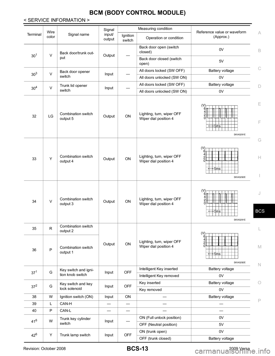
32 LG Combination switch
output 5 Output ONLighting, turn, wiper OFF
Wiper dial position 4
33 Y Combination switch
output 4 Output ON
Lighting, turn, wiper OFF
Wiper dial position 4
34 V Combination switch
output 3 Output ONLighting, turn, wiper OFF
Wiper dial position 4
35 R Combination switch
output 2
Output ONLighting, turn, wiper OFF
Wiper dial position 4
36 P Combination switch
output 1
37 1
GKey switch and igni-
tion knob switch Input OFFIntelligent Key inserted Battery voltage
Intelligent Key removed 0V
37 2
GKey switch and key
lock solenoid Input OFFKey inserted Battery voltage
Key removed 0V
38 W Ignition switch (ON) Input ON — Battery voltage
39 L CAN-H — — — —
40 P CAN-L — — — —
41 6
WTrunk key cylinder
switch Input —ON (Full unlock position) 0V
OFF (Neutral position) 5V
42 6
Y Trunk lamp switch Input OFF ON (trunk open) 0V
OFF (trunk closed) Battery voltage
Terminal
Wire
color Signal name Signal
input/
output Measuring condition
Reference value or waveform
(Approx.)
Ignition
switch Operation or condition SKIA5291E
SKIA5292E
SKIA5291E
SKIA5292E
Page 462 of 4331

BL
N
O P
CONTENTS
BODY, LOCK & SECURITY SYSTEM
SERVICE INFORMATION .. ..........................4
PRECAUTIONS .............................................. .....4
Precaution for Supplemental Restraint System
(SRS) "AIR BAG" and "SEAT BELT PRE-TEN-
SIONER" ............................................................. ......
4
Precaution Necessary fo r Steering Wheel Rota-
tion After Battery Disconnect ............................... ......
4
Precaution for Procedure without Cowl Top Cover ......5
Precaution for Work ............................................ ......5
PREPARATION .............................................. .....6
Special Service Tool ........................................... ......6
Commercial Service Tool .................................... ......6
SQUEAK AND RATTLE TROUBLE DIAG-
NOSES ........................ ........................................7
Work Flow ........................................................... ......7
Generic Squeak and Rattle Troubleshooting ...... ......9
Diagnostic Worksheet ......................................... ....11
HOOD ............................................................. ....13
Fitting Adjustment ............................................... ....13
Removal and Installation .........................................14
Removal and Installation of Hood Lock Control .. ....15
Hood Lock Control Inspec tion .................................17
RADIATOR CORE SUPPORT ....................... ....19
Removal and Installation .........................................19
FRONT FENDER ............................................ ....21
Removal and Installation .........................................21
POWER DOOR LOCK SYSTEM .................... ....22
Component Parts and Harness Connector Loca-
tion ...................................................................... ....
22
System Description ............................................. ....23
CAN Communication System Description ........... ....25
Schematic ........................................................... ....26
Wiring Diagram - D/LOCK - ................................. ....27
Schematic ........................................................... ....31
Wiring Diagram - D/LOCK - ................................. ....32 Terminal and Reference
Value for BCM ..................37
Work Flow ............................................................ ....41
CONSULT-III Function (B CM) .................................41
Trouble Diagnosis Symptom Chart ...................... ....43
BCM Power Supply and Ground Circuit Inspection ....43
Door Switch Check (Hatchback) .......................... ....44
Door Switch Check (Sedan) ................................ ....47
Key Switch (Insert) Check ................................... ....48
Door Lock and Unlock Switch Check .................. ....49
Front Door Lock Assembly LH (Actuator) Check .....52
Door Lock Actuator Check (Front RH and Rear
LH/RH) ................................................................. ....
53
Front Door Key Cylinder S witch LH Check ..............54
Passenger Select Unlock Relay Circuit Inspection
(With Intelligent Key) ........................................... ....
55
REMOTE KEYLESS ENTRY SYSTEM ............. 58
Component Parts and Harness Connector Loca-
tion ....................................................................... ....
58
System Description .............................................. ....58
CAN Communication System Description ........... ....60
Schematic ............................................................ ....61
Wiring Diagram - KEYLES - ................................ ....62
Terminal and Reference Value for BCM ..................65
How to Perform Trouble Diagnosis ...................... ....69
Preliminary Check ............................................... ....69
CONSULT-III Function (B CM) .................................69
Work Flow ............................................................ ....71
Trouble Diagnosis Symptom Chart ...................... ....71
Keyfob Battery and Function Check .................... ....72
ACC Switch Check .............................................. ....74
Door Switch Check (Hatchback) .......................... ....74
Door Switch Check (Sedan) ................................ ....76
Key Switch (Insert) Check ................................... ....78
Hazard Function Check ....................................... ....78
Horn Function Check ........................................... ....79
Interior Lamp and Ignition Keyhole Illumination
Function Check .................................................... ....
79
Remote Keyless Entry Rece iver Check ...................80
Keyfob Function (Lock) Check ............................ ....82
Page 470 of 4331
BL
N
O P
SILICONE GREASE
Used instead of UHMW tape that will be visible or not fit.
Note: Will only last a few months.
SILICONE SPRAY
Use when grease cannot be applied.
DUCT TAPE
Use to eliminate movement.
CONFIRM THE REPAIR Confirm that the cause of a noise is repaired by test driving the vehicle. Operate the vehicle under the same
conditions as when the noise originally occurred. Refer to the notes on the Diagnostic Worksheet.
Generic Squeak and Rattle Troubleshooting INFOID:0000000004304978
Refer to Table of Contents for specific component removal and installation information.
INSTRUMENT PANEL Most incidents are caused by contact and movement between:
1. The cluster lid A and instrument panel
2. Acrylic lens and combination meter housing
3. Instrument panel to front pillar garnish
4. Instrument panel to windshield
5. Instrument panel mounting pins
6. Wiring harnesses behind the combination meter
7. A/C defroster duct and duct joint
These incidents can usually be located by tapping or moving the components to duplicate the noise or by
pressing on the components while driving to stop the noi se. Most of these incidents can be repaired by apply-
ing felt cloth tape or silicone spray (in hard to reach areas). Urethane pads can be used to insulate wiring har-
ness.
CAUTION:
Do not use silicone spray to isolate a squeak or ra ttle. If you saturate the area with silicone, you will
not be able to recheck the repair.
CENTER CONSOLE Components to pay attention to include:
1. Shifter assembly cover to finisher
2. A/C control unit and cluster lid C
3. Wiring harnesses behind audio and A/C control unit
The instrument panel repair and isolation pr ocedures also apply to the center console.
DOORS Pay attention to the:
1. Finisher and inner panel making a slapping noise
2. Inside handle escutcheon to door finisher
3. Wiring harnesses tapping
4. Door striker out of alignment causing a popping noise on starts and stops
Tapping or moving the components or pressing on them wh ile driving to duplicate the conditions can isolate
many of these incidents. You can usually insulate the ar eas with felt cloth tape or insulator foam blocks from
the NISSAN Squeak and Rattle Kit (J-43980) to repair the noise.
TRUNK Trunk noises are often caused by a loose jack or loose items put into the trunk by the owner.
In addition look for:
1. Trunk lid bumpers out of adjustment
2. Trunk lid striker out of adjustment
3. The trunk lid torsion bars knocking together
4. A loose license plate or bracket
Page 476 of 4331
BL
N
O P
Installation
Installation is in the reverse order of removal.
CAUTION:
• Before installing hood hinge, apply anticorrosive agent onto the surfaces that make contact with the
vehicle body.
• After installing, perform hood fitting adjustment. Refer to BL-13, " Fitting Adjustment " .
HOOD HINGE
Removal 1. Remove hood assembly. Refer to BL-14, " Removal and Installation " .
2. Remove front fender. Refer to BL-21, " Removal and Installation " .
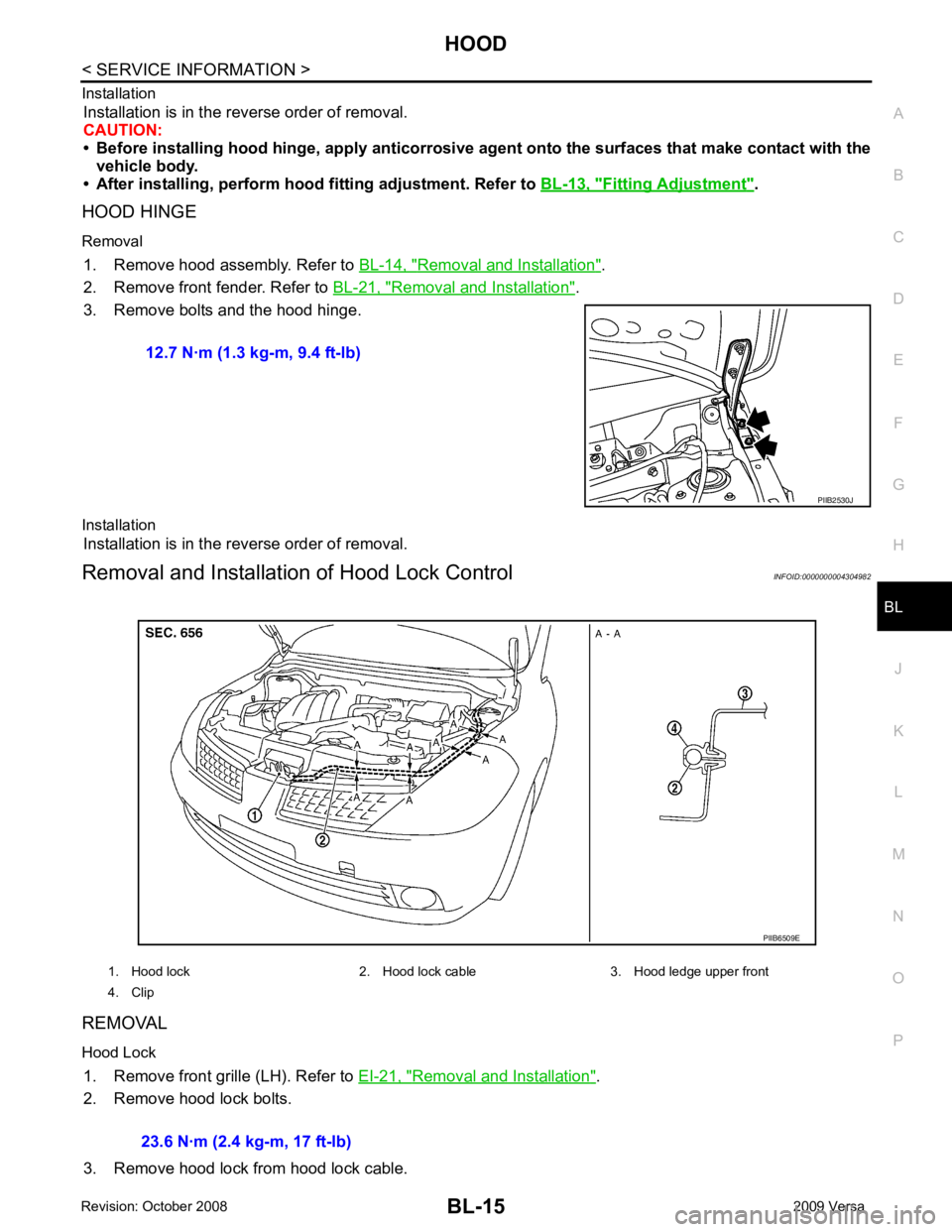
3. Remove bolts and the hood hinge.
Installation Installation is in the reverse order of removal.
Removal and Installation of Hood Lock Control INFOID:0000000004304982
REMOVAL
Hood Lock 1. Remove front grille (LH). Refer to EI-21, " Removal and Installation " .
2. Remove hood lock bolts.
3. Remove hood lock from hood lock cable. 12.7 N·m (1.3 kg-m, 9.4 ft-lb)
Page 478 of 4331
HOOD
BL-17
< SERVICE INFORMATION >
C
D E
F
G H
J
K L
M A
B BL
N
O P
Be careful not to bend the cable too much, keeping the
radius 100 mm (3.94 in) or more.
2. Check that the cable is not of fset from the positioning grommet,
and push the grommet into the panel hole securely.
3. Apply the sealant around the grommet (at * mark).
4. Install cable securely to lock.
5. After installing, check hood lock adjustment and hood opener operation.
Hood Lock Control Inspection INFOID:0000000004304983
CAUTION:
If the hood lock cable is bent or deformed, replace it.
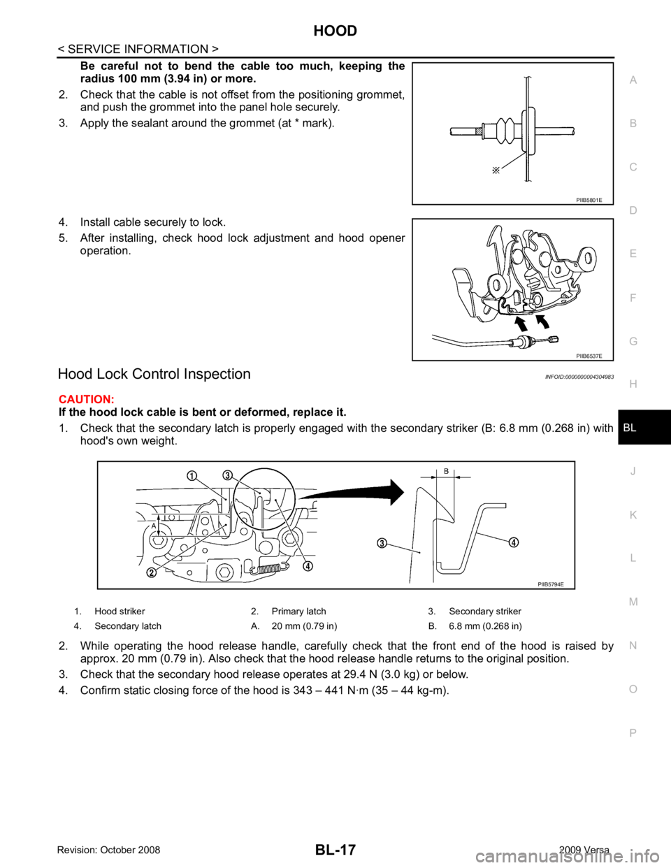
1. Check that the secondary latch is properly engaged with the secondary striker (B: 6.8 mm (0.268 in) with
hood's own weight.
2. While operating the hood release handle, carefully check that the front end of the hood is raised by
approx. 20 mm (0.79 in). Also check that the hood release handle returns to the original position.
3. Check that the secondary hood release operates at 29.4 N (3.0 kg) or below.
4. Confirm static closing force of the hood is 343 – 441 N·m (35 – 44 kg-m). PIIB5801E
PIIB6537E
1. Hood striker 2. Primary
latch 3. Secondary striker
4. Secondary latch A. 20 mm (0.79 in) B. 6.8 mm (0.268 in) PIIB5794E
Page 499 of 4331
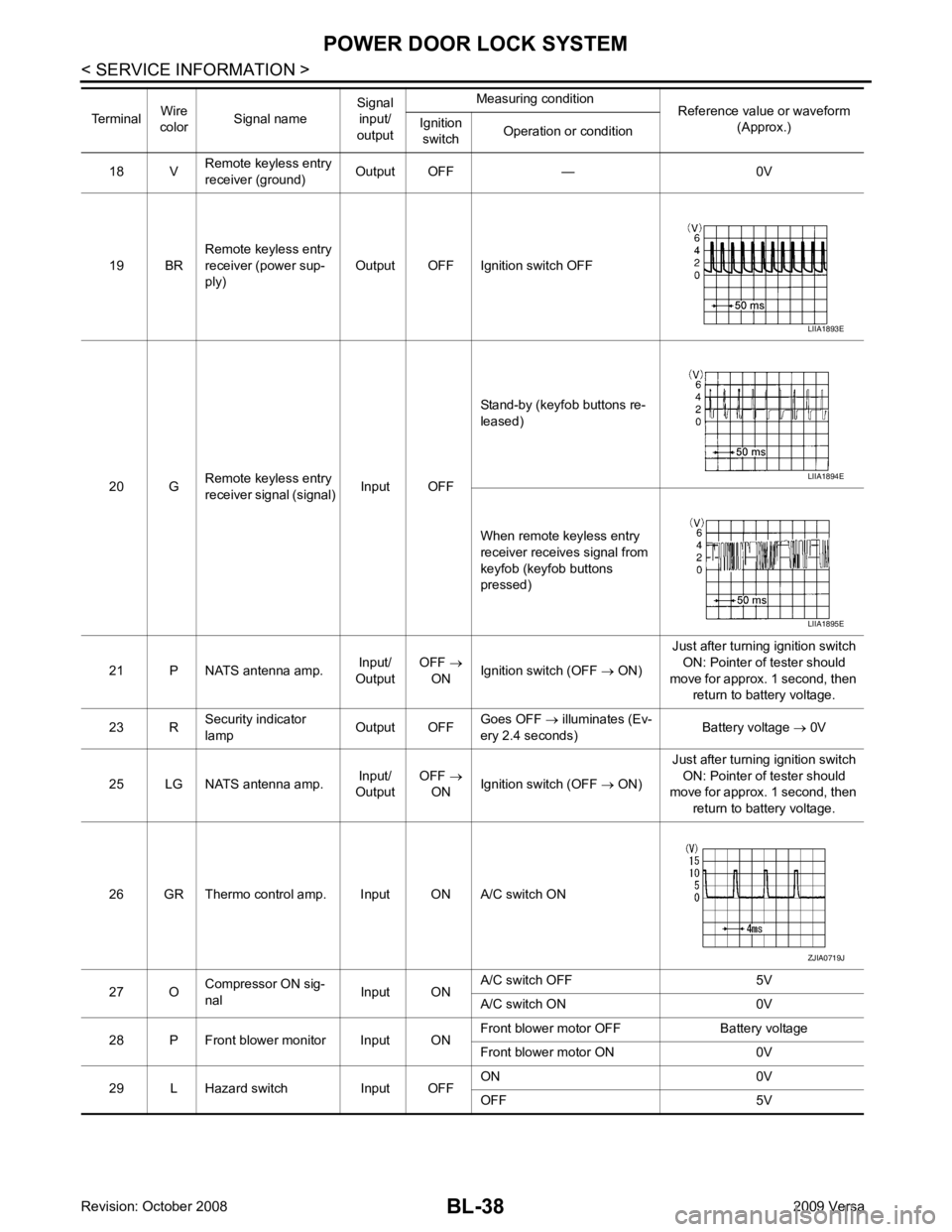
BL-38< SERVICE INFORMATION >
POWER DOOR LOCK SYSTEM
18 V Remote keyless entry
receiver (ground) Output OFF — 0V
19 BR Remote keyless entry
receiver (power sup-
ply) Output OFF Ignition switch OFF
20 G Remote keyless entry
receiver signal (signal) Input OFFStand-by (keyfob buttons re-
leased)
When remote keyless entry
receiver receives signal from
keyfob (keyfob buttons
pressed)
21 P NATS antenna amp. Input/
Output OFF
→
ON Ignition switch (OFF
→ ON) Just after turning ignition switch
ON: Pointer of tester should
move for approx. 1 second, then return to battery voltage.
23 R Security indicator
lamp Output OFFGoes OFF
→ illuminates (Ev-
ery 2.4 seconds) Battery voltage
→ 0V
25 LG NATS antenna amp. Input/
Output OFF
→
ON Ignition switch (OFF
→ ON) Just after turning ignition switch
ON: Pointer of tester should
move for approx. 1 second, then
return to battery voltage.
26 GR Thermo control amp. Input ON A/C switch ON
27 O Compressor ON sig-
nal Input ONA/C switch OFF 5V
A/C switch ON 0V
28 P Front blower monitor Input ON Front blower motor OFF Battery voltage
Front blower motor ON 0V
29 L Hazard switch Input OFF ON 0V
OFF 5V
Terminal
Wire
color Signal name Signal
input/
output Measuring condition
Reference value or waveform
(Approx.)
Ignition
switch Operation or condition LIIA1893E
LIIA1894E
LIIA1895E
ZJIA0719J
Page 520 of 4331
![NISSAN TIIDA 2009 Service Repair Manual BL
N
O P
• through 10A fuse [No. 14, located in the fuse block (J/B)]
• through key switch terminals 2 and 1
• to BCM terminal 37.
When the ignition switch is ACC or ON, power is supplied
• th NISSAN TIIDA 2009 Service Repair Manual BL
N
O P
• through 10A fuse [No. 14, located in the fuse block (J/B)]
• through key switch terminals 2 and 1
• to BCM terminal 37.
When the ignition switch is ACC or ON, power is supplied
• th](/manual-img/5/57398/w960_57398-519.png)
BL
N
O P
• through 10A fuse [No. 14, located in the fuse block (J/B)]
• through key switch terminals 2 and 1
• to BCM terminal 37.
When the ignition switch is ACC or ON, power is supplied
• through 10A fuse [No. 20, located in the fuse block (J/B)]
• to BCM terminal 11.
Ground is supplied
• to BCM terminal 67
• through body grounds M57 and M61.
When the front door switch LH is ON (door is OPEN), ground is supplied
• to BCM terminal 47
• through front door switch LH terminal 2
• through front door switch LH case ground.
When the front door switch RH is ON (door is OPEN), ground is supplied
• to BCM terminal 12
• through front door switch RH terminal 2
• through front door switch RH case ground.
When the rear door switch LH is ON (door is OPEN), ground is supplied
• to BCM terminal 48
• through rear door switch LH terminal 1
• through rear door switch LH case ground.
When the rear door switch RH is ON (door is OPEN), ground is supplied
• to BCM meter terminal 13
• through rear door switch RH terminal 1
• through rear door switch RH case ground.
When the back door lock assembly (back door switch) (hat chback) is ON (back door is OPEN), ground is sup-
plied
• to BCM terminal 43
• through back door lock assembly (back door switch) terminals 3 and 4
• through body grounds B117, B132 and D402.
Keyfob signal is inputted to BCM from remote keyless entry receiver.
The remote keyless entry system controls operation of the
• power door lock
• hazard reminder
• auto door lock
• panic alarm
• room lamp
OPERATED PROCEDURE
Power Door Lock Operation BCM receives a LOCK signal from keyfob. BCM lock s all doors with input of LOCK signal from keyfob.
BCM receives a UNLOCK signal from keyfob. BCM unlocks all doors with input of UNLOCK signal from key-
fob.
Hazard and Horn Reminder When the doors are locked or unlocked by keyfob, power is supplied to sound horn and flash hazard warning
lamps as follows
• LOCK operation: 3 or 4 mode (lamps flash twice)
• UNLOCK operation: 2 or 4 mode (lamps flash once)
• Horn sounds once with LOCK function when this feature is set ON.
The hazard reminder has modes 1, 2, 3 or 4. The hor n reminder can be turned ON/OFF with any LOCK mode.
Operating function of hazard reminder
Hazard and horn reminders do not operate if any door switch is ON (any door is OPEN).
How to change hazard and horn reminder modes Mode 1 Mode 2 Mode 3 Mode 4
Keyfob operation Lock Unlock Lock Unlock Lock Unlock Lock Unlock
Hazard warning lamp
flash — — — Twice Once — Once Twice
Horn sound (ON/OFF) ON: once — O N: once — ON: once — ON: once —
Page 527 of 4331
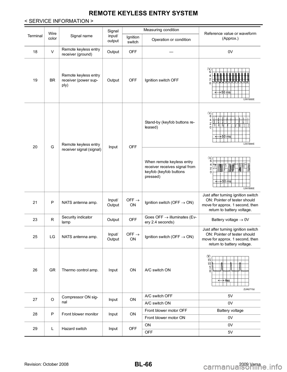
BL-66< SERVICE INFORMATION >
REMOTE KEYLESS ENTRY SYSTEM
18 V Remote keyless entry
receiver (ground) Output OFF — 0V
19 BR Remote keyless entry
receiver (power sup-
ply) Output OFF Ignition switch OFF
20 G Remote keyless entry
receiver signal (signal) Input OFFStand-by (keyfob buttons re-
leased)
When remote keyless entry
receiver receives signal from
keyfob (keyfob buttons
pressed)
21 P NATS antenna amp. Input/
Output OFF
→
ON Ignition switch (OFF
→ ON) Just after turning ignition switch
ON: Pointer of tester should
move for approx. 1 second, then return to battery voltage.
23 R Security indicator
lamp Output OFFGoes OFF
→ illuminates (Ev-
ery 2.4 seconds) Battery voltage
→ 0V
25 LG NATS antenna amp. Input/
Output OFF
→
ON Ignition switch (OFF
→ ON) Just after turning ignition switch
ON: Pointer of tester should
move for approx. 1 second, then
return to battery voltage.
26 GR Thermo control amp. Input ON A/C switch ON
27 O Compressor ON sig-
nal Input ONA/C switch OFF 5V
A/C switch ON 0V
28 P Front blower monitor Input ON Front blower motor OFF Battery voltage
Front blower motor ON 0V
29 L Hazard switch Input OFF ON 0V
OFF 5V
Terminal
Wire
color Signal name Signal
input/
output Measuring condition
Reference value or waveform
(Approx.)
Ignition
switch Operation or condition LIIA1893E
LIIA1894E
LIIA1895E
ZJIA0719J