2009 NISSAN TIIDA e control
[x] Cancel search: e controlPage 714 of 4331
NATS (NISSAN ANTI-THEFT SYSTEM)
BL-253
< SERVICE INFORMATION >
C
D E
F
G H
J
K L
M A
B BL
N
O P
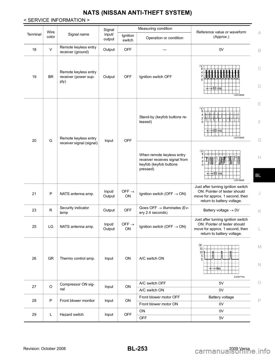
18 V
Remote keyless entry
receiver (ground) Output OFF — 0V
19 BR Remote keyless entry
receiver (power sup-
ply) Output OFF Ignition switch OFF
20 G Remote keyless entry
receiver signal (signal) Input OFFStand-by (keyfob buttons re-
leased)
When remote keyless entry
receiver receives signal from
keyfob (keyfob buttons
pressed)
21 P NATS antenna amp. Input/
Output OFF
→
ON Ignition switch (OFF
→ ON) Just after turning ignition switch
ON: Pointer of tester should
move for approx. 1 second, then return to battery voltage.
23 R Security indicator
lamp Output OFFGoes OFF
→ illuminates (Ev-
ery 2.4 seconds) Battery voltage
→ 0V
25 LG NATS antenna amp. Input/
Output OFF
→
ON Ignition switch (OFF
→ ON) Just after turning ignition switch
ON: Pointer of tester should
move for approx. 1 second, then
return to battery voltage.
26 GR Thermo control amp. Input ON A/C switch ON
27 O Compressor ON sig-
nal Input ONA/C switch OFF 5V
A/C switch ON 0V
28 P Front blower monitor Input ON Front blower motor OFF Battery voltage
Front blower motor ON 0V
29 L Hazard switch Input OFF ON 0V
OFF 5V
Terminal
Wire
color Signal name Signal
input/
output Measuring condition
Reference value or waveform
(Approx.)
Ignition
switch Operation or condition LIIA1893E
LIIA1894E
LIIA1895E
ZJIA0719J
Page 720 of 4331
BL
N
O P
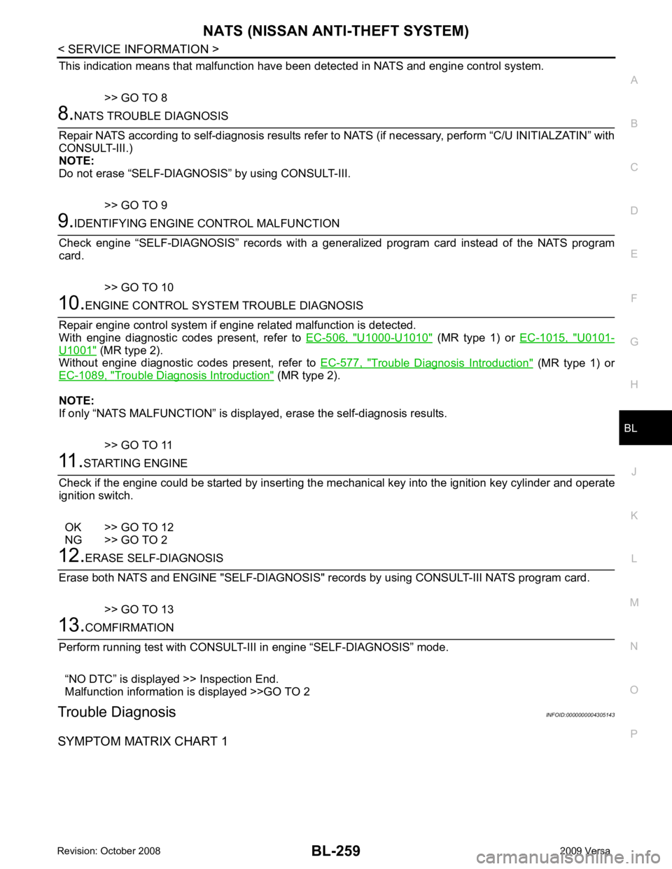
This indication means that malfunction have been
detected in NATS and engine control system.
>> GO TO 8 U1000-U1010 " (MR type 1) or
EC-1015, " U0101-
U1001 " (MR type 2).
Without engine diagnostic codes present, refer to EC-577, " Trouble Diagnosis Introduction " (MR type 1) or
EC-1089, " Trouble Diagnosis Introduction " (MR type 2).
NOTE:
If only “NATS MALFUNCTION” is display ed, erase the self-diagnosis results.
>> GO TO 11
Page 803 of 4331

BR
N
O P
5. When the repair work is completed, return the ignition switch to the
″LOCK ″ position before connecting
the battery cables. (At this time, the steering lock mechanism will engage.)
6. Perform a self-diagnosis check of al l control units using CONSULT-III.
Precaution for Brake System INFOID:0000000004305887
• Refill using recommended brake fluid. Refer to MA-14 .
• Never reuse drained brake fluid.
• Be careful not to splash brake fluid on painted surfac e of body. If brake fluid is splashed on painted surfaces
of body immediately wipe it off with cloth and then wash it away with water.
• To clean or wash all parts of master cylinder, disc brake caliper and wheel cylinder, use new brake fluid.
• Never use mineral oils such as gasoline or kerosene. They will ruin rubber parts of the hydraulic system.
• Use a flare nut wrench when removing a brake tube and use a flare nut torque wrench when installing a brake tube.
• When installing brake tubes and hoses, be sure to check torque.
• Before working, turn igniti on switch OFF and disconnect connec-
tors of ABS actuator and electric unit (control unit) or the battery
cable from the negative terminal.
• Burnish the new braking surfaces after refinishing or replacing drums or rotors, after replacing p ads or linings, or if a soft pedal
occurs at very low mileage. Refer to BR-32, " Brake Burnishing
Procedure " .
Page 809 of 4331
BR
N
O P
BRAKE FLUID
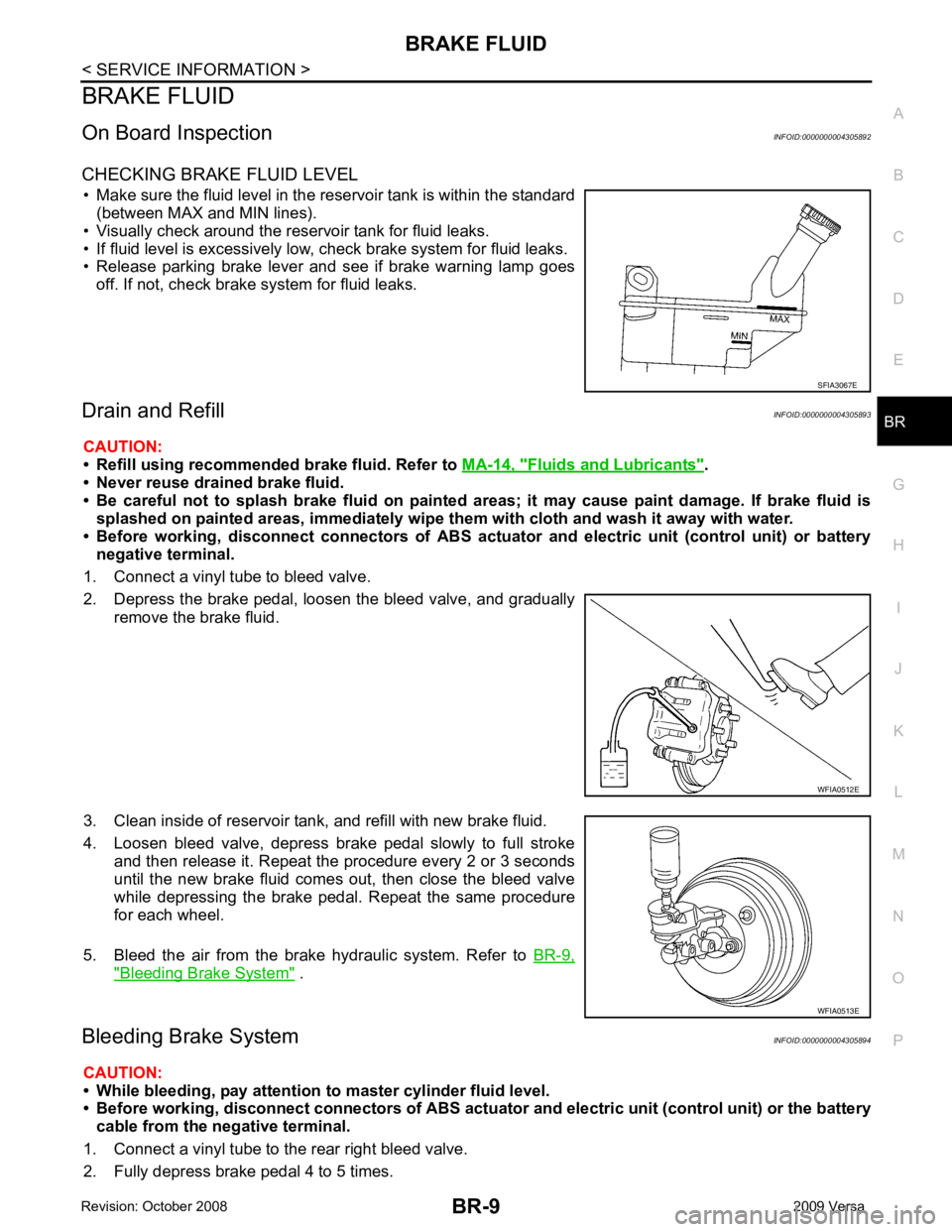
On Board Inspection INFOID:0000000004305892
CHECKING BRAKE FLUID LEVEL • Make sure the fluid level in the reservoir tank is within the standard (between MAX and MIN lines).
• Visually check around the reservoir tank for fluid leaks.
• If fluid level is excessively low, check brake system for fluid leaks.
• Release parking brake lever and see if brake warning lamp goes
off. If not, check brake system for fluid leaks.
Drain and Refill INFOID:0000000004305893
CAUTION:
• Refill using recommended brake fluid. Refer to MA-14, " Fluids and Lubricants " .
• Never reuse drained brake fluid.
• Be careful not to splash brake fluid on painted areas; it may cause paint damage. If brake fluid is
splashed on painted areas, immediately wipe th em with cloth and wash it away with water.
• Before working, disconnect connect ors of ABS actuator and electric unit (control unit) or battery
negative terminal.
1. Connect a vinyl tube to bleed valve.
2. Depress the brake pedal, loosen the bleed valve, and gradually remove the brake fluid.
3. Clean inside of reservoir tank, and refill with new brake fluid.
4. Loosen bleed valve, depress brake pedal slowly to full stroke and then release it. Repeat the procedure every 2 or 3 seconds
until the new brake fluid comes out, then close the bleed valve
while depressing the brake pedal . Repeat the same procedure
for each wheel.
5. Bleed the air from the brake hydraulic system. Refer to BR-9," Bleeding Brake System " .
Bleeding Brake System INFOID:0000000004305894
CAUTION:
• While bleeding, pay attention to master cylinder fluid level.
• Before working, disconnect connectors of ABS actuator and electri c unit (control unit) or the battery
cable from the negative terminal.
1. Connect a vinyl tube to the rear right bleed valve.
2. Fully depress brake pedal 4 to 5 times.
Page 841 of 4331

BRC
N
O P
CONTENTS
BRAKE CONTROL SYSTEM
ABS
SERVICE INFORMATION .. ..........................
2
PRECAUTIONS .............................................. .....2
Precaution for Supplemental Restraint System
(SRS) "AIR BAG" and "SEAT BELT PRE-TEN-
SIONER" ............................................................. ......
2
Precaution for Brake System .............................. ......2
Precaution for Brake Cont rol .....................................3
Precaution for CAN System ................................ ......3
PREPARATION .............................................. .....4
Special Service Tool ........................................... ......4
Commercial Service Tool .................................... ......4
SYSTEM DESCRIPTION ................................ .....5
System Component ............................................. ......5
ABS Function ...................................................... ......5
EBD Function ...................................................... ......5
Fail-Safe Function ............................................... ......5
Hydraulic Circuit Diagram .........................................6
CAN COMMUNICATION ................................ .....7
System Description ............................................. ......7
TROUBLE DIAGNOSIS ................................. .....8
How to Perform Trouble Diagnosis for Quick and
Accurate Repair ........... .............................................
8
Component Parts and Harness Connector Loca-
tion ...................................................................... ....
11
Schematic ........................................................... ....12
Wiring Diagram - ABS - ... ........................................13 Basic Inspection ..................................................
....16
Warning Lamp and Indicator Timing .................... ....17
Control Unit Input/Output Signal Standard .......... ....17
CONSULT-III Function ( ABS) ..................................18
TROUBLE DIAGNOSIS FOR SELF-DIAG-
NOSTIC ITEMS ................................................. 24
Wheel Sensor System ......................................... ....24
ABS Control Unit Inspection ................................ ....25
Solenoid Valve System Inspection ...................... ....25
Actuator Motor, Motor Re lay, and Circuit Inspec-
tion ....................................................................... ....
26
ABS Control Unit Power and Ground Systems In-
spection ............................................................... ....
27
CAN Communication System Inspection ............. ....28
TROUBLE DIAGNOSES FOR SYMPTOMS ..... 29
ABS Works Frequently ........................................ ....29
Unexpected Pedal Action .................................... ....29
Long Stopping Distance ...................................... ....30
ABS Does Not Work ............................................ ....30
Pedal Vibration or ABS Op eration Noise .................30
WHEEL SENSORS ........................................... 32
Removal and Installation ..................................... ....32
SENSOR ROTOR .............................................. 34
Removal and Installation ..................................... ....34
ACTUATOR AND ELECTRIC UNIT (ASSEM-
BLY) .................................................................. 35
Removal and Installation ..................................... ....35
Page 843 of 4331
BRC
N
O P
Precaution for Brake Control
INFOID:0000000004307252
• During ABS operation, the brake pedal may vibrate lightly and a mechanical noise may be heard. This is normal.
• Just after starting the vehicle, the brake pedal may vibrate or motor operating noises may be heard from
engine compartment. This is normal due to the self check operation.
• Stopping distance may be longer than that of vehicles without ABS when vehicle drives on rough, gravel, or
snow-covered (fresh, deep snow) roads.
• When an error is indicated by ABS or another warning lamp, collect all necessary information from customer
(what symptoms are present under what conditions) and check for simple causes before starting diagnosis.
Besides electrical system inspection, check brake booster operation, brake fluid level, and fluid leaks.
• If incorrect tire sizes or types are installed on the vehicle or brake pads are not Genuine NISSAN parts, stop-
ping distance or steering stability may deteriorate.
• If there is a radio, antenna or related wiring near t he control module, ABS function may have a malfunction
or error.
• If aftermarket parts (car stereo, CD player, etc.) have been installed, check for incidents such as harness pinches, open circuits or improper wiring.
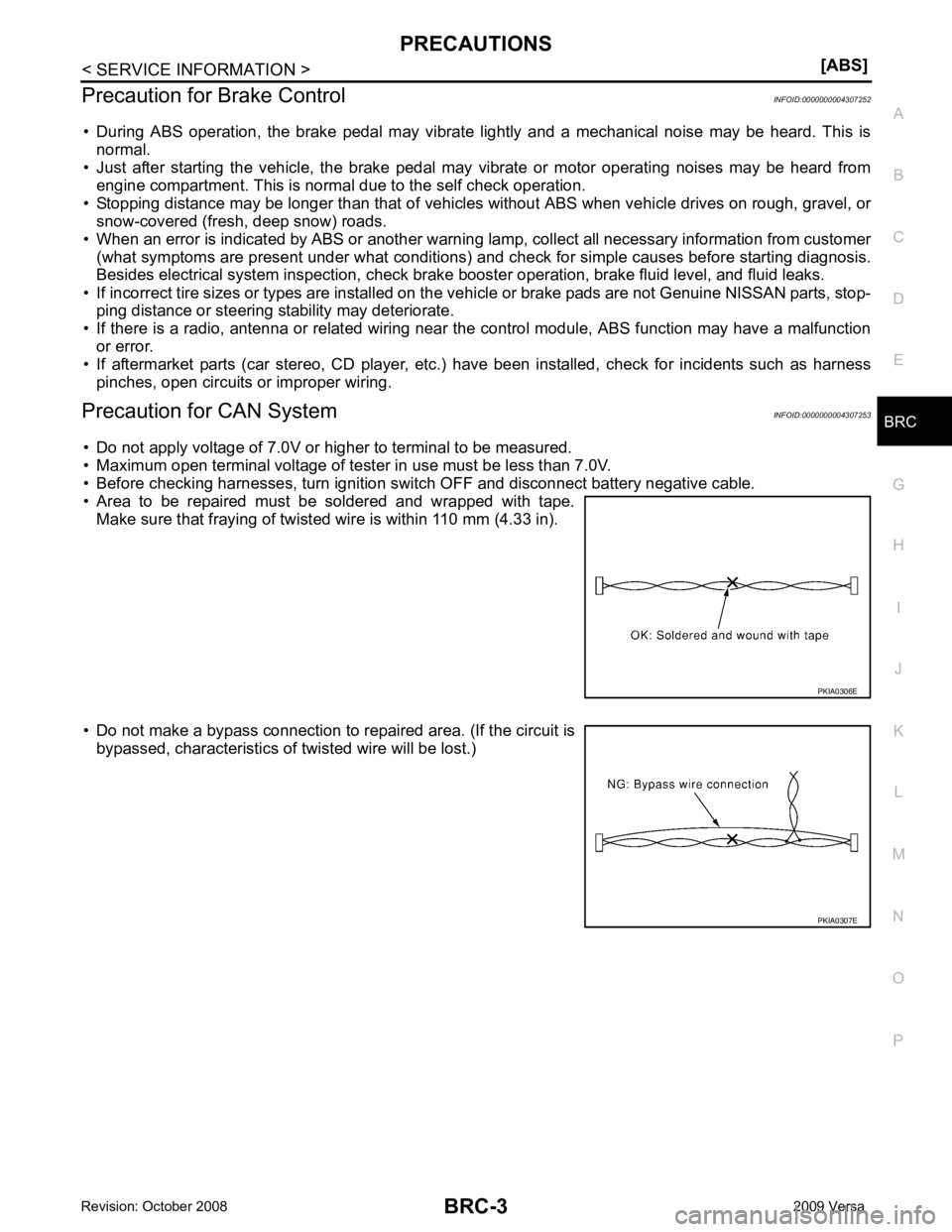
Precaution for CAN System INFOID:0000000004307253
• Do not apply voltage of 7.0V or higher to terminal to be measured.
• Maximum open terminal voltage of tester in use must be less than 7.0V.
• Before checking harnesses, turn ignition switch OFF and disconnect battery negative cable.
• Area to be repaired must be soldered and wrapped with tape. Make sure that fraying of twisted wire is within 110 mm (4.33 in).
• Do not make a bypass connection to repaired area. (If the circuit is bypassed, characteristics of twisted wire will be lost.)
Page 845 of 4331
BRC
N
O P
SYSTEM DESCRIPTION
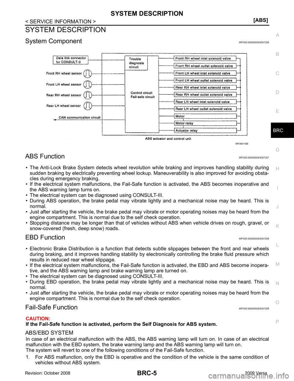
System Component INFOID:0000000004307256
ABS Function INFOID:0000000004307257
• The Anti-Lock Brake System detects wheel revolution while braking and improves handling stability during sudden braking by electrically preventing wheel lockup. Maneuverability is also improved for avoiding obsta-
cles during emergency braking.
• If the electrical system malfunctions, the Fail-Safe function is activated, the ABS becomes inoperative and
the ABS warning lamp turns on.
• The electrical system can be diagnosed using CONSULT-III.
• During ABS operation, the brake pedal may vibrate lightly and a mechanical noise may be heard. This is
normal.
• Just after starting the vehicle, the brake pedal may vibrate or motor operating noises may be heard from the
engine compartment. This is normal due to the self check operation.
• Stopping distance may be longer than that of vehicles without ABS when vehicle drives on rough, gravel, or
snow-covered (fresh, deep snow) roads.
EBD Function INFOID:0000000004307258
• Electronic Brake Distribution is a function that detec ts subtle slippages between the front and rear wheels
during braking, and it improves handling stability by elec tronically controlling the brake fluid pressure which
results in reduced rear wheel slippage.
• If the electrical system malfunctions, the Fail-Safe function is activated, the EBD and ABS become inopera-
tive, and the ABS warning lamp and brake warning lamp are turned on.
• The electrical system can be diagnosed using CONSULT-III.
• During EBD operation, the brake pedal may vibrate lightly and a mechanical noise may be heard. This is
normal.
• Just after starting the vehicle, the brake pedal may vibrate or motor operating noises may be heard from the
engine compartment. This is normal due to the self check operation.
Fail-Safe Function INFOID:0000000004307259
CAUTION:
If the Fail-Safe function is activated, perform the Self Diagnosis for ABS system.
ABS/EBD SYSTEM In case of an electrical malfunction with the ABS, the ABS warning lamp wi ll turn on. In case of an electrical
malfunction with the EBD system, the brake warni ng lamp and the ABS warning lamp will turn on.
The system will revert to one of the follo wing conditions of the Fail-Safe function.
1. For ABS malfunction, only the EBD is operative and t he condition of the vehicle is the same condition of
vehicles without ABS system.
Page 857 of 4331
BRC
N
O P
• If ABS actuator and electric unit (control unit) connec
tion is loose, tighten the piping to the specified
torque and recheck for leaks.
• If there is damage to the connection flare nut or A BS actuator and electric unit (control unit) threads,
replace the damaged part and recheck for leaks.
• When there is fluid leaking or seeping from a fluid connection, use a clean cloth to wipe off the fluid and recheck for leaks. If fluid is still seeping out, repl ace the damaged part. If the fluid is leaking at the ABS
actuator and electric unit (control unit), replace the ABS actuator and electric unit (control unit) assem-
bly.
CAUTION:
The ABS actuator and electric unit (control un it) cannot be disassembled and must be replaced
as an assembly.
3. Check the brake pads for excessive wear.
POWER SYSTEM TERMINAL LOOSENESS AND BATTERY INSPECTION Make sure the battery positive cable, negative cabl e and ground connection are not loose. In addition, make
sure the battery is sufficiently charged.
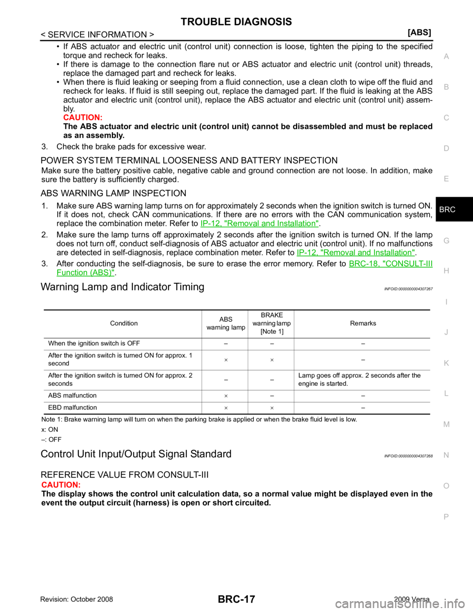
ABS WARNING LAMP INSPECTION 1. Make sure ABS warning lamp turns on for approximately 2 seconds when the ignition switch is turned ON. If it does not, check CAN communications. If ther e are no errors with the CAN communication system,
replace the combination meter. Refer to IP-12, " Removal and Installation " .
2. Make sure the lamp turns off approximately 2 seconds after the ignition switch is turned ON. If the lamp does not turn off, conduct self-diagnosis of ABS act uator and electric unit (control unit). If no malfunctions
are detected in self-diagnosis, replace combination meter. Refer to IP-12, " Removal and Installation " .
3. After conducting the self-diagnosis, be sure to erase the error memory. Refer to BRC-18, " CONSULT-III
Function (ABS) " .
Warning Lamp and Indicator Timing INFOID:0000000004307267
Note 1: Brake warning lamp will turn on when the parking brake is applied or when the brake fluid level is low.
x: ON
–: OFF
Control Unit Input/Out put Signal Standard INFOID:0000000004307268
REFERENCE VALUE FROM CONSULT-III CAUTION:
The display shows the control unit calculation data, so a normal value might be displayed even in the
event the output circuit (harness) is open or short circuited.
Condition
ABS
warning lamp BRAKE
warning lamp [Note 1] Remarks
When the ignition switch is OFF – – –
After the ignition switch is turned ON for approx. 1
second × ×
–
After the ignition switch is turned ON for approx. 2
seconds – –Lamp goes off approx. 2 seconds after the
engine is started.
ABS malfunction ×– –
EBD malfunction × ×–