2009 NISSAN TIIDA e control
[x] Cancel search: e controlPage 930 of 4331
![NISSAN TIIDA 2009 Service Repair Manual CO-36< SERVICE INFORMATION >
[MR18DE]
ENGINE COOLANT
REFILLING ENGINE COOLANT
1. Install the radiator drain plug. Install the reservoir tank and cylinder block drain plug, if removed for a total
syst NISSAN TIIDA 2009 Service Repair Manual CO-36< SERVICE INFORMATION >
[MR18DE]
ENGINE COOLANT
REFILLING ENGINE COOLANT
1. Install the radiator drain plug. Install the reservoir tank and cylinder block drain plug, if removed for a total
syst](/manual-img/5/57398/w960_57398-929.png)
CO-36< SERVICE INFORMATION >
[MR18DE]
ENGINE COOLANT
REFILLING ENGINE COOLANT
1. Install the radiator drain plug. Install the reservoir tank and cylinder block drain plug, if removed for a total
system drain or for engine removal or repair.
• The radiator must be complete ly empty of coolant and water.
• Apply sealant to the threads of the cylinder bl ock drain plugs. Use Genuine High Performance
Thread Sealant or equivalent. Refer to GI-42, " Recommended Chemical Product and Sealant " .
2. If disconnected, reattach the upper radiator hose at the engine side.
3. Set the vehicle heater controls to the full HOT and heat er ON position. Turn the vehicle ignition ON with
the engine OFF as necessary to activate the heater mode.
4. Install the Tool by installing the radiator cap adapter onto the radiator neck opening. Then attach the gauge body assembly
with the refill tube and the venturi assembly to the radiator cap
adapter.
5. Insert the refill hose into the coolant mixture container that is placed at floor level. Make sure the ball valve is in the closed
position.
• Use Genuine NISSAN Long Life Anti-freeze coolant or
equivalent, mixed with distil led water or demineralized
water.
Refer to MA-15, " Anti-freeze Coolant Mixture Ratio " .
6. Install an air hose to the venturi assembly, the air pressure must be within specification.
CAUTION:
The compressed air supply must be equipped with an air dryer.
7. The vacuum gauge will begin to rise and there will be an audible hissing noise. During this process open the ball valve on the refill hose slightly. Coolant will be vi sible rising in the refill hose. Once the refill hose is
full of coolant, close the ball valve. This will purge any air trapped in the refill hose.
8. Continue to draw the vacuum until the gauge reaches 28 inches of vacuum. The gauge may not reach 28 inches in high altitude
locations, use the vacuum specifications based on the altitude
above sea level.
9. When the vacuum gauge has reached the specifi ed amount, disconnect the air hose and wait 20 seconds
to see if the system loses any vacuum. If the vacuum level drops, perform any necessary repairs to the
system and repeat steps 6 - 8 to bring the vacuum to the specified amount. Recheck for any leaks.
Radiator drain plug : Refer to
CO-38, " Component " .
Cylinder block drain plug : Refer to EM-200, " Disassembly and Assembly " .
Tool number : KV991J0070 (J-45695)
Engine coolant capacity
(with reservoir tank) : Refer to
MA-14, " Fluids
and Lubricants " .
Compressed air
supply pressure : 5.7 - 8.5 kPa (5.6 - 8.4 kg/cm
2
,
80 - 120 psi) LLIA0058E
Altitude above sea level Vacuum gauge reading
0 - 100 m (328 ft) : 28 inches of vacuum
300 m (984 ft) : 27 inches of vacuum
500 m (1,641 ft) : 26 inches of vacuum
1,000 m (3,281 ft) : 24 - 25 inches of vacuum LLIA0057E
Page 935 of 4331
![NISSAN TIIDA 2009 Service Repair Manual COOLING FAN
CO-41
< SERVICE INFORMATION >
[MR18DE] C
D E
F
G H
I
J
K L
M A CO
NP
O
COOLING FAN
Component (Models with A/C) INFOID:0000000004305240
Component (Models without A/C) INFOID:000000000430524 NISSAN TIIDA 2009 Service Repair Manual COOLING FAN
CO-41
< SERVICE INFORMATION >
[MR18DE] C
D E
F
G H
I
J
K L
M A CO
NP
O
COOLING FAN
Component (Models with A/C) INFOID:0000000004305240
Component (Models without A/C) INFOID:000000000430524](/manual-img/5/57398/w960_57398-934.png)
COOLING FAN
CO-41
< SERVICE INFORMATION >
[MR18DE] C
D E
F
G H
I
J
K L
M A CO
NP
O
COOLING FAN
Component (Models with A/C) INFOID:0000000004305240
Component (Models without A/C) INFOID:0000000004305241
1. Fan motor cover 2. Fan motor 3. Cooling fan control module
4. Washer 5. Fan shroud 6. Washer
7. Cooling fan A. Apply on fan motor shaft Front PBIC4538E
1. Fan motor 2. Fan shroud 3. Cooling fan
A. Apply on fan motor shaft Front WBIA0786E
Page 936 of 4331
Changing Engine Coolant " .
CAUTION:
• Perform this step when engine is cold.
• Do not spill engine coolant on drive belt.
2. Remove air duct (inlet). Refer to EM-139, " Component " .
3. Remove reservoir tank. Refer to CO-38, " Component " .
4. Disconnect radiator hose (upper) at radiator side. Refer to CO-38, " Component " .
5. Disconnect harness connectors from fan motor, and move harness aside.
6. Remove cooling fan assembly. CAUTION:
Be careful not to damage or scratch the radiator core.
INSTALLATION
Installation is in the reverse order of removal.
• Cooling fans are controlled by ECM. For details, refer to EC-886, " System Description " .
CAUTION:
Be careful not to damage or scratch the radiator core.
Disassembly and Assembly INFOID:0000000004305243
DISASSEMBLY
1. Remove cooling fan from fan motor.
2. Remove fan motor from fan shroud.
INSPECTION AFTER DISASSEMBLY
Inspect cooling fan for crack or unusual bend.
• If anything is found, replace cooling fan.
ASSEMBLY
Assembly is in the reverse order of disassembly.
Page 941 of 4331
CO
NP
O
WATER OUTLET AND WATER CONTROL VALVE
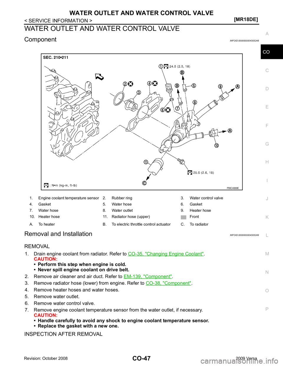
Component INFOID:0000000004305248
Removal and Installation INFOID:0000000004305249
REMOVAL 1. Drain engine coolant from radiator. Refer to CO-35, " Changing Engine Coolant " .
CAUTION:
• Perform this step when engine is cold.
• Never spill engine coolant on drive belt.
2. Remove air cleaner and air duct. Refer to EM-139, " Component " .
3. Remove radiator hose (lower) from engine. Refer to CO-38, " Component " .
4. Remove heater hoses and water hoses.
5. Remove water outlet.
6. Remove water control valve.
7. Remove engine coolant temperature sensor from the water outlet, if necessary. CAUTION:
• Handle carefully to avoid any shock to engine coolant temperature sensor.
• Replace the gasket with a new one.
INSPECTION AFTER REMOVAL 1. Engine coolant temperature sensor 2. Rubber ring 3. Water control valve
4. Gasket 5. Water hose 6. Gasket
7. Water hose 8. Water outlet 9. Heater hose
10. Heater hose 11. Radiator hose (upper) Front
A. To heater B. To electric throttle control actuator C. To radiator
Page 942 of 4331
![NISSAN TIIDA 2009 Service Repair Manual CO-48< SERVICE INFORMATION >
[MR18DE]
WATER OUTLET AND WATER CONTROL VALVE
• Place a thread (A) so that it is c aught in the valves of water control
valve (1). Immerse fully in a container (B NISSAN TIIDA 2009 Service Repair Manual CO-48< SERVICE INFORMATION >
[MR18DE]
WATER OUTLET AND WATER CONTROL VALVE
• Place a thread (A) so that it is c aught in the valves of water control
valve (1). Immerse fully in a container (B](/manual-img/5/57398/w960_57398-941.png)
CO-48< SERVICE INFORMATION >
[MR18DE]
WATER OUTLET AND WATER CONTROL VALVE
• Place a thread (A) so that it is c aught in the valves of water control
valve (1). Immerse fully in a container (B) filled with water. Heat
while stirring.
• The valve opening temperature is the temperature at which the
valve opens and falls from the thread.
• Continue heating. Check the full-open valve lift amount.
NOTE:
The full-open valve lift amount standard temperature for water con-
trol valve is the reference value.
• After checking the full-open valve lift amount, lower the water tem- perature and check the valve closing temperature.
• If out of the specification, replace water control valve.
INSTALLATION
Installation is in the reverse order of removal.
• Use the following procedure to install the water control valve.
- Install water control valve while making rubber ring (1) groove fit to water control valve flange (A) around the whole circumference.
CAUTION:
Replace the rubber ring with a new one.
- While the mark (A) points to up, install water control valve (2) with frame center (B) facing straight upward into water outlet (1).
• Use the following procedure to install the water outlet.
- Install the water outlet to the cylinder head without disp lacing the water control valve from the valve position.
• Use the following procedure to install the water hoses. Valve opening temperature 93.5 - 96.5
°C (200 - 206 °F)
Full-open valve lift amount 8 mm/ 108 °C (0.315 in/ 226 °F)
Valve closing temperature 90 °C (194 °F) PBIC3314J
PBIC3317J
PBIC4700E
Page 943 of 4331
CO
NP
O
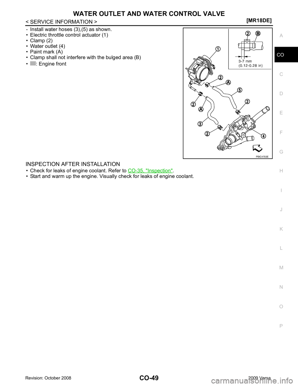
- Install water hoses (3),(5) as shown.
• Electric throttle control actuator (1)
• Clamp (2)
• Water outlet (4)
• Paint mark (A)
• Clamp shall not interfere with the bulged area (B)
• : Engine front
INSPECTION AFTER INSTALLATION • Check for leaks of engine coolant. Refer to CO-35, " Inspection " .
• Start and warm up the engine. Visually check for leaks of engine coolant.
Page 945 of 4331
CVT
N
O P
CONTENTS
CVT
RE0F08A
SERVICE INFORMATION .. ..........................
9
INDEX FOR DTC ............................................ .....9
Alphabetical Index ............................................... ......9
DTC No. Index .................................................... ......9
PRECAUTIONS .............................................. ....11
Precaution for Supplemental Restraint System
(SRS) "AIR BAG" and "SEAT BELT PRE-TEN-
SIONER" ............................................................. ....
11
Precaution Necessary fo r Steering Wheel Rota-
tion After Battery Disconnect ............................... ....
11
Precaution for On Board Diagnosis (OBD) System
of CVT and Engine .............................................. ....
12
Service After Replacing TCM and Transaxle As-
sembly ................................................................. ....
12
Removal and Installation Procedure for CVT Unit
Connector ............................................................ ....
13
Precaution ........................................................... ....14
Service Notice or Precaution ............................... ....15
PREPARATION .............................................. ....16
Special Service Tool ........................................... ....16
Commercial Service Tool .................................... ....16
CVT FLUID ..................................................... ....17
Checking CVT Fluid ............................................ ....17
Changing CVT Fluid ............................................ ....18
CVT Fluid Cooler Cleanin g .....................................18
CVT SYSTEM ... .............................................. ....22
Cross-Sectional View - RE0F08A ....................... ....22
Control System .................................................... ....23
Hydraulic Control System ........................................24
TCM Function ...................................................... ....24
CAN Communication ........................................... ....25
Input/Output Signal of TCM ................................. ....26
Line Pressure and Secondary Pressure Control . ....26
Shift Control ........................................................ ....27
Lock-up and Select Control ................................. ....28 Control Valve .......................................................
....29
ON BOARD DIAGNOSTIC (OBD) SYSTEM .... 30
Introduction .......................................................... ....30
OBD-II Function for CVT System ........................ ....30
One or Two Trip Detection Logic of OBD-II ......... ....30
OBD-II Diagnostic Trouble Code (DTC) .............. ....30
Malfunction Indicator Lamp (MIL) ............................31
TROUBLE DIAGNOSIS .................................... 33
DTC Inspection Priority Chart .............................. ....33
Fail-Safe .............................................................. ....33
How to Perform Trouble Diagnosis for Quick and
Accurate Repair ................................................... ....
34
CVT Electrical Parts Location .............................. ....39
Circuit Diagram .................................................... ....40
Inspections before Trouble Diagnosis ................. ....40
Road Test ............................................................ ....44
Check before Engine Is Started ........................... ....45
Check at Idle ........................................................ ....45
Cruise Test .......................................................... ....47
Vehicle Speed When Shifting Gears ................... ....49
TCM Terminal and Refere nce Value .......................49
CONSULT-III Function (TRANSMISSION) .......... ....51
Diagnosis Procedure withou t CONSULT-III ............59
DTC U1000 CAN COMMUNICATION LINE ..... 60
Description ........................................................... ....60
On Board Diagnosis Logic ................................... ....60
Possible Cause .................................................... ....60
DTC Confirmation Procedure .............................. ....60
Wiring Diagram - CVT - CAN ............................... ....61
Diagnosis Procedure ........................................... ....62
DTC U1010 TRANSMISSION CONTROL
MODULE (CAN) ................................................ 63
Description ........................................................... ....63
On Board Diagnosis Logic ................................... ....63
Possible Cause .................................................... ....63
DTC Confirmation Procedure .............................. ....63
Diagnosis Procedure ........................................... ....63
Page 947 of 4331
CVT
N
O
P
N
Description ..........................................................
..
104
CONSULT-III Refe rence Value in Data Monitor
Mode ................................................................... ..
104
On Board Diagnosis Logic .................................. ..104
Possible Cause ................................................... ..104
DTC Confirmation Procedure .............................. ..104
Diagnosis Procedure ........................................... ..104
DTC P0776 PRESSURE CONTROL SOLE-
NOID B PERFORMANCE (SEC PRESSURE
SOLENOID VALVE) ....................................... ..106
Description .......................................................... ..106
CONSULT-III Refe rence Value in Data Monitor
Mode ................................................................... ..
106
On Board Diagnosis Logic .................................. ..106
Possible Cause ................................................... ..106
DTC Confirmation Procedure .............................. ..106
Diagnosis Procedure ........................................... ..106
DTC P0778 PRESSURE CONTROL SOLE-
NOID B ELECTRICAL (SEC PRESSURE SO-
LENOID VALVE) ............................................ ..
108
Description .......................................................... ..108
CONSULT-III Refe rence Value in Data Monitor
Mode ................................................................... ..
108
On Board Diagnosis Logic .................................. ..108
Possible Cause ................................................... ..108
DTC Confirmation Procedure .............................. ..108
Wiring Diagram - CVT - SECPSV .........................109
Diagnosis Procedure ........................................... ..110
Component Inspection ........................................ ..111
DTC P0840 TRANSMISSION FLUID PRES-
SURE SENSOR A CIRCUIT (SEC PRES-
SURE SENSOR) ............................................. ..
113
Description .......................................................... ..113
CONSULT-III Refe rence Value in Data Monitor
Mode ................................................................... ..
113
On Board Diagnosis Logic .................................. ..113
Possible Cause ................................................... ..113
DTC Confirmation Procedure .............................. ..113
Wiring Diagram - CVT - SECPS .......................... ..114
Diagnosis Procedure ........................................... ..115
DTC P0841 PRESSURE SENSOR FUNC-
TION ............................................................... ..
117
Description .......................................................... ..117
CONSULT-III Refe rence Value in Data Monitor
Mode ................................................................... ..
117
On Board Diagnosis Logic .................................. ..117
Possible Cause ................................................... ..117
DTC Confirmation Procedure .............................. ..117
Diagnosis Procedure ........................................... ..117
DTC P0845 TRANSMISSION FLUID PRES-
SURE SENSOR B CIRCUIT (PRI PRESSURE
SENSOR) ........................................................ ..119
Description .......................................................... ..119 CONSULT-III Reference Va
lue in Data Monitor
Mode .................................................................... ..
119
On Board Diagnosis Logic ................................... ..119
Possible Cause .................................................... ..119
DTC Confirmation Procedure .............................. ..119
Wiring Diagram - CVT - PRIPS ........................... ..120
Diagnosis Procedure ........................................... ..121
DTC P0868 SECONDARY PRESSURE
DOWN ............................................................. 123
Description ........................................................... ..123
CONSULT-III Reference Va lue in Data Monitor
Mode .................................................................... ..
123
On Board Diagnosis Logic ................................... ..123
Possible Cause .................................................... ..123
DTC Confirmation Procedure .............................. ..123
Diagnosis Procedure ........................................... ..123
DTC P1701 TRANSMISSION CONTROL
MODULE (POWER SUPPLY) ......................... 125
Description ........................................................... ..125
On Board Diagnosis Logic ................................... ..125
Possible Cause .................................................... ..125
DTC Confirmation Procedure .............................. ..125
Wiring Diagram - CVT - POWER ......................... ..126
Diagnosis Procedure ........................................... ..127
DTC P1705 THROTTLE POSITION SENSOR .129
Description ........................................................... ..129
CONSULT-III Reference Va lue in Data Monitor
Mode .................................................................... ..
129
On Board Diagnosis Logic ................................... ..129
Possible Cause .................................................... ..129
DTC Confirmation Procedure .............................. ..129
Diagnosis Procedure ........................................... ..129
DTC P1722 ESTM VEHICLE SPEED SIGNAL .131
Description ........................................................... ..131
CONSULT-III Reference Va lue in Data Monitor
Mode .................................................................... ..
131
On Board Diagnosis Logic ................................... ..131
Possible Cause .................................................... ..131
DTC Confirmation Procedure .............................. ..131
Diagnosis Procedure ........................................... ..131
DTC P1723 CVT SPEED SENSOR FUNC-
TION ................................................................ 133
Description ........................................................... ..133
On Board Diagnosis Logic ................................... ..133
Possible Cause .................................................... ..133
DTC Confirmation Procedure .............................. ..133
Diagnosis Procedure ........................................... ..133
DTC P1726 ELECTRIC THROTTLE CON-
TROL SYSTEM ............................................... 135
Description ........................................................... ..135
On Board Diagnosis Logic ................................... ..135
Possible Cause .................................................... ..135
DTC Confirmation Procedure .............................. ..135
Diagnosis Procedure ........................................... ..135