2009 NISSAN TIIDA e control
[x] Cancel search: e controlPage 1000 of 4331
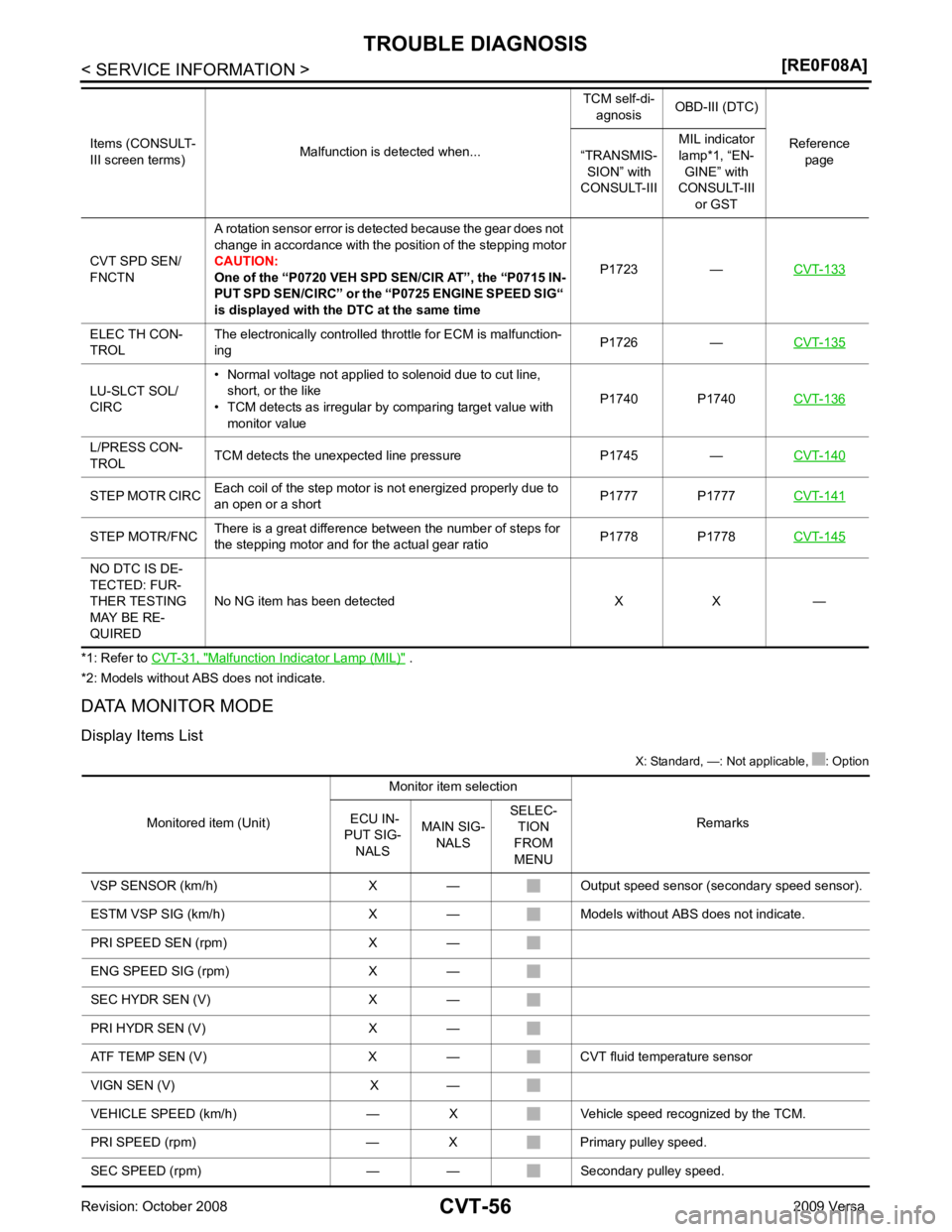
Malfunction Indicator Lamp (MIL) " .
*2: Models without ABS does not indicate.
DATA MONITOR MODE
Display Items List X: Standard, —: Not applicable, : Option
CVT SPD SEN/
FNCTN A rotation sensor error is detected because the gear does not
change in accordance with the position of the stepping motor
CAUTION:
One of the “P0720 VEH SPD SEN/CIR AT”, the “P0715 IN-
PUT SPD SEN/CIRC” or the “P0725 ENGINE SPEED SIG“
is displayed with the DTC at the same time P1723 —
CVT-133ELEC TH CON-
TROL The electronically controlled throttle for ECM is malfunction-
ing P1726 —
CVT-135LU-SLCT SOL/
CIRC • Normal voltage not applied to solenoid due to cut line,
short, or the like
• TCM detects as irregular by comparing target value with
monitor value P1740 P1740
CVT-136L/PRESS CON-
TROL TCM detects the unexpected line pressure P1745 —
CVT-140STEP MOTR CIRC
Each coil of the step motor is not energized properly due to
an open or a short P1777 P1777
CVT-141STEP MOTR/FNC
There is a great difference between the number of steps for
the stepping motor and for the actual gear ratio P1778 P1778
CVT-145NO DTC IS DE-
TECTED: FUR-
THER TESTING
MAY BE RE-
QUIRED No NG item has been detected X X —
Items (CONSULT-
III screen terms) Malfunction is detected when... TCM self-di-
agnosis OBD-III (DTC)
Reference page
“TRANSMIS-
SION” with
CONSULT-III MIL indicator
lamp*1, “EN- GINE” with
CONSULT-III
or GST
Page 1001 of 4331
CVT
N
O P
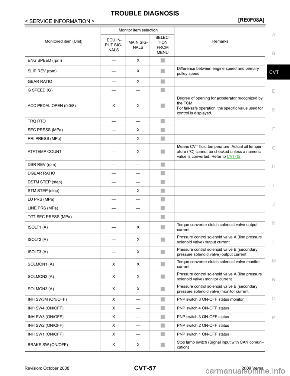
ENG SPEED (rpm) — X
SLIP REV (rpm) — X Difference between engine speed and primary
pulley speed
GEAR RATIO — X
G SPEED (G) — —
ACC PEDAL OPEN (0.0/8) X X Degree of opening for accelerator recognized by
the TCM
For fail-safe operation, the specific value used for
control is displayed.
TRQ RTO — —
SEC PRESS (MPa) — X
PRI PRESS (MPa) — X
ATFTEMP COUNT — X Means CVT fluid temperature. Actual oil temper-
ature ( °C) cannot be checked unless a numeric
value is converted. Refer to CVT-12 .
DSR REV (rpm) — —
DGEAR RATIO — —
DSTM STEP (step) — —
STM STEP (step) — X
LU PRS (MPa) — —
LINE PRS (MPa) — —
TGT SEC PRESS (MPa) — —
ISOLT1 (A) — X Torque converter clutch solenoid valve output
current
ISOLT2 (A) — X Pressure control solenoid valve A (line pressure
solenoid valve) output current
ISOLT3 (A) — X Pressure control solenoid valve B (secondary
pressure solenoid valve) output current
SOLMON1 (A) X X Torque converter clutch solenoid valve monitor
current
SOLMON2 (A) X X Pressure control solenoid valve A (line pressure
solenoid valve) monitor current
SOLMON3 (A) X X Pressure control solenoid valve B (secondary
pressure solenoid va lve) monitor current
INH SW3M (ON/OFF) X — PNP switch 3 ON-OFF status monitor
INH SW4 (ON/OFF) X — PNP switch 4 ON-OFF status
INH SW3 (ON/OFF) X — PNP switch 3 ON-OFF status
INH SW2 (ON/OFF) X — PNP switch 2 ON-OFF status
INH SW1 (ON/OFF) X — PNP switch 1 ON-OFF status
BRAKE SW (ON/OFF) X X Stop lamp switch (Signal input with CAN comuni-
cation)
Monitored item (Unit)
Monitor item selection
Remarks
ECU IN-
PUT SIG- NALS MAIN SIG-
NALS SELEC-
TION
FROM
MENU
Page 1007 of 4331
CVT
N
O P
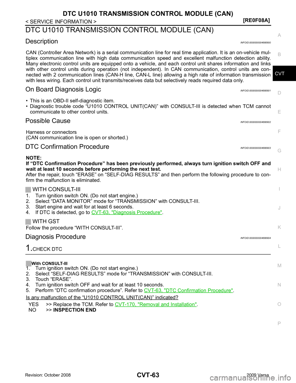
DTC U1010 TRANSMISSION
CONTROL MODULE (CAN)
Description INFOID:0000000004666900
CAN (Controller Area Network) is a serial communication li ne for real time application. It is an on-vehicle mul-
tiplex communication line with high data communica tion speed and excellent malfunction detection ability.
Many electronic control units are equipped onto a vehicl e, and each control unit shares information and links
with other control units during operation (not independent ). In CAN communication, control units are con-
nected with 2 communication lines (CAN-H line, CAN-L li ne) allowing a high rate of information transmission
with less wiring. Each control unit transmits/recei ves data but selectively reads required data only.
On Board Diagnosis Logic INFOID:0000000004666901
• This is an OBD-II self-diagnostic item.
• Diagnostic trouble code “U1010 CONTROL UNIT(CAN)” with CONSULT-III is detected when TCM cannot
communicate to other control units.
Possible Cause INFOID:0000000004666902
Harness or connectors
(CAN communication line is open or shorted.)
DTC Confirmation Procedure INFOID:0000000004666903
NOTE:
If “DTC Confirmation Procedure” has been previously performed, alw ays turn ignition switch OFF and
wait at least 10 seconds before performing the next test.
After the repair, touch “ERASE” on “SELF-DIAG RESU LTS” and then perform the following procedure to con-
firm the malfunction is eliminated.
WITH CONSULT-III
1. Turn ignition switch ON. (Do not start engine.)
2. Select “DATA MONITOR” mode for “TRANSMISSION” with CONSULT-III.
3. Start engine and wait for at least 6 seconds.
4. If DTC is detected, go to CVT-63, " Diagnosis Procedure " .
WITH GST
Follow the procedure “WITH CONSULT-III”.
Diagnosis Procedure INFOID:0000000004666904DTC Confirmation Procedure " .
Is any malfunction of the “ U1010 CONTROL UNIT(CAN) ” indicated?
YES >> Replace the TCM. Refer to
CVT-170, " Removal and Installation " .
NO >> INSPECTION END
Page 1013 of 4331

CVT
N
O P
DTC P0705 PARK/NEUTRAL POSITION SWITCH
Description INFOID:0000000004666918
• The PNP switch is included in the control valve assembly.
• The PNP switch includes 4 transmission position switches.
• TCM judges the selector lever position by the PNP switch signal.
CONSULT-III Reference Val ue in Data Monitor Mode INFOID:0000000004666919
On Board Diagnosis Logic INFOID:0000000004666920
• This is an OBD-II self-diagnostic item.
• Diagnostic trouble code “P0705 PNP SW/CIRC” with CO NSULT-III is detected under the following condi-
tions.
- When TCM does not receive the correct voltage signal from the PNP switches 1, 2, 3 and 4 based on the gear position.
- When the signal from monitor terminal of PNP switch 3 is different from PNP switch 3.
Possible Cause INFOID:0000000004666921
• Harness or connectors (PNP switches 1, 2, 3, 4 and TCM circuit is open or shorted.)
• PNP switches 1, 2, 3, 4
• PNP switch 3 monitor terminal is open or shorted
DTC Confirmation Procedure INFOID:0000000004666922
CAUTION:
Always drive vehicle at a safe speed.
NOTE:
If “DTC Confirmation Procedure” has been previously performed, alw ays turn ignition switch OFF and
wait at least 10 seconds before performing the next test.
After the repair, touch “ERASE” on “SELF-DIAG RESU LTS” and then perform the following procedure to con-
firm the malfunction is eliminated.
WITH CONSULT-III
Shift position PNP switch 1 PNP switch 2 PNP switch 3 PNP switch 4 PNP switch 3 (monitor)
P OFF OFF OFF OFF OFF
R ON OFF OFF ON OFF
N ON ON OFF OFF OFF
D ON ON ON ON ON L OFF ON ON OFF ON Item name Condition Display value
INH SW3M Selector lever in “D
” and “L” positions ON
Selector lever in “P”, “R” and “N” positions OFF
INH SW4 Selector lever in “R
” and “D” positions ON
Selector lever in “P”, “N” and “L” positions OFF
INH SW3 Selector lever in “D
” and “L” positions ON
Selector lever in “P”, “R” and “N” positions OFF
INH SW2 Selector lever in “N”,
“D” and “L” positions ON
Selector lever in “P ” and “R” positions OFF
INH SW1 Selector lever in “R”,
“N” and “D” positions ON
Selector lever in “P” and “L” positions OFF
Page 1018 of 4331
OK >>
INSPECTION END
NG >> GO TO 6. TCM Terminal and Reference Value " .
2. If NG, re-check TCM pin terminals for damage or loose connection with harness connector.
OK or NG OK >>
INSPECTION END
NG >> 1. Repair or replace damaged parts.
2. Replace the transaxle assembly. Refer to CVT-182, " Removal and Installation " .
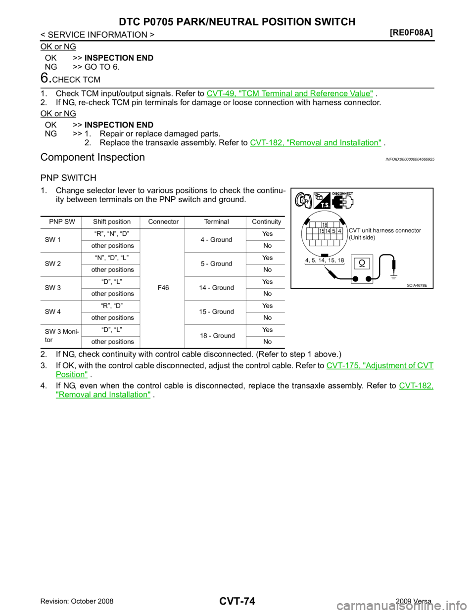
Component Inspection INFOID:0000000004666925
PNP SWITCH
1. Change selector lever to various positions to check the continu- ity between terminals on the PNP switch and ground.
2. If NG, check continuity with control c able disconnected. (Refer to step 1 above.)
3. If OK, with the control cable disconnect ed, adjust the control cable. Refer to CVT-175, " Adjustment of CVT
Position " .
4. If NG, even when the control cable is disconnected, replace the transaxle assembly. Refer to CVT-182," Removal and Installation " .
PNP SW Shift position Connector Terminal Continuity
SW 1 “R”, “N”, “D”
F464 - Ground
Yes
other positions No
SW 2 “N”, “D”, “L”
5 - Ground Yes
other positions No
SW 3 “D”, “L”
14 - Ground Yes
other positions No
SW 4 “R”, “D”
15 - Ground Yes
other positions No
SW 3 Moni-
tor “D”, “L”
18 - Ground Yes
other positions No
Page 1019 of 4331
CVT
N
O P
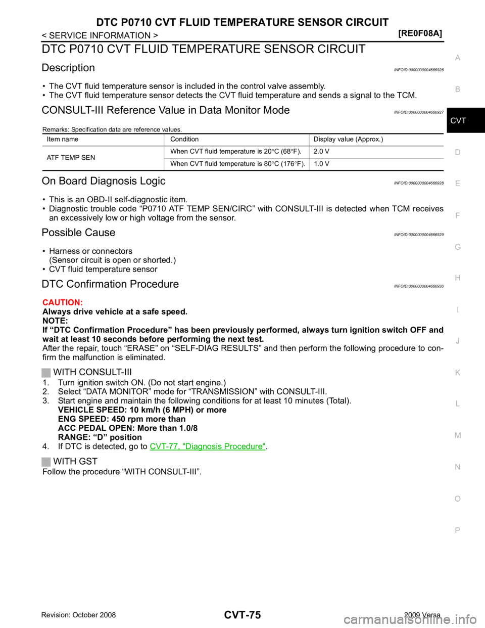
DTC P0710 CVT FLUID TEMPER
ATURE SENSOR CIRCUIT
Description INFOID:0000000004666926
• The CVT fluid temperature sensor is included in the control valve assembly.
• The CVT fluid temperature sensor detects the CV T fluid temperature and sends a signal to the TCM.
CONSULT-III Reference Val ue in Data Monitor Mode INFOID:0000000004666927
Remarks: Specification data are reference values.
On Board Diagnosis Logic INFOID:0000000004666928
• This is an OBD-II self-diagnostic item.
• Diagnostic trouble code “P0710 ATF TEMP SEN/CIRC” with CONSULT-III is detected when TCM receives
an excessively low or high voltage from the sensor.
Possible Cause INFOID:0000000004666929
• Harness or connectors (Sensor circuit is open or shorted.)
• CVT fluid temperature sensor
DTC Confirmation Procedure INFOID:0000000004666930
CAUTION:
Always drive vehicle at a safe speed.
NOTE:
If “DTC Confirmation Procedure” has been previously performed, alw ays turn ignition switch OFF and
wait at least 10 seconds before performing the next test.
After the repair, touch “ERASE” on “SELF-DIAG RESU LTS” and then perform the following procedure to con-
firm the malfunction is eliminated.
WITH CONSULT-III
1. Turn ignition switch ON. (Do not start engine.)
2. Select “DATA MONITOR” mode for “TRANSMISSION” with CONSULT-III.
3. Start engine and maintain the following conditions for at least 10 minutes (Total). VEHICLE SPEED: 10 km/h (6 MPH) or more
ENG SPEED: 450 rpm more than
ACC PEDAL OPEN: More than 1.0/8
RANGE: “D” position
4. If DTC is detected, go to CVT-77, " Diagnosis Procedure " .
WITH GST
Follow the procedure “WITH CONSULT-III”. Item name Condition Display value (Approx.)
ATF TEMP SEN When CVT fluid temperature is 20
°C (68 °F). 2.0 V
When CVT fluid temperature is 80 °C (176 °F). 1.0 V
Page 1041 of 4331
CVT
N
O P
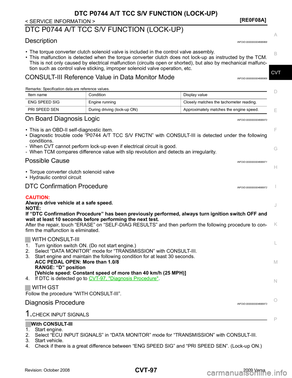
DTC P0744 A/T TCC S/V FUNCTION (LOCK-UP)
Description INFOID:0000000004666968
• The torque converter clutch solenoid valve is included in the control valve assembly.
• This malfunction is detected when the torque converter clutch does not lock-up as instructed by the TCM.
This is not only caused by electrical malfunction (cir cuits open or shorted), but also by mechanical malfunc-
tion such as control valve sticking, improper solenoid valve operation, etc.
CONSULT-III Reference Val ue in Data Monitor Mode INFOID:0000000004666969
Remarks: Specification data are reference values.
On Board Diagnosis Logic INFOID:0000000004666970
• This is an OBD-II self-diagnostic item.
• Diagnostic trouble code “P0744 A/T TCC S/V FNCTN” wit h CONSULT-III is detected under the following
conditions.
- When CVT cannot perform lock-up even if electrical circuit is good.
- When TCM compares difference value with slip revolution and detects an irregularity.
Possible Cause INFOID:0000000004666971
• Torque converter clutch solenoid valve
• Hydraulic control circuit
DTC Confirmation Procedure INFOID:0000000004666972
CAUTION:
Always drive vehicle at a safe speed.
NOTE:
If “DTC Confirmation Procedure” has been previously performed, alw ays turn ignition switch OFF and
wait at least 10 seconds before performing the next test.
After the repair, touch “ERASE” on “SELF-DIAG RESU LTS” and then perform the following procedure to con-
firm the malfunction is eliminated.
WITH CONSULT-III
1. Turn ignition switch ON. (Do not start engine.)
2. Select “DATA MONITOR” mode for “TRANSMISSION” with CONSULT-III.
3. Start engine and maintain the following condition for at least 30 seconds.
ACC PEDAL OPEN: More than 1.0/8
RANGE: “D” position
[Vehicle speed: Constant speed of more than 40 km/h (25 MPH)]
4. If DTC is detected go to CVT-97, " Diagnosis Procedure " .
WITH GST
Follow the procedure “WITH CONSULT-III”.
Diagnosis Procedure INFOID:0000000004666973
Page 1043 of 4331
CVT
N
O P
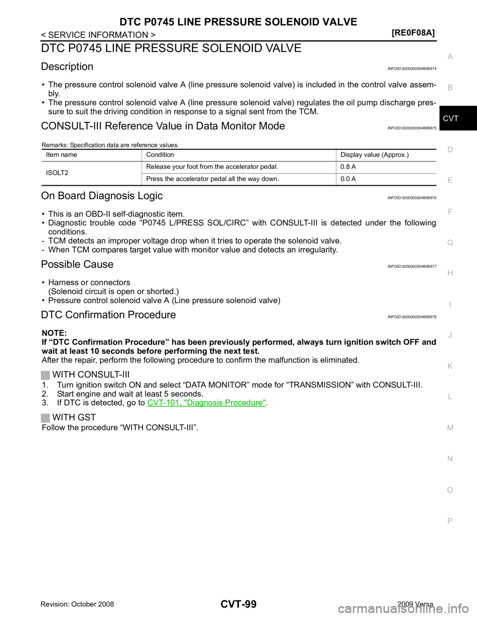
DTC P0745 LINE PRESSURE SOLENOID VALVE
Description INFOID:0000000004666974
• The pressure control solenoid valve A (line pressure solenoid valve) is included in the control valve assem- bly.
• The pressure control solenoid valve A (line pressure solenoid valve) regulates the oil pump discharge pres-
sure to suit the driving condition in response to a signal sent from the TCM.
CONSULT-III Reference Val ue in Data Monitor Mode INFOID:0000000004666975
Remarks: Specification data are reference values.
On Board Diagnosis Logic INFOID:0000000004666976
• This is an OBD-II self-diagnostic item.
• Diagnostic trouble code “P0745 L/PRESS SOL/CIRC” with CONSULT-III is detected under the following
conditions.
- TCM detects an improper voltage drop when it tries to operate the solenoid valve.
- When TCM compares target value with monitor value and detects an irregularity.
Possible Cause INFOID:0000000004666977
• Harness or connectors (Solenoid circuit is open or shorted.)
• Pressure control solenoid valve A (Line pressure solenoid valve)
DTC Confirmation Procedure INFOID:0000000004666978
NOTE:
If “DTC Confirmation Procedure” has been previously performed, alw ays turn ignition switch OFF and
wait at least 10 seconds before performing the next test.
After the repair, perform the following procedure to confirm the malfunction is eliminated.
WITH CONSULT-III
1. Turn ignition switch ON and select “DATA MO NITOR” mode for “TRANSMISSION” with CONSULT-III.
2. Start engine and wait at least 5 seconds.
3. If DTC is detected, go to CVT-101, " Diagnosis Procedure " .
WITH GST
Follow the procedure “WITH CONSULT-III”. Item name Condition Display value (Approx.)
ISOLT2 Release your foot from the accelerator pedal. 0.8 A
Press the accelerator pedal all the way down. 0.0 A